Page 100 of 4087
Actuator check.
(1) Warm up the engine.
(2) Set to the actuator check mode (See pageAC-30 ).
(3) Press the FRS switch and change it to step operation.
Press the FRS switch and check the
operation of the air mix damper and the condition
of the blower.
Proceed to next circuit inspection shown on
matrix chart (See page AC-36).
Check air mix servomotor.
Remove heater unit.
Connect positive � lead to terminal 4 and negative
� lead to terminal 5.
The lever turns smoothly to cool side.
Connect negative � lead to terminal 4 and positive �
lead to terminal 5.
The lever turns smoothly to hot side.
Replace air mix servomotor assembly.
Check for open and short in harness and connector between air conditioner
control assembly and air mix servomotor assembly (See page IN-27).
Repair or replace harness or connector.
Check and replace air conditioner control
assembly.
INSPECTION PROCEDURE
±
AIR CONDITIONING SYSTEM TroubleshootingAC±61
WhereEverybodyKnowsYourName
Page 121 of 4087
������������������\
������������������\
�
������������������\
�����������������
������������������\
������������������\
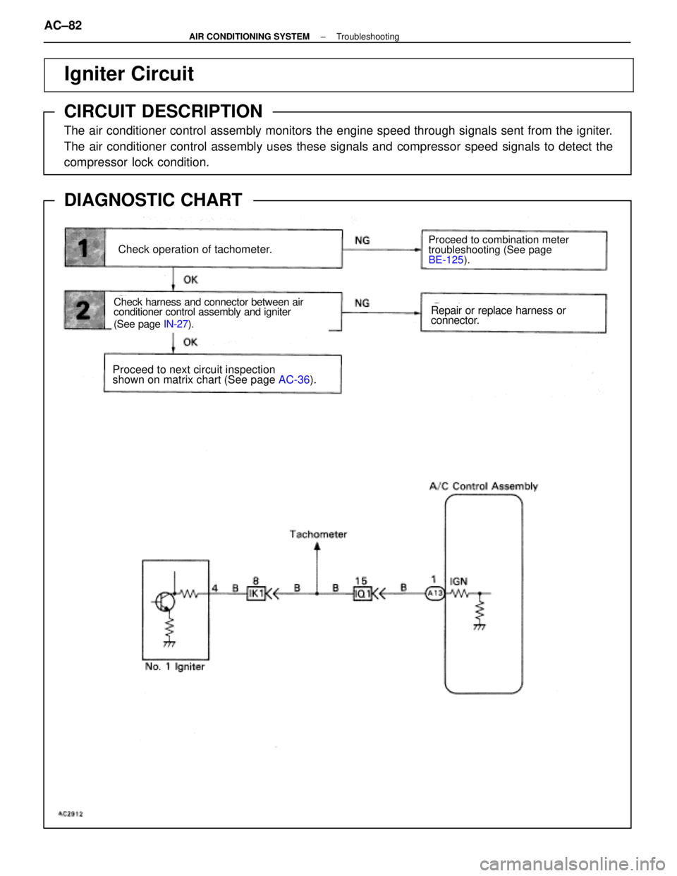
Igniter Circuit
CIRCUIT DESCRIPTION
The air conditioner control assembly monitors the engine speed through sign\
als sent from the igniter.
The air conditioner control assembly uses these signals and compressor speed signals to detect the
compressor lock condition.
DIAGNOSTIC CHART
WIRING DIAGRAM
Check operation of tachometer.
Check harness and connector between air
conditioner control assembly and igniter
(See page IN-27).
Proceed to combination meter
troubleshooting (See page
BE-125 ).
Proceed to next circuit inspection
shown on matrix chart (See page AC-36).
Repair or replace harness or
connector.
AC±82±
AIR CONDITIONING SYSTEM Troubleshooting
WhereEverybodyKnowsYourName
Page 124 of 4087

Check voltage between terminals A/C IN of air
conditioner control assembly connector and
body ground .
Check A/C compressor magnetic clutch.
Check harness and connector between
A/C compressor and compressor relay
(See page IN-27).
Proceed to next circuit inspection
shown on matrix chart (See page AC-36).
Check voltage between terminals MGC of air
conditioner control assembly connector and
body ground .
Check voltage between terminals MGC of air
conditioner control assembly harness side con-
nector and body ground .
Check harness and connector between
air conditioner control assembly and
engine & ECT ECU (See page iN±27).
Check and replace engine & ECT ECU.
Check magnetic clutch relay.
Repair A/C compressor magnetic
clutch.
Repair or replace harness or
connector.
Check and replace air conditioner
control assembly.
Repair or replace harness or
connector.
Replace magnetic clutch relay.
Check voltage between terminals ACMG of
engine & ECT ECU and body ground .
Check harness and connector between
engine & ECT ECU and battery (See page
IN-27).
Check and replace engine & ECT ECU.
Repair or replace harness or
connector.
Check harness and connector between
air conditioner control assembly and
compressor relay, compressor relay and
battery (See page IN±27 ).
Repair or replace harness or
connector.
Check and replace air conditioner control
assembly.
±
AIR CONDITIONING SYSTEM TroubleshootingAC±85
WhereEverybodyKnowsYourName
Page 125 of 4087
 Remove console upper panel.(See pageBO-111 ).
(2) Remove A/C control assembly with
connecto")
Check voltage between terminals A/C IN of air conditioner control
assembly connector and body ground.
(1) Remove console upper panel.(See pageBO-111 ).
(2) Remove A/C control assembly with
connectors still connected.
(3) Start the engine.
Check voltage between terminals A/C IN of air condi-
tioner control assembly and body ground when mag-
netic clutch is on and off by A/C switch
Go to step (4).
Check air conditioner compressor magnetic clutch.
Disconnect magnetic clutch connector.
Connect positive � lead connected to battery to mag-
netic clutch connector terminal 3.
Magnetic clutch is energized.
Repair air conditioner compr essor magnetic
clutch.
Check for open and short in harness and connecter between air
conditioner compressor and compressor relay (See page IN-27).
Repair or replace harness or connector.
Proceed to next circuit inspection shown on ma-
trix chart (See page AC-36).
INSPECTION PROCEDURE
AC±86±
AIR CONDITIONING SYSTEM Troubleshooting
WhereEverybodyKnowsYourName
Page 126 of 4087
 Remove console upper panel.(See page BO-111 ).
(2) Remove A/C control assembly with connec±")
Check voltage between terminals MGC of air conditioner control assem-
bly connector and body ground.
(1) Remove console upper panel.(See page BO-111 ).
(2) Remove A/C control assembly with connec±
tors still connected.
(3) Start the engine.
Check voltage between terminals MGC of air condi-
tioner control assembly connector and body ground
when magnetic clutch is on and off by A/C
switch.
Go to step (7).
Check voltage between terminals MGC of air conditioner control assem-
bly harness side connector and body ground.
(1) Disconnect air conditioner control assemblyconnector.
(3) Turn ignition switch ON.
Check voltage between terminals MGC of air condi-
tioner control assembly harness side connector and
body ground.
Voltage: 4 ± 6 V
Check and replace air conditioner control
assembly.
Check for open and short in harness and connector between
air conditioner control assembly and engine & ECT ECU (See page IN-27).
Repair or replace harness or connector.
Check and replace engine & ECT ECU.
±
AIR CONDITIONING SYSTEM TroubleshootingAC±87
WhereEverybodyKnowsYourName
Page 127 of 4087
 Apply battery voltage between termin")
Check magnetic clutch relay.
Remove magnetic clutch relay from R/B No. 2
Check continuity between each pair of terminals
shown below of magnetic clutch relay.
(1) Apply battery voltage between terminals 2 and 3
(2) Check continuity between terminals 4 and 1
Replace magnetic relay.
(1) Remove engine & ECT ECU with connectors still connected.
(2) Turn ignition switch ON.
(1) Push one of the fan speed control switches
(Lo, Med or Hi).
(2) Measure voltage between terminal ACMG of engine & ECT ECU connector and body
ground.
Go to step (10).
Check voltage between terminal ACMG of engine & ECT ECU and
body ground.
Check for open and short in harness and connector between engine &
ECT ECU and battery (See page IN-27).
Repair or replace harness or connector.
Check and replace engine & ECT ECU.
Check for open and short in harness and connector between air conditioner control
assembly and compressor relay, compressor relay and battery (See page IN-27).
Repair or replace harness or connector.
Check and replace air conditioner control a ssembly.
AC±88±
AIR CONDITIONING SYSTEM Troubleshooting
WhereEverybodyKnowsYourName
Page 128 of 4087

������������������\
������������������\
�
������������������\
�����������������
������������������\
������������������\
Water Valve VSV Circuit
CIRCUIT DESCRIPTION
If the target air mix damper position is on the hot side beyond a predeter\
mined level, the A/C control
assembly turns ON Tr inside the A/C control assembly.
This turns the water valve VSV ON so that engine coolant flows to the he\
ater core.
If the target air mix damper position is on the cool side beyond a prede\
termined level, the A/C control
assembly OFF Tr inside the A/C control assembly.
This turns OFF the VSV and stops circulation of engine coolant to the he\
ater core, thus increasing the
cooling performance.
DIAGNOSTIC CHART
Check voltage between terminal WV of A/C
control assembly connector and body
ground .
Check water valve VSV.
Check for open and short in harness
and connector between VSV and A/C
control assembly .
Check and replace A/C control assembly.
Replace water valve VSV.
Repair or replace harness or
connector.
Proceed to next circuit inspection
shown on matrix chart
(See page
AC-36).
WIRING DIAGRAM
AC±90±
AIR CONDITIONING SYSTEM Troubleshooting
WhereEverybodyKnowsYourName
Page 129 of 4087
 Remove console upper panel.(See page
BO-111).
(2) Remove A/C control assembly with connec±
tors still connec")
Check voltage between terminal WV of A/C control assembly connec-
tor body ground.
(1) Remove console upper panel.(See page
BO-111).
(2) Remove A/C control assembly with connec±
tors still connected.
(3) Start the engine.
Measure voltage between terminals WV of A/C con-
trol assembly connector and body ground
when the set temp. is not set to MAX COLD and
MAX HOT.
Proceed to next circuit inspection shown on
matrix chart. ( See page AC-36).
Check water valve VSV.
Water valve VSV connector.
Measure resistance between terminals of VSV con-
nector.
Resistance: 37 ± 47 � at 20°C (68°F)
Check operation of water valve VSV when battery
voltage is applied to terminals of VSV connector or
not.
� Battery voltage is applied:
The air from A is flowing out through B.
� Battery voltage is not applied:
The air from A is flowing out through air filter.
Replace water valve VSV.
Check for open and short in harness and connector between VSV
and A/C control assembly (See page IN-27).
Repair or replace harness or connector.
Check and replace A/C control assembly.
INSPECTION PROCEDURE
±
AIR CONDITIONING SYSTEM TroubleshootingAC±91
WhereEverybodyKnowsYourName
 Warm up the engine.
(2) Set to the actuator check mode (See pageAC-30 ).
(3) Press the FRS switch and change it to step operation.
Press the FRS switch a")