Page 2609 of 4087
24. CONNECT CONTROL CABLES TO THROTTLE BODYConnect the following hoses:(1) Accelerator cable
(2) A/T throttle control cable
(3) (w/ Cruise Control System) Cruise control actuator cable
25. INSTALL THROTTLE BODY COVER Install the throttle body cover and hose clamp with the two
bolts and cap nut.
26. C O N N E C T C A B L E TO N E G AT I V E T E R M I N A L O F BATTERY
27. FILL WITH ENGINE COOLANT (See page CO±7)
28. CHECK THAT ENGINE STARTS
ST±34
±
STARTING SYSTEM Starter
WhereEverybodyKnowsYourName
Page 2673 of 4087

Diag. Code 21, 28Main Oxygen Sensor Circuit
CIRCUIT DESCRIPTION
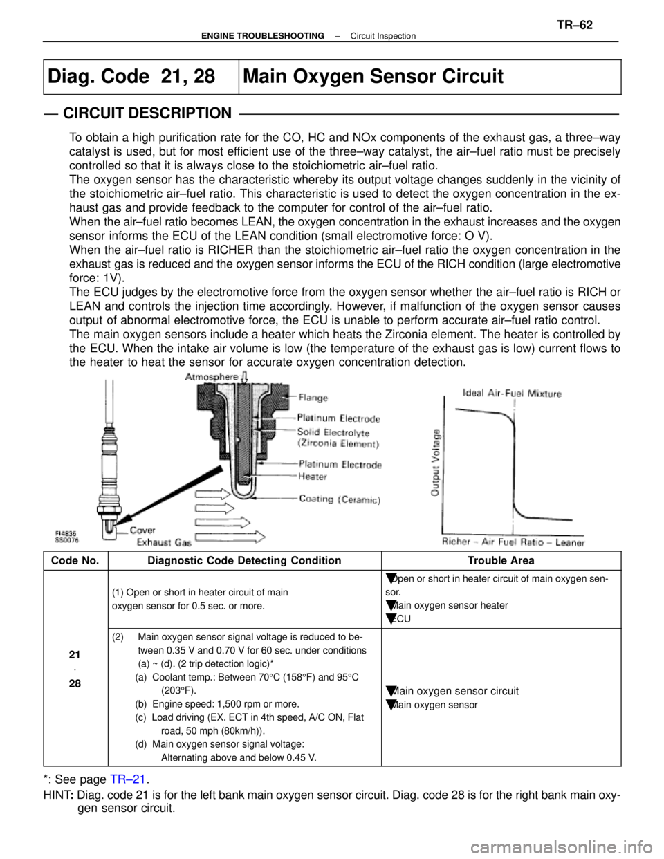
To obtain a high purification rate for the CO, HC and NOx components of th\
e exhaust gas, a three±way
catalyst is used, but for most efficient use of the three±way catalyst, the air±fuel ratio must be \
precisely
controlled so that it is always close to the stoichiometric air±fuel \
ratio.
The oxygen sensor has the characteristic whereby its output voltage chan\
ges suddenly in the vicinity of
the stoichiometric air±fuel ratio. This characteristic is used to det\
ect the oxygen concentration in the ex-
haust gas and provide feedback to the computer for control of the air±\
fuel ratio.
When the air±fuel ratio becomes LEAN, the oxygen concentration in the exh\
aust increases and the oxygen
sensor informs the ECU of the LEAN condition (small electromotive force: O V)\
.
When the air±fuel ratio is RICHER than the stoichiometric air±fuel\
ratio the oxygen concentration in the
exhaust gas is reduced and the oxygen sensor informs the ECU of the RICH condition (large electromotive
force: 1V).
The ECU judges by the electromotive force from the oxygen sensor whether th\
e air±fuel ratio is RICH or
LEAN and controls the injection time accordingly. However, if malfunction of the oxygen sensor causes
output of abnormal electromotive force, the ECU is unable to perform accurate \
air±fuel ratio control.
The main oxygen sensors include a heater which heats the Zirconia element. The heater is controlled by
the ECU. When the intake air volume is low (the temperature of the exhaust\
gas is low) current flows to
the heater to heat the sensor for accurate oxygen concentration detectio\
n.
Code No.Diagnostic Code Detecting ConditionTrouble Area
(1) Open or short in heater circuit of main
oxygen sensor for 0.5 sec. or more.
�Open or short in heater circuit of main oxygen sen-
sor.
�Main oxygen sensor heater
�ECU
21 V
28
(2) Main oxygen sensor signal voltage is reduced to be-
tween 0.35 V and 0.70 V for 60 sec. under conditions
(a) ~ (d). (2 trip detection logic)*
(a) Coolant temp.: Between 70 5C (158 5F) and 95 5C
(203 5F).
(b) Engine speed: 1,500 rpm or more.
(c) Load driving (EX. ECT in 4th speed, A/C ON, Flat road, 50 mph (80km/h)).
(d) Main oxygen sensor signal voltage:
Alternating above and below 0.45 V.
�Main oxygen sensor circuit
�Main oxygen sensor
*: See page TR±21.
HINT : Diag. code 21 is for the left bank main oxygen sensor circuit. Diag. co\
de 28 is for the right bank main oxy-
gen sensor circuit.
±
ENGINE TROUBLESHOOTING Circuit InspectionTR±62
WhereEverybodyKnowsYourName
Page 2679 of 4087

Diag. Code 22Water Temp. Sensor Circuit
CIRCUIT DESCRIPTION
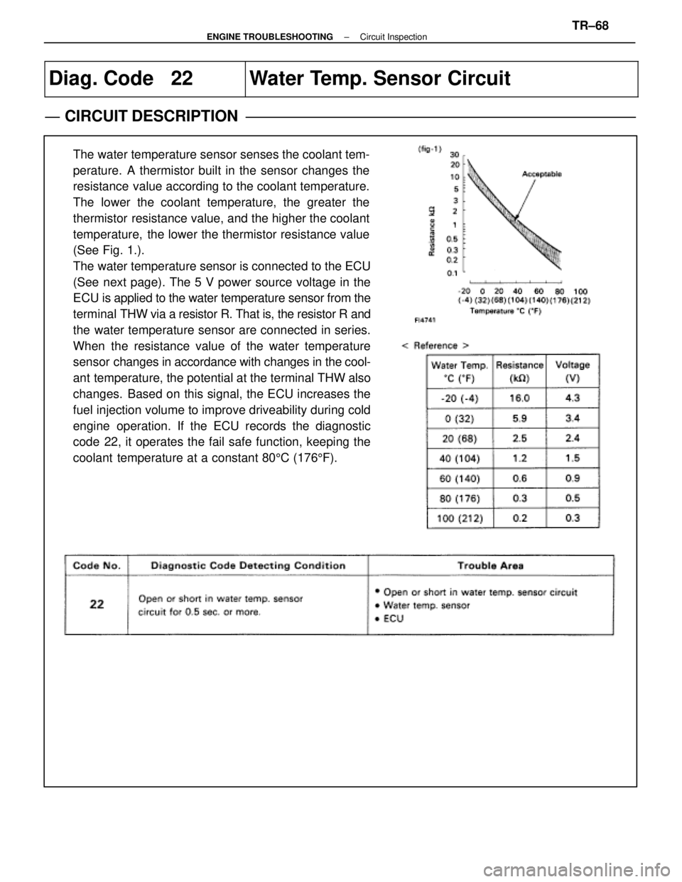
The water temperature sensor senses the coolant tem-
perature. A thermistor built in the sensor changes the
resistance value according to the coolant temperature.
The lower the coolant temperature, the greater the
thermistor resistance value, and the higher the coolant
temperature, the lower the thermistor resistance value
(See Fig. 1.).
The water temperature sensor is connected to the ECU
(See next page). The 5 V power source voltage in the
ECU is applied to the water temperature sensor from the
terminal THW via a resistor R. That is, the resistor R and
the water temperature sensor are connected in series.
When the resistance value of the water temperature
sensor changes in accordance with changes in the cool-
ant temperature, the potential at the terminal THW also
changes. Based on this signal, the ECU increases the
fuel injection volume to improve driveability during cold
engine operation. If the ECU records the diagnostic
code 22, it operates the fail safe function, keeping the
coolant temperature at a constant 80 5C (176 5F).
±
ENGINE TROUBLESHOOTING Circuit InspectionTR±68
WhereEverybodyKnowsYourName
Page 2685 of 4087

Diag Code
25Air±Fuel Ratio Lean Malfunction
Diag. Code
26Air±Fuel Ratio Rich Malfunction
CIRCUIT DESCRIPTION
Refer to page TR±62 for the circuit description.
Code No.Diagnostic Code Detecting ConditionTrouble Area
(1) Main oxygen sensor voltage is 0.45 V or less (lean)
for 90 sec. under conditions (a) and (b).
(2 trip detection logic)*
(a) Coolant temp.: 60 5C (140 5F) or more.
(b) Engine speed: 1,500 rpm or more.�Open or short in main oxygen sensor circuit
�Main oxygen sensor
�Ignition system
�Water temp. sensor
25 V
26
(2) Main oxygen sensor voltage is alternating above and below 0.45 V at 5 times par
second or more under conditions (a) and (b).
(2 trip detection logic)*
(a) Engine speed: Idling
(b) Coolant temp.: Between 60 5C (140 5F)
and 95 5C (203 5F)
�Open or short in injector circuit.
�Fuel line pressure (injector blockage)
�Air flow meter (air intake)
�Engine ground bolt loose
�Foreign object caught in valve
(3) Difference of air±fuel ratio feedback compensation
value between right and left banks is more than 10
percentage for 30 sec. or more under conditions (a)
and (b).
(2 trip detection logic)*
(a) Engine speed : 2,000 rpm or more.
(b) Coolant temp.: Between 60 5C (140 5F)
and 95 5C (203 5F)
�Fuel line pressure (injector leak, blockage)
�Mechanical system malfunction
(skipping teeth of timing belt)
�Ignition system
*: See page TR±21.
±
ENGINE TROUBLESHOOTING Circuit InspectionTR±74
WhereEverybodyKnowsYourName
Page 2693 of 4087
Diag. Code 27, 29Sub±Oxygen Sensor Circuit
CIRCUIT DESCRIPTION
The sub±oxygen sensor is installed on the exhaust pipe. Its construction\
and operation is the same as the main
oxygen sensor on page TR±62.
Code No.Diagnostic Code Detecting ConditionTrouble Area
(1) Open or short in heater circuit of sub±oxygen
sensor for 0.5 sec. or more.
�Open or short in heater circuit of sub±oxygen
sensor
� Sub±oxygen sensor heater.
� ECU
27
�
29(2) Main oxygen sensor signal is 0.45 V or more and sub±oxygen sensor signal is 0.45 V or less
under sonditions (a) and (b).
(2 trip detection logic) *
(a) Coolant temp.: 80 5C (176 5F) or more.
(b) Accel. pedal: Fully depressed for 2 sec. or more.
�Open or short in sub±oxygen sensor circuit.
� Sub±oxygen sensor
� ECU
*: See page TR±21.
HINT: Diag. code 27 is for the left bank sub±oxygen sensor circuit.
Diag. code 29 is for the right bank sub±oxygen sensor circuit.
TR±82
±
ENGINE TROUBLESHOOTING Circuit Inspection
WhereEverybodyKnowsYourName
Page 2719 of 4087

Diag. Code 71
EGR System Malfunction (Only for USA
spec.)
CIRCUIT DESCRIPTION
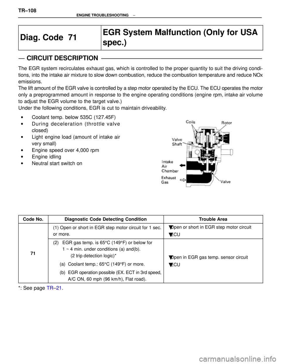
The EGR system recirculates exhaust gas, which is controlled to the proper quantity to suit the driv\
ing condi-
tions, into the intake air mixture to slow down combustion, reduce the combust\
ion temperature and reduce NOx
emissions.
The lift amount of the EGR valve is controlled by a step motor operated \
by the ECU. The ECU operates the motor
only a preprogrammed amount in response to the engine operating conditions (\
engine rpm, intake air volume
to adjust the EGR volume to the target valve.)
Under the following conditions, EGR is cut to maintain driveability.
wCoolant temp. below 535C (127.45F)
w During deceleration (throttle valve
closed)
w Light engine load (amount of intake air
very small)
w Engine speed over 4,000 rpm
w Engine idling
w Neutral start switch on
Code No.Diagnostic Code Detecting ConditionTrouble Area
(1) Open or short in EGR step motor circuit for 1 sec.
or more.�Open or short in EGR step motor circuit
� ECU
71
(2) EGR gas temp. is 65 5C (149 5F) or below for
1 ~ 4 min. under conditions (a) and(b).
(2 trip detection logic)*
(a) Coolant temp.: 65 5C (149 5F) or more.
(b) EGR operation possible (EX. ECT in 3rd speed, A/C ON, 60 mph (96 km/h), Flat road).
�Open in EGR gas temp. sensor circuit
� ECU
*: See page TR±21.
TR±108
±
ENGINE TROUBLESHOOTING
WhereEverybodyKnowsYourName
Page 2747 of 4087

Cold Start Injector Circuit
CIRCUIT DESCRIPTION
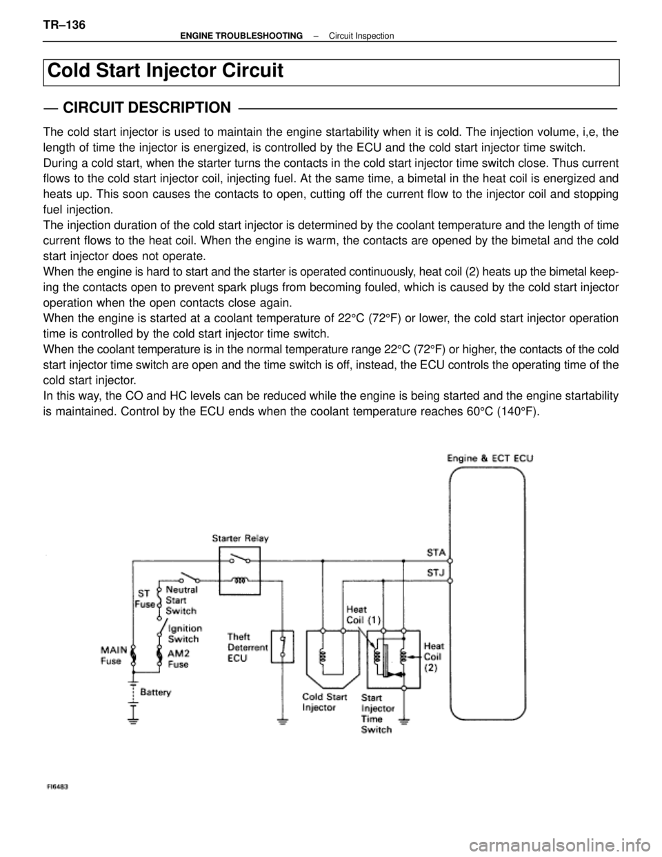
The cold start injector is used to maintain the engine startability when it\
is cold. The injection volume, i,e, the
length of time the injector is energized, is controlled by the ECU and t\
he cold start injector time switch.
During a cold start, when the starter turns the contacts in the cold start inj\
ector time switch close. Thus current
flows to the cold start injector coil, injecting fuel. At the same time, a bi\
metal in the heat coil is energized and
heats up. This soon causes the contacts to open, cutting off the current flow to the injector coil and stopping
fuel injection.
The injection duration of the cold start injector is determined by the cool\
ant temperature and the length of time
current flows to the heat coil. When the engine is warm, the contacts are opened by the bimetal and the cold
start injector does not operate.
When the engine is hard to start and the starter is operated continuously, heat coil (2) heats up the bimetal keep-
ing the contacts open to prevent spark plugs from becoming fouled, which is\
caused by the cold start injector
operation when the open contacts close again.
When the engine is started at a coolant temperature of 225C (72 5F) or lower, the cold start injector operation
time is controlled by the cold start injector time switch.
When the coolant temperature is in the normal temperature range 22 5C (72 5F) or higher, the contacts of the cold
start injector time switch are open and the time switch is off, instead, the ECU controls the operating time of the
cold start injector.
In this way, the CO and HC levels can be reduced while the engine is being started \
and the engine startability
is maintained. Control by the ECU ends when the coolant temperature reac\
hes 60 5C (140 5F).
TR±136±
ENGINE TROUBLESHOOTING Circuit Inspection
WhereEverybodyKnowsYourName
Page 2753 of 4087
Fuel Pressure Control VSV Circuit
CIRCUIT DESCRIPTION
The ECU turns on a VSV (Vacuum Switching Valve)
to draw the air into the diaphragm chamber of the
pressure regulator if it detects that the temperature of
the coolant is too high during engine starting.
The air drawn into the chamber increases the fuel
pressure to prevent fuel vapor lock at high engine
temperature in order to help the engine start when it
is warm.
Fuel pressure control ends approx. 100 secs. after
the engine is started.
DIAGNOSTIC CHARTDIAGNOSTIC CHART
Check operation for fuel pressure control
VSV.Replace fuel pressure control VSV.
Repair or replace harness or
connector.
Proceed to next circuit inspection
shown on matrix chart (See page
TR±35).
Check for open and short in harness and
connector between main relay and ECU.
Check voltage of VSV power source.
Check and replace ECU.
WIRING DIAGRAM
TR±142±
ENGINE TROUBLESHOOTING Circuit Inspection
WhereEverybodyKnowsYourName