Page 2849 of 4087
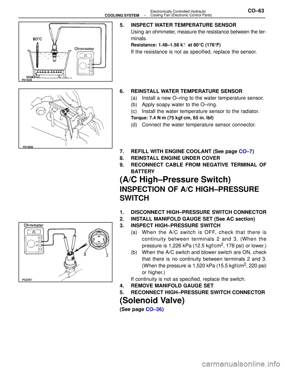
5. INSPECT WATER TEMPERATURE SENSORUsing an ohmmeter, measure the resistance between the ter-
minals.
Resistance: 1.48±1.58 k � at 80 5C (176 5F)
If the resistance is not as specified, replace the sensor.
6. REINSTALL WATER TEMPERATURE SENSOR (a) Install a new O±ring to the water temperature sensor.
(b) Apply soapy water to the O±ring.
(c) Install the water temperature sensor to the radiator.
Torque: 7.4 N Vm (75 kgf Vcm, 65 in. Vlbf)
(d) Connect the water temperature sensor connector.
7. REFILL WITH ENGINE COOLANT (See page CO±7)
8. REINSTALL ENGINE UNDER COVER
9. RECONNECT CABLE FROM NEGATIVE TERMINAL OF BATTERY
(A/C High±Pressure Switch)
INSPECTION OF A/C HIGH±PRESSURE
SWITCH
1. DISCONNECT HIGH±PRESSURE SWITCH CONNECTOR
2. INSTALL MANIFOLD GAUGE SET (See AC section)
3. INSPECT HIGH±PRESSURE SWITCH(a) Wh e n th e A/C switch is OFF, ch e ck th a t th e re iscontinuity between terminals 2 and 3. (When the
pressure is 1,226 kPa (12.5 kgf/cm
2, 178 psi) or lower.)
(b) When the A/C switch and blower switch are ON, check
that there is no continuity between terminals 2 and 3.
(When the pressure is 1,520 kPa (15.5 kgf/cm
2, 220 psi)
or higher.)
If continuity is not as specified, replace the switch.
4. REMOVE MANIFOLD GAUGE SET
5. RECONNECT HIGH±PRESSURE SWITCH CONNECTOR
(Solenoid Valve)
(See page CO±36)
±
COOLIING SYSTEM Electronically Controlled Hydraulic
Cooling Fan (Electronic Control Parts)CO±63
WhereEverybodyKnowsYourName
Page 2851 of 4087
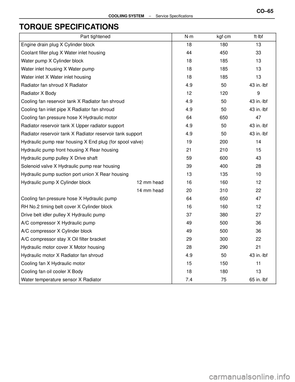
TORQUE SPECIFICATIONS
Part tightenedNVmkgf Vcmft Vlbf
Engine drain plug X Cylinder block1818013
Coolant filler plug X Water inlet housing44450 33
Water pump X Cylinder block18185 13
Water inlet housing X Water pump18185 13
Water inlet X Water inlet housing18185 13
Radiator fan shroud X Radiator4.950 43 in. Vlbf
Radiator X Body12120 9
Cooling fan reservoir tank X Radiator fan shroud4.950 43 in. Vlbf
Cooling fan inlet pipe X Radiator fan shroud4.950 43 in. Vlbf
Cooling fan pressure hose X Hydraulic motor64650 47
Radiator reservoir tank X Upper radiator support4.950 43 in. Vlbf
Radiator reservoir tank X Radiator reservoir tank support4.950 43 in. Vlbf
Hydraulic pump rear housing X End plug (for spool valve)19200 14
Hydraulic pump front housing X Rear housing21210 15
Hydraulic pump pulley X Drive shaft59600 43
Solenoid valve X Hydraulic pump rear housing39400 28
Hydraulic pump suction port union X Rear housing13135 10
����������������� �����������������Hydraulic pump X Cylinder block������ ������12 mm head����� �����16������ ������160������ ������12
����������������� ����������������������� ������14 mm head����� �����20������ ������310������ ������22
������������������\
���� ������������������\
����Cooling fan pressure hose X Hydraulic pump����� �����64������ ������650������ ������47
������������������\
���� ������������������\
����RH No.2 timing belt cover X Cylinder block����� �����16������ ������160������ ������12
������������������\
���� ������������������\
����Drive belt idler pulley X Hydraulic pump����� �����37������ ������380������ ������27
������������������\
���� ������������������\
����A/C compressor X Hydraulic pump����� �����49������ ������500������ ������36
������������������\
���� ������������������\
����A/C compressor X Cylinder block����� �����49������ ������500������ ������36������������������\
���� ������������������\
����A/C compressor stay X Oil filter bracket����� �����29������ ������300������ ������22������������������\
���� ������������������\
����Hydraulic motor cover X Motor housing����� �����28������ ������290������ ������21������������������\
���� �
������������������\
���
������������������\
����Hydraulic motor X Radiator fan shroud
����� �
����
�����4.9
������ �
�����
������50
������ �
�����
������43 in.
Vlbf
������������������\
���� ������������������\
����Cooling fan X Hydraulic motor����� �����15������ ������150������ ������11
������������������\
���� ������������������\
����Cooling fan oil cooler X Body����� �����18������ ������180������ ������13
������������������\
���� ������������������\
����Water temperature sensor X Radiator����� �����7.4������ ������75������ ������65 in. Vlbf
±
COOLIING SYSTEM Service SpecificationsCO±65
WhereEverybodyKnowsYourName
Page 2859 of 4087
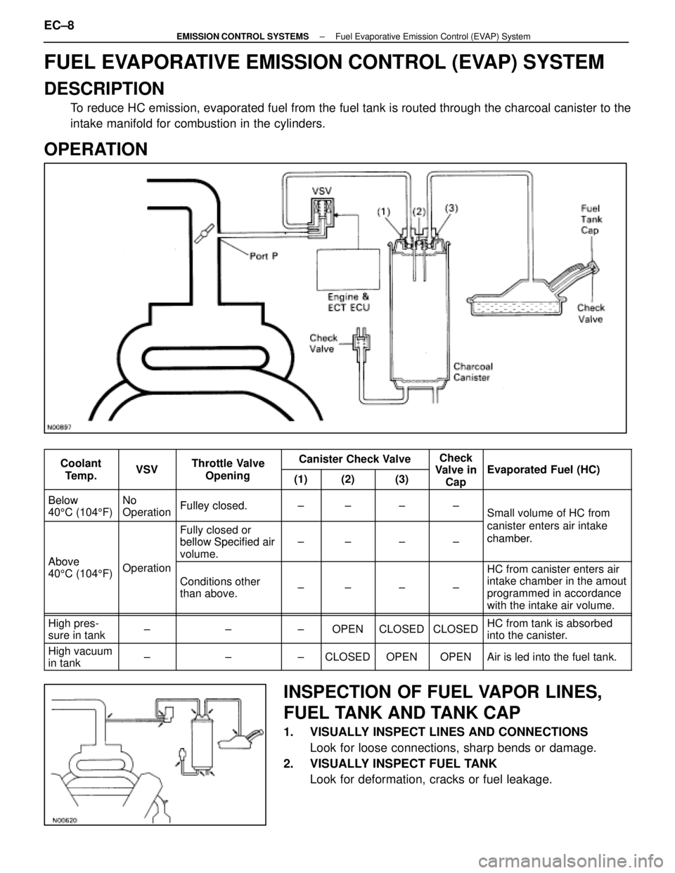
FUEL EVAPORATIVE EMISSION CONTROL (EVAP) SYSTEM
DESCRIPTION
To reduce HC emission, evaporated fuel from the fuel tank is routed throug\
h the charcoal canister to the
intake manifold for combustion in the cylinders.
OPERATION
CoolantVSVThrottle ValveCanister Check ValveCheck
Valve inEvaporated F el (HC)Coolant
Te m p .VSVThrottle Valve
Opening(1)(2)(3)Valve inCapEvaporated Fuel (HC)
BelowNoFulley closedBelow
40 5C (104 5F)
No
OperationFulley closed.±±±±Small volume of HC from
Fully closed or
bellow Specified air
canister enters air intake
chamber.
Above
bellow Specified air
volume.±±±±chamber.
Above
40 5C (104 5F)Operation
Conditions other
than above.±±±±
HC from canister enters air
intake chamber in the amout
programmed in accordance
with the intake air volume.
High pres-
sure in tank±±±OPENCLOSEDCLOSEDHC from tank is absorbed
into the canister.
High vacuum
in tank±±±CLOSEDOPENOPENAir is led into the fuel tank.
INSPECTION OF FUEL VAPOR LINES,
FUEL TANK AND TANK CAP
1. VISUALLY INSPECT LINES AND CONNECTIONS
Look for loose connections, sharp bends or damage.
2. VISUALLY INSPECT FUEL TANK Look for deformation, cracks or fuel leakage.
EC±8
±
EMISSION CONTROL SYSTEMS Fuel Evaporative Emission Control (EVAP) System
WhereEverybodyKnowsYourName
Page 2866 of 4087
EXHAUST GAS RECIRCULATION (EGR) SYSTEM
DESCRIPTION
To reduce NOx emission, part of the exhaust gases are recirculated through\
the EGR valve to the intake
manifold to lower the maximum combustion temperature.
OPERATION
Coolant Temp.ConditionEGR ValveExhaust Gas
Below 53 5C (127 5F)±CLOSEDNot recirculated
Above 55 5C (131 5F)(a)Idling, Deceleration, Neutral,
Low air volume, High Engine speedCLOSEDNot recirculatedAbove 55 C (131 F)
Except (a)OPEN*Recirculated
* The ECU calculates the appropriate number of steps according to the in\
take air volume and the engine speed, then
drives the stepping motor to maintain the EGR volume at a level appropri\
ate to the driving conditions.
±
EMISSION CONTROL SYSTEMS Exhaust Gas Recirculation (EGR) SystemEC±15
WhereEverybodyKnowsYourName
Page 2868 of 4087
INSPECTION OF EGR SYSTEM (USA
Spec.)
INSPECT SYSTEM OPERATION
(a) Using SST, connect terminals TE1 and E1 of the check(ºDIAGNOSISº) connector.
SST 09843±18020
(b) Keep the engine at 3,500 rpm.
(c) Set the transmission shift lever to the ºNº position.
(d) Remove the SST from the check connector.
SST 09843±18020
(e) Check whether the engine rpm increases 100±300 rpm under the following conditions.
Coolant temp.
Below 53 5C (127 5F) No increase
Above 55 5C (131 5F) Increases
±
EMISSION CONTROL SYSTEMS Exhaust Gas Recirculation (EGR) SystemEC±17
WhereEverybodyKnowsYourName
Page 2869 of 4087
INSPECTION OF EGR SYSTEM
(Exc. USA Spec.)
1. CHECK AND CLEAN FILTERS IN EGR VACUUMMODULATOR
(a) Remove the cap and filter.
(b) Check the filter for contamination or damage.
(c) Using compressed air, clean the filters.
(d) Reinstall the filter and cap.
HINT: Install the filter with the coarser surface facing the at-
mospheric side (outward).
2. INSPECT SYSTEM OPERATION (a) Using SST, connect terminals TE1 and E1 of the check
(ºDIAGNOSISº) connector.
SST 09843±18020
(b) Keep the engine at 3,500 rpm.
(c) Set the transmission shift lever to the ºNº position.
(d) Remove the SST from the check connector.
SST 09843±18020
(e) Check whether the engine rpm increases 100±300 rpm under the following conditions:
Coolant temp.
Below 53 5C (127 5F) No increase
Above 55 5C (131 5F) Increases
EC±18
±
EMISSION CONTROL SYSTEMS Exhaust Gas Recirculation (EGR) System
WhereEverybodyKnowsYourName
Page 2873 of 4087
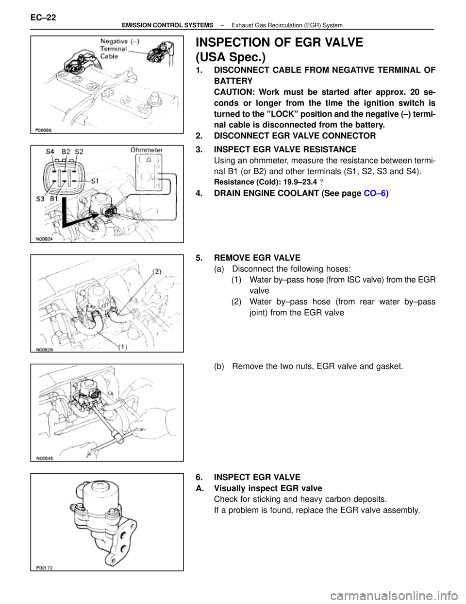
INSPECTION OF EGR VALVE
(USA Spec.)
1. DISCONNECT CABLE FROM NEGATIVE TERMINAL OFBATTERY
CAUTION: Work must be started after approx. 20 se-
conds or longer from the time the ignition switch is
turned to the ºLOCKº position and the negative (±) termi-
nal cable is disconnected from the battery.
2. DISCONNECT EGR VALVE CONNECTOR
3. INSPECT EGR VALVE RESISTANCE Using an ohmmeter, measure the resistance between termi-
nal B1 (or B2) and other terminals (S1, S2, S3 and S4).
Resistance (Cold): 19.9±23.4 �
4. DRAIN ENGINE COOLANT (See page CO±6)
5. REMOVE EGR VALVE (a) Disconnect the following hoses:(1) Water by±pass hose (from ISC valve) from the EGR
valve
(2) Water by±pass hose (from rear water by±pass joint) from the EGR valve
(b) Remove the two nuts, EGR valve and gasket.
6. INSPECT EGR VALVE
A. Visually inspect EGR valve Check for sticking and heavy carbon deposits.
If a problem is found, replace the EGR valve assembly.
EC±22
±
EMISSION CONTROL SYSTEMS Exhaust Gas Recirculation (EGR) System
WhereEverybodyKnowsYourName
Page 2875 of 4087
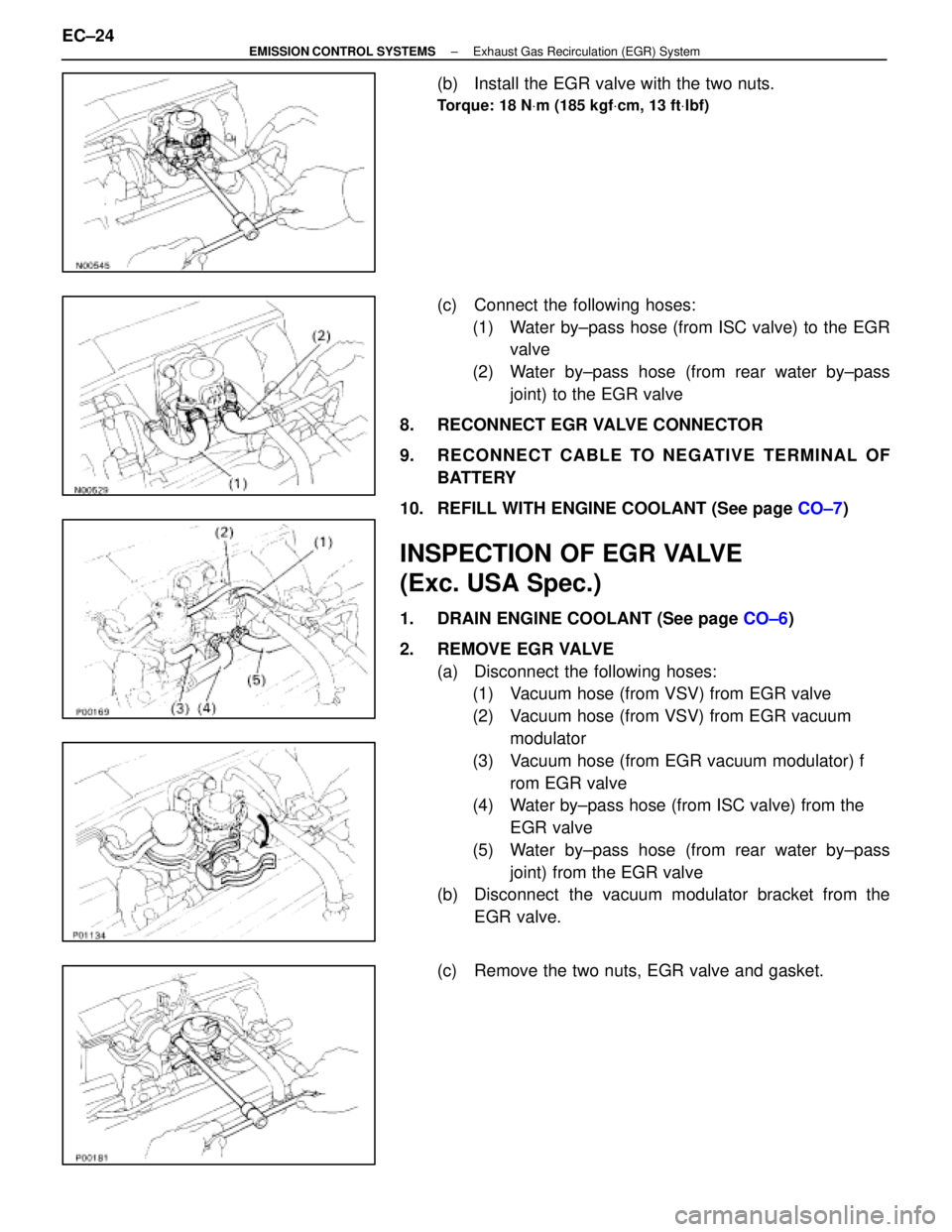
(b) Install the EGR valve with the two nuts.
Torque: 18 NVm (185 kgf Vcm, 13 ft Vlbf)
(c) Connect the following hoses:
(1) Water by±pass hose (from ISC valve) to the EGR valve
(2) Water by±pass hose (from rear water by±pass joint) to the EGR valve
8. RECONNECT EGR VALVE CONNECTOR
9. RECONNECT CABLE TO NEGATIVE TERMINAL OF BATTERY
10. REFILL WITH ENGINE COOLANT (See page CO±7)
INSPECTION OF EGR VALVE
(Exc. USA Spec.)
1. DRAIN ENGINE COOLANT (See page CO±6)
2. REMOVE EGR VALVE (a) Disconnect the following hoses:(1) Vacuum hose (from VSV) from EGR valve
(2) Vacuum hose (from VSV) from EGR vacuum
modulator
(3) Vacuum hose (from EGR vacuum modulator) f rom EGR valve
(4) Water by±pass hose (from ISC valve) from the
EGR valve
(5) Water by±pass hose (from rear water by±pass joint) from the EGR valve
(b) Disconnect the vacuum modulator bracket from the
EGR valve.
(c) Remove the two nuts, EGR valve and gasket.
EC±24
±
EMISSION CONTROL SYSTEMS Exhaust Gas Recirculation (EGR) System
WhereEverybodyKnowsYourName