Page 2388 of 4087

The EFI system is composed of three basic sub±systems: Fuel, Air Induction and Elect\
ronic Control
Systems.
FUEL SYSTEM
An electric pump fuel pressure supplies sufficient fuel, under a constant pressure, to the EFI injectors. In
accordance with signals from the ECU (Electronic Control Unit), these \
injectors inject the quantity of fuel most
appropriate for the engine condition into the intake manifold.
AIR INDUCTION SYSTEM
The air induction system provides sufficient air for engine operation.
ELECTRONIC CONTROL SYSTEM
The 1UZ±FE engine (ECU±formerly EFI computer) with a microcomputer \
centrally controls the EFI, ESA,
ISC and Diagnosis system, etc. The ECU controls the following functions:
1. Electronic Fuel Injection (EFI)
The ECU receives signals from various sensors indicating changing engine op\
eration conditions such as:Intake air volume
Intake air temperature
Coolant temperature
Engine rpm
Acceleration/deceleration
Exhaust oxygen content etc.
The signals are utilized by the ECU to determine the injection duration nec\
essary for an optimum air±fuel
ratio.
2. Electronic Spark Advance (ESA) The ECU is programmed with data for optimum ignition timing under any and all opera\
ting conditions. Using
data provided by sensors which monitor various engine functions (rpm, coola\
nt temperature, etc.), the
Electronic Control Unit (ECU) triggers the spark at precisely right instant. (S\
ee IG section)
3. Idle Speed Control (ISC) The ECU is programmed with idle speed data for various engine conditions (\
coolant temperature, air condi-
tioner ON/OFF, etc.).
The air volume flowing through the throttle valve by±pass passage is adj\
usted according to the signal from
each sensor and the idle speed is kept at the set value.
4. Diagnosis Function When the ECU detects any malfunctions or abnormalities in the sensor network\
, it lights the ºCHECKº en-
gine warning light in the combination meter. At the same time, the trouble is identified and a diagnostic code
is recorded by the ECU. The diagnostic code can be read by the number of\
blinks of the ºCHECKº engine
warning light when terminals TE1 and E1 are connected. The diagnostic co\
des are refer to the later page.
(See TR section)
5. Self±Correction Function If any sensor malfunctions, an average value recorded in the back±up ci\
rcuit is substituted to make driving
possible.
If danger is predicted, the engine is stopped and the ºCHECKº engine\
warning light will light up.
6. Fail±Safe Function Even if an abnormality occurs in the ECU, the back±up circuit uses a specifie\
d fuel injection and ignition
timing to provide vehicle driveability, and also lightsup the ºCHECKº engine warning light.
FI±4
EFI SYSTEM
± Description
WhereEverybodyKnowsYourName
Page 2391 of 4087

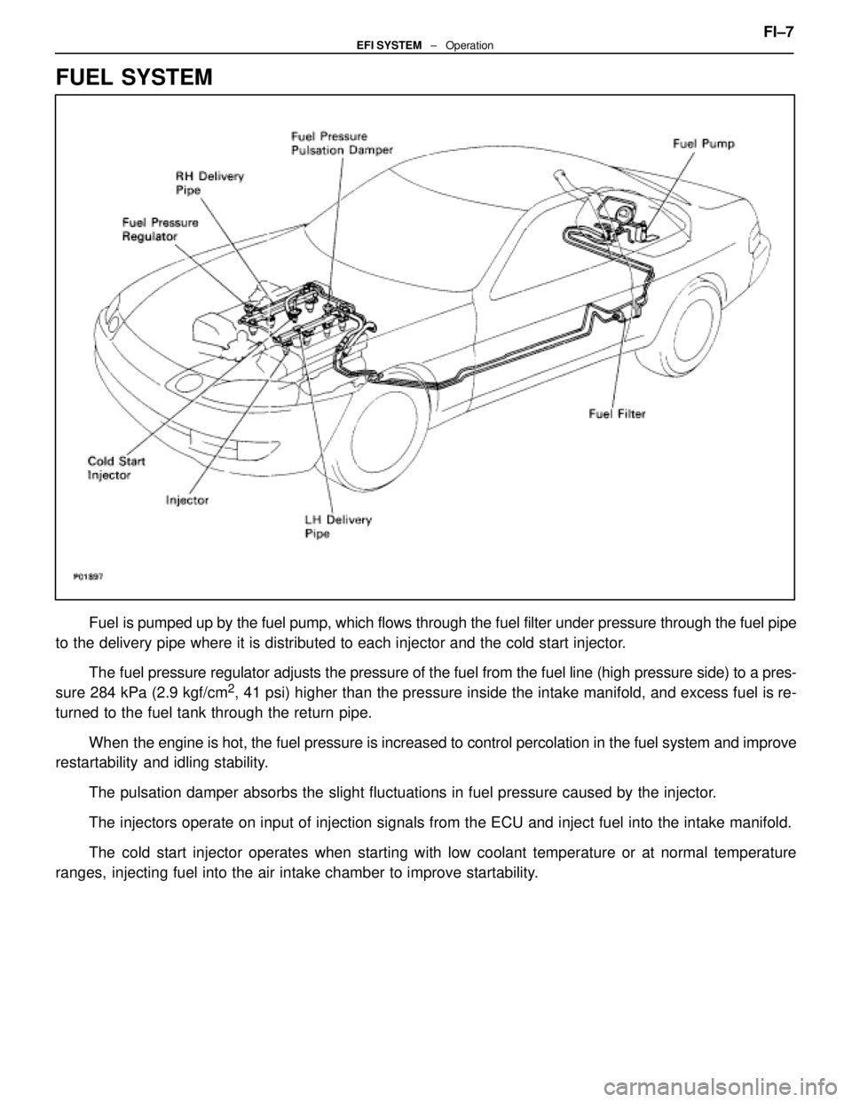
FUEL SYSTEM
Fuel is pumped up by the fuel pump, which flows through the fuel filter under pr\
essure through the fuel pipe
to the delivery pipe where it is distributed to each injector and the cold\
start injector.
The fuel pressure regulator adjusts the pressure of the fuel from the fuel \
line (high pressure side) to a pres-
sure 284 kPa (2.9 kgf/cm
2, 41 psi) higher than the pressure inside the intake manifold, and exce\
ss fuel is re-
turned to the fuel tank through the return pipe.
When the engine is hot, the fuel pressure is increased to control percolatio\
n in the fuel system and improve
restartability and idling stability.
The pulsation damper absorbs the slight fluctuations in fuel pressure ca\
used by the injector.
The injectors operate on input of injection signals from the ECU and inj\
ect fuel into the intake manifold.
The cold start injector operates when starting with low coolant temperature or at normal temperature
ranges, injecting fuel into the air intake chamber to improve startability. FI±7
EFI SYSTEM
± Operation
WhereEverybodyKnowsYourName
Page 2393 of 4087
ELECTRONIC CONTROL SYSTEM
The control system consists of sensors which detect various engine conditions, and a ECU which deter\
-
mines the injection volume (timing) based on the signals from the sens\
ors.
The various sensors detect the air intake volume, engine rpm, oxygen densit\
y in the exhaust gas, coolant
temperature, air intake temperature and atmospheric pressure etc. and convert the in\
formation into an electrical
signal which is sent to the ECU. Based on these signals, the ECU calculates th\
e optimum ignition timing for the
current conditions and operates the injectors.
The ECU not only controls the fuel injection timing, but also the self diag\
nostic function which records the
occurrence of a malfunction, ignition timing control, idle rpm control, \
EGR control, EVAP control, fuel pressure
control and fuel pump control. FI±9
EFI SYSTEM
± Operation
WhereEverybodyKnowsYourName
Page 2407 of 4087

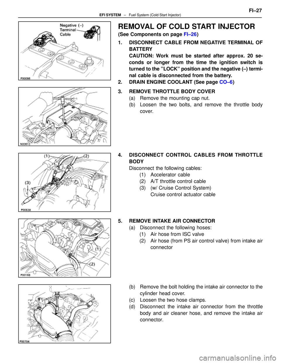
REMOVAL OF COLD START INJECTOR
(See Components on page FI±26)
1. DISCONNECT CABLE FROM NEGATIVE TERMINAL OF BATTERY
CAUTION: Work must be started after approx. 20 se-
conds or longer from the time the ignition switch is
turned to the ºLOCKº position and the negative (±) termi-
nal cable is disconnected from the battery.
2. DRAIN ENGINE COOLANT (See page CO±6)
3. REMOVE THROTTLE BODY COVER (a) Remove the mounting cap nut.
(b) Loosen the two bolts, and remove the throttle bodycover.
4. DISCONNECT CONTROL CABLES FROM THROTTLE BODY
Disconnect the following cables:(1) Accelerator cable
(2) A/T throttle control cable
(3) (w/ Cruise Control System)
Cruise control actuator cable
5. REMOVE INTAKE AIR CONNECTOR (a) Disconnect the following hoses:(1) Air hose from ISC valve
(2) Air hose (from PS air control valve) from intake air connector
(b) Remove the bolt holding the intake air connector to the cylinder head cover.
(c) Loosen the two hose clamps.
(d) Disconnect the intake air connector from the throttle body and air cleaner hose, and remove the intake air
connector. FI±27
EFI SYSTEM
± Fuel System (Cold Start Injector)
WhereEverybodyKnowsYourName
Page 2421 of 4087

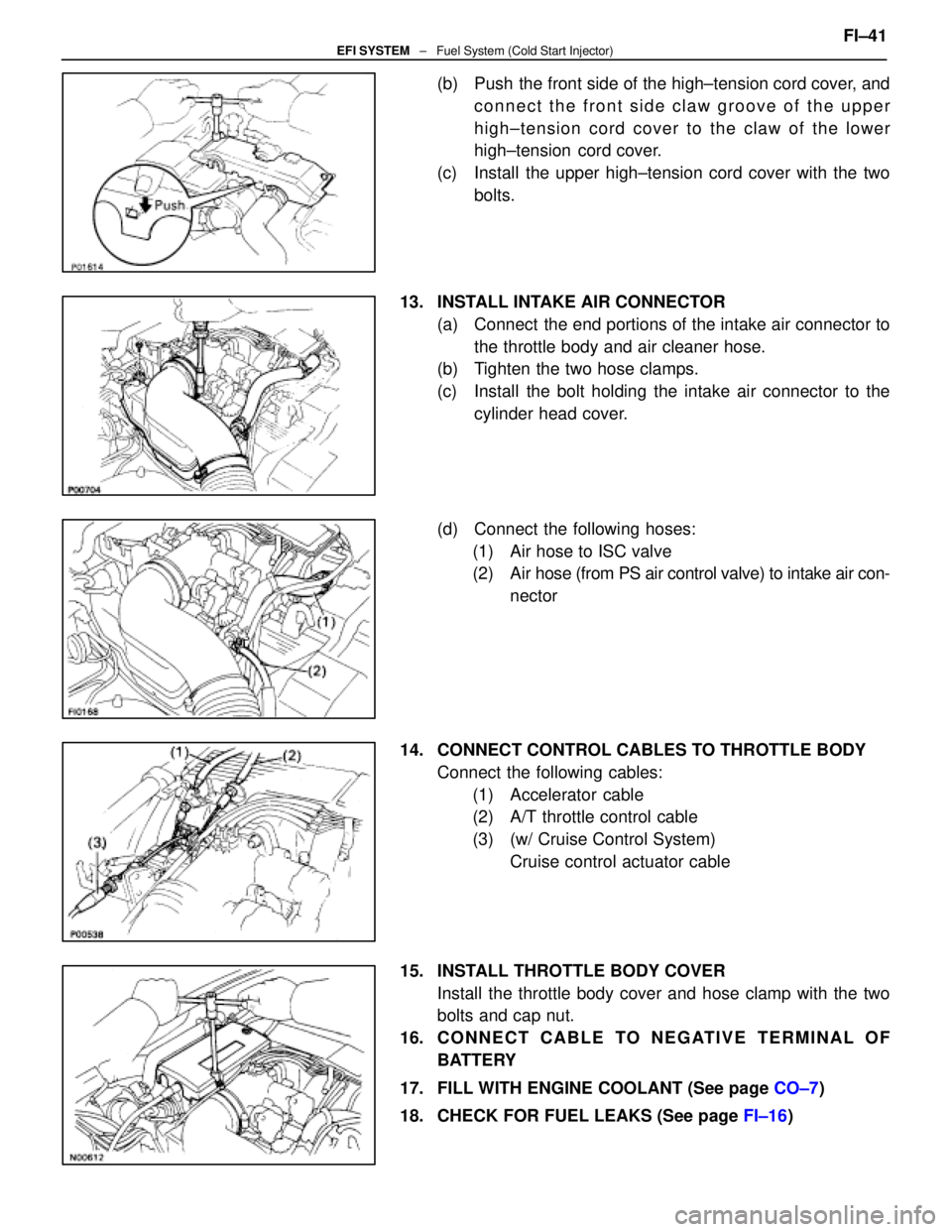
(b) Push the front side of the high±tension cord cover, andconnect the front side claw groove of the upper
high±tension cord cover to the claw of the lower
high±tension cord cover.
(c) Install the upper high±tension cord cover with the two bolts.
13. INSTALL INTAKE AIR CONNECTOR (a) Connect the end portions of the intake air connector tothe throttle body and air cleaner hose.
(b) Tighten the two hose clamps.
(c) Install the bolt holding the intake air connector to the
cylinder head cover.
(d) Connect the following hoses: (1) Air hose to ISC valve
(2) Air hose (from PS air control valve) to intake air con- nector
14. CONNECT CONTROL CABLES TO THROTTLE BODY Connect the following cables:(1) Accelerator cable
(2) A/T throttle control cable
(3) (w/ Cruise Control System) Cruise control actuator cable
15. INSTALL THROTTLE BODY COVER Install the throttle body cover and hose clamp with the two
bolts and cap nut.
16. C O N N E C T C A B L E TO N E G AT I V E T E R M I N A L O F BATTERY
17. FILL WITH ENGINE COOLANT (See page CO±7)
18. CHECK FOR FUEL LEAKS (See page FI±16) FI±41
EFI SYSTEM
± Fuel System (Cold Start Injector)
WhereEverybodyKnowsYourName
Page 2450 of 4087

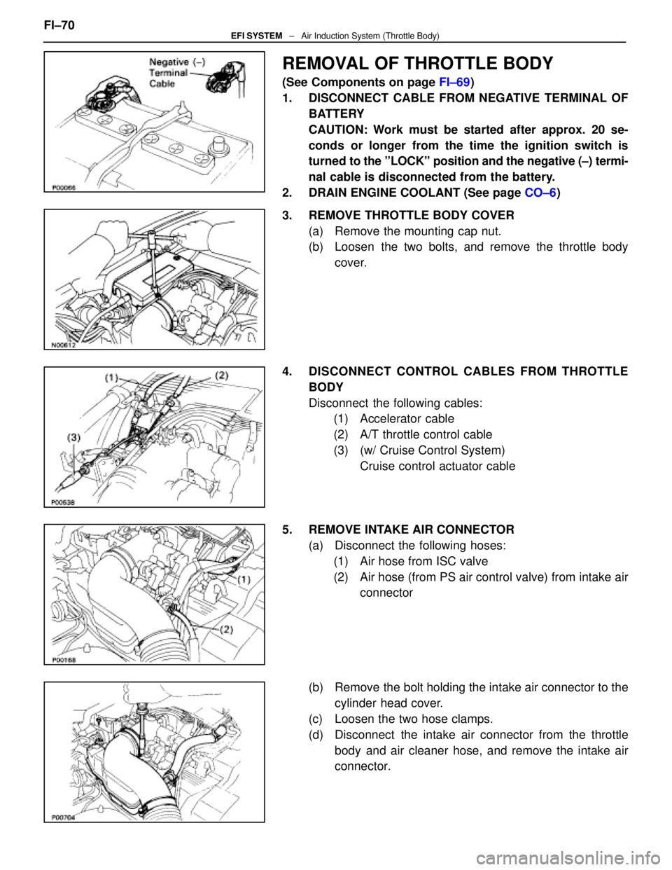
REMOVAL OF THROTTLE BODY
(See Components on page FI±69)
1. DISCONNECT CABLE FROM NEGATIVE TERMINAL OF BATTERY
CAUTION: Work must be started after approx. 20 se-
conds or longer from the time the ignition switch is
turned to the ºLOCKº position and the negative (±) termi-
nal cable is disconnected from the battery.
2. DRAIN ENGINE COOLANT (See page CO±6)
3. REMOVE THROTTLE BODY COVER (a) Remove the mounting cap nut.
(b) Loosen the two bolts, and remove the throttle bodycover.
4. DISCONNECT CONTROL CABLES FROM THROTTLE BODY
Disconnect the following cables:(1) Accelerator cable
(2) A/T throttle control cable
(3) (w/ Cruise Control System)
Cruise control actuator cable
5. REMOVE INTAKE AIR CONNECTOR (a) Disconnect the following hoses:(1) Air hose from ISC valve
(2) Air hose (from PS air control valve) from intake air connector
(b) Remove the bolt holding the intake air connector to the cylinder head cover.
(c) Loosen the two hose clamps.
(d) Disconnect the intake air connector from the throttle body and air cleaner hose, and remove the intake air
connector.
FI±70
EFI SYSTEM
± Air Induction System (Throttle Body)
WhereEverybodyKnowsYourName
Page 2459 of 4087
(d) Connect the following hoses:(1) Air hose to ISC valve
(2) Air hose (from PS air control valve) to intake air con-
nector
4. CONNECT CONTROL CABLES TO THROTTLE BODY Connect the following cables:(1) Accelerator cable
(2) A/T throttle control cable
(3) (w/ Cruise Control System) Cruise control actuator cable
5. INSTALL THROTTLE BODY COVER Install the throttle body cover and hose clamp with the two
bolts and cap nut.
6. CONNECT CABLE TO NEGATIVE TERMINAL OF BATTERY
7. FILL WITH ENGINE COOLANT (See page CO±7)FI±79
EFI SYSTEM
± Air Induction System (Throttle Body)
WhereEverybodyKnowsYourName
Page 2483 of 4087
INSPECTION OF EGR GAS
TEMPERATURE SENSOR
1. DISCONNECT CABLE FROM NEGATIVE TERMINAL OFBATTERY
CAUTION: Work must be started after approx. 20 se-
conds or longer from the time the ignition switch is
turned to the ºLOCKº position and the negative (±) termi-
nal cable is disconnected from the battery.
2. DRAIN ENGINE COOLANT
3. REMOVE EGR VALVE (a) Disconnect the EGR gas temperature sensor.
(b) Disconnect the following hoses from the EGR valve:(1) Water by±pass hose (from ISC valve)
(2) Water by±pass hose (from rear water by±pass joint)
(c) Remove the two nuts, EGR valve and gasket.
4. REMOVE EGR VALVE ADAPTOR (a) Disconnect the EGR gas temperature sensor.
(b) Disconnect the PCV hose from the EGR valve adaptor.
(c) Remove the two bolts, two nuts, EGR valve adaptor andgasket. FI±103
EFI SYSTEM
± Electronic Control System (EGR Gas Temperature Sensor (USA Spec. only))
WhereEverybodyKnowsYourName