Page 2514 of 4087

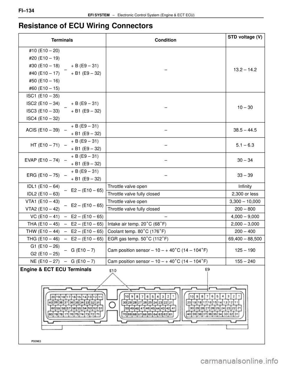
Resistance of ECU Wiring Connectors
TerminalsConditionSTD voltage (V)
#10 (E10 ± 20)
#20 (E10 ± 19)
#30 (E10 ± 18)+ B (E9 ± 31)13 2 14 2#40 (E10 ± 17)±+ B1 (E9 ± 32) ±13.2 ± 14.2
#50 (E10 ± 16)
#60 (E10 ± 15)
ISC1 (E10 ± 35)
ISC2 (E10 ± 34)+ B (E9 ± 31)10 30ISC3 (E10 ± 33)±
+ B1 (E9 ± 32) ±10 ± 30
ISC4 (E10 ± 32)
ACIS (E10 39)+ B (E9 ± 31)38 5 44 5ACIS (E10 ± 39)±
+ B1 (E9 ± 32) ±38.5 ± 44.5
HT (E10 71)+ B (E9 ± 31)51 63HT (E10 ± 71)±
+ B1 (E9 ± 32) ±5.1 ± 6.3
EVAP (E10 74)+ B (E9 ± 31)30 34EVAP (E10 ± 74)±
+ B1 (E9 ± 32) ±30 ± 34
ERG (E10 75)+ B (E9 ± 31)33 39ERG (E10 ± 75)±
+ B1 (E9 ± 32) ±33 ± 39
IDL1 (E10 ± 64)E2 (E10 65)Throttle valve openInfinity
IDL2 (E10 ± 63)± E2 ± (E10 ± 65)Throttle valve fully closed2,300 or less
VTA1 (E10 ± 43)E2 (E10 65)Throttle valve open3,300 ± 10,000
VTA2 (E10 ± 42)± E2 ± (E10 ± 65)Throttle valve fully closed200 ± 800
VC (E10 ± 41)±E2 ± (E10 ± 65)±4,000 ± 9,000
THA (E10 ± 45)±E2 ± (E10 ± 65)Intake air temp. 20
°C (68 °F)2,000 ± 3,000
THW (E10 ± 44)±E2 ± (E10 ± 65)Coolant temp. 80 °C (176 °F)200 ± 400
THG (E10 ± 46)±E2 ± (E10 ± 65)EGR gas temp. 50 °C (112 °F)69,400 ± 88,500
G1 (E10 ± 26)G (E10 7)Camposition sensor 10 + 40°C (14 104°F)125 190G2 (E10 ± 25)±G (E10 ± 7)Cam position sensor ± 10 ± + 40°C (14 ± 104°F)125 ± 190
NE (E10 ± 27)±G (E10 ± 7)Cam position sensor ± 10 ± + 40 °C (14 ± 104 °F)155 ± 240
Engine & ECT ECU Terminals
FI±134EFI SYSTEM ± Electronic Control System (Engine & ECT ECU)
WhereEverybodyKnowsYourName
Page 2515 of 4087
wDisconnect the SST from the wiring connectors.
SST 09990±01000
4. REINSTALL ENGINE & ECT ECU TO FLOOR PANEL
(a) Connect the two ECU connectors.w Match the male connector correctly with the female
connector, then press them together.
w Tighten the bolt.
Make sure the connector is completely connected, by tight-
ening the bolt until there is a clearance of less than 1 mm
(0.04 in.) between bottom of the male connector and end of
the female connector.
(b) Install the ECU with the bolt.
(c) Install the ECU protector with the two nuts.
(d) Install the floor carpet.
(e) Install the instrument panel under cover with the two clips.
5. RECONNECT CABLE TO NEGATIVE TERMINAL OF BATTERY FI±135
EFI SYSTEM
± Electronic Control System (Engine & ECT ECU)
WhereEverybodyKnowsYourName
Page 2516 of 4087
Fuel Cut RPM
INSPECTION OF FUEL CUT RPM
1. WARM UP ENGINEAllow the engine to warm up to normal operating
temperature.
2. CONNECT TACHOMETER Connect the test probe of a tachometer to terminal IG of the
check connector.
NOTICE
w Never allow the tachometer terminal to touch ground as
it could result in damage to the igniter and/or ignition
coil.
w As some tachometers are not compatible with this
ignition system, we recommend that you confirm the
compatibility of yours before use.
3. INSPECT FUEL CUT OPERATION
(a) Increase the engine speed to at least 2,500 rpm.
(b) Check for injector operating noise.
(c) Check that when the throttle lever is released, injectoroperation noise stops momentarily and then resumes.
HINT:
w The vehicle should be stopped.
w Measure with the A/C OFF.
Fuel return rpm: 1,400 rpm
4. REMOVE TACHOMETER
FI±136
± Electronic Control System (Fuel \
Cut RPM)EFI SYSTEM
WhereEverybodyKnowsYourName
Page 2518 of 4087

SERVICE DATA (Cont'd)
Water temp.
sensorResistanceat ±20°C (±4 °F)
at 0 °C (32 °F)
at 20 °C (68 °F)
at 40 °C (104 °F)
at 60 °C (140 °F)
at 80 °C (176 °F)10 ± 20 k �
4 ± 7 k �
2 ± 7 k �
0.9 ± 1.3 k �
0.4 ± 0.7 k �
0.2 ± 0.4 k �
EGR gas
temp.
sensorResistanceat 50°C (112 °F)
at 100 °C (212 °F)
at 150 °C (302 °F)69 ± 89 k �
12 ± 15 k �
2 ± 4 k �
Main oxygen
sensorHeater coil resistance5.1 ± 6.3 �
Sub±oxygen
sensorHeater coil resistance5.1 ± 6.3 �
ECUHINT:
�Perform all voltage and resistance measurements with the ECU connected.
� Verify that the battery voltage in 11 V or above with the ignition switch is ON.
Voltage
TerminalsConditionSTD voltage (V)
BATT ± E1±10 ± 14
IGSW
+B ± E1
+B1
IG SW ON10 ± 14
VC ± E2±4.0 ± 6.0
IDL1E2
Throttle (or sub±throttle) valve fully closed1 or lessIDL1
IDL2 ± E2
IG SW ONThrottle (or sub±throttle) valve fully open10 ± 14
VTA1E2
Throttle (or sub±throttle) valve fully closed0.1 or lessVTA1
VTA 2 ± E2
Throttle (or sub±throttle) valve fully open3.0 ± 6.0
KS ± E1IdlingPulse generation
THA ± E2
THW±E2Idling
Intake air temp. 20
°C (68 °F)1.0 ± 3.0
THW ± E2IdlingEngine coolant temp. 80 °C (176 °F)0.1 ± 1.0
STA ± E1Cranking6.0 or more
#10
#20
E01IG SW ON10 ± 14#20
#30
#40±
E01
E02IdlingPulse generation
IGT1
IGT2
± E1IdlingPulse generation
FI±138EFI SYSTEM
± Service Specifications
WhereEverybodyKnowsYourName
Page 2519 of 4087

SERVICE DATA (Cont'd)
ECU (cont'd)Voltage (cont'd)
TerminalsConditionSTD voltage (V)
IGF1E1
IG SW ON1.0 or lessIGF1
IGF2± E1
IdlingPulse generation
G1
G2 G1 (±)
G2 (±)
±IdlingPulse generation
NE ± NE (+)IdlingPulse generation
M±REL ± E1IG SW ON10 ± 14
FPC E1
Cracking, Sudden racing (6,000 rpm)4.2 ± 6.0
FPC ± E1
IdlingPulse generation
DI ± E1Idling7.5 or more
FPU E1
IG SW ON10 ± 14
FPU ± E1
Restarting high temp.2.0 or less
PAG ± E1IG SW ON10 ± 14
ISC1
ISC2
ISC3
ISC4 ± E1
IG SW ON10 ± 14
VF1
VF2
± E1Maintain engine speed at 2,500 rpm for 120 seconds
after warming up then return to idling.1.0 ± 4.0
OXR1
OXL1 ± E1Maintain engine speed at 2,500 rpm for 120 seconds
after warming upPulse generation
(0 ± 1.0)
HTR1
HTR2 E01IG SW ON10 ± 14HTR2
HTL1
HTL2±
E01
E02Idling2.0 or less
EGR1
EGR2
EGR3
EGR4 ± E1
IG SW ON10 ± 14
EGR ± E1Idling10 ± 14
KNK1
KNK2
± E1IdlingPulse generation
NSW E1IG SW ON
Shift position ºPº or ºNº range1.0 or less
NSW ± E1IG SW ON
Ex. shift position ºPº or ºNº range10 ± 14
FI±139EFI SYSTEM
± Service Specifications
WhereEverybodyKnowsYourName
Page 2521 of 4087
SERVICE DATA (Cont'd)
ECU (cont'd)Resistance of wiring connector side (cont'd)
TerminalsConditionSTD voltage (�)
±
HTR1
HTR2
HTL1
HTL2 +B
+B1±5.1 ± 6.3
±
PA G +B
+B1±30 ± 34
±IDL1 +BThrottle valve fully openInfinity
±IDL1
IDL2
+B
+B1Throttle valve fully closed2,300 or less
±VTA1E2
Throttle valve fully open3,300 ± 10,000
±VTA1
VTA2E2
Throttle valve fully closed200 ± 800
VC ± E2±4,000 ± 9,000
THS ± E2Intake air temp, 20
°C (68 °F)2,000 ± 3,000
THW ± E2Coolant temp. 80 °C (176 °F)200 ± 400
THG ± E2EGR gas temp. 50 °C (112 °F)69,400 ± 88,500
G1
G2 G1 (±)
G2 (±)
±Cam position sensor ± 10 ± +40
°C (14 ± 104 °F)835 ± 1,350
NE ± NE (±)engine speed sensor ± 10 ± +40 °C (14 ± 104 °F)835 ± 1,350
Fuel cut rpmw/ Vehicle speed 0 km/h and coolant temp. 80 °C (176 °F)
Fuel cut rpm
Fuel return rpm
1,800 rpm
1,400 rpm
FI±141EFI SYSTEM ± Service Specifications
WhereEverybodyKnowsYourName
Page 2524 of 4087

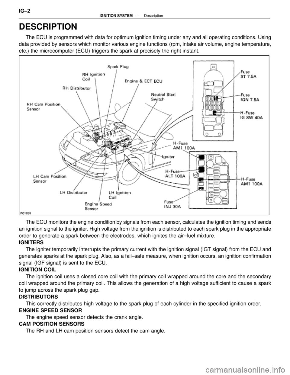
DESCRIPTION
The ECU is programmed with data for optimum ignition timing under any and a\
ll operating conditions. Using
data provided by sensors which monitor various engine functions (rpm, i\
ntake air volume, engine temperature,
etc.) the microcomputer (ECU) triggers the spark at precisely the right ins\
tant.
The ECU monitors the engine condition by signals from each sensor, calculates the ignition timing and sends
an ignition signal to the igniter. High voltage from the ignition is distributed to each spark plug in th\
e appropriate
order to generate a spark between the electrodes, which ignites the air±fu\
el mixture.
IGNITERS The igniter temporarily interrupts the primary current with the ignition si\
gnal (IGT signal) from the ECU and
generates sparks at the spark plug. Also, as a fail±safe measure, when ignitio\
n occurs, an ignition confirmation
signal (IGF signal) is sent to the ECU.
IGNITION COIL
The ignition coil uses a closed core coil with the primary coil wrapped \
around the core and the secondary
coil wrapped around the primary coil. This allows the generation of a hi\
gh voltage sufficient to cause a spark
to jump across the spark plug gap.
DISTRIBUTORS
This correctly distributes high voltage to the spark plug of each cylind\
er in the specified ignition order.
ENGINE SPEED SENSOR The engine speed sensor detects the crank angle.
CAM POSITION SENSORS The RH and LH cam position sensors detect the cam angle.
IG±2
±
IGNITION SYSTEM Description
WhereEverybodyKnowsYourName
Page 2525 of 4087
PRECAUTIONS
1. Do not leave the ignition switch on for more than 10minutes if the engine will not start.
2. With a tachometer connected to the system, connect the tester probe of the tachometer to terminal IG
of the
check (ºDIAGNOSISº) connector.
HINT:
wAllow the engine to warm up to normal operation
temperature.
w Set the tachometer to the 4±cylinder range.
3. As some tachometers are not compatible with this ignition system, we recommend that you confirm the
compatibility of your unit before use.
4. Never allow the tachometer terminal to touch ground as this could damage the igniter and/or ignition coil.
5. Do not disconnect the battery when the engine is running.
6. Check that the igniter is properly grounded to the body.
±
IGNITION SYSTEM PrecautionsIG±3
WhereEverybodyKnowsYourName