Page 2527 of 4087
PREPARATION
SST (SPECIAL SERVICE TOOLS)
RECOMMENDED TOOLS
EQUIPMENT
Part NameNote
Engine tune±up testerIgnition timing
Megger (Insulation resistance meter)Spark plug
Spark plug cleaner
Torque wrench
16 mm plug wrench
±
IGNITION SYSTEM PreparationIG±5
WhereEverybodyKnowsYourName
Page 2528 of 4087
ON±VEHICLE INSPECTION
SPARK TEST
CHECK THAT SPARK OCCURS(a) Remove the No.3 timing belt covers.(See steps 2 to 8 on pages IG±11 to 13)
(b) Disconnect the high±tension cords (from the ignition
coils) from the distributor caps.
(c) Hold the end about 12.5 mm (0.50 in.) from the body ground.
(d) Check if spark occurs while engine is being cranked.
HINT: To prevent gasoline from being injected from injectors
during this test, crank the engine for no more than 1±2 se-
conds at a time.
If the spark does not occur, perform the test as follows:
(e) Reconnect the high±tension cords to the distributor caps.
(f) Reinstall the No.3 timing belt covers. (See steps 5 to 11 on pages IG±17 to 19)
IG±6
±
IGNITION SYSTEM On±Vehicle Inspection
WhereEverybodyKnowsYourName
Page 2529 of 4087

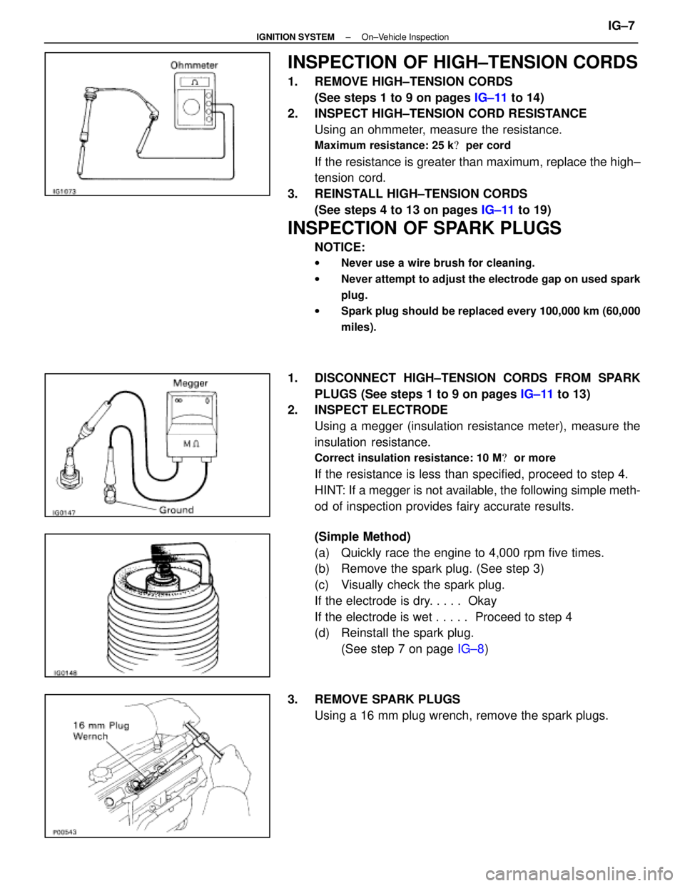
INSPECTION OF HIGH±TENSION CORDS
1. REMOVE HIGH±TENSION CORDS(See steps 1 to 9 on pages IG±11 to 14)
2. INSPECT HIGH±TENSION CORD RESISTANCE
Using an ohmmeter, measure the resistance.
Maximum resistance: 25 k � per cord
If the resistance is greater than maximum, replace the high±
tension cord.
3. REINSTALL HIGH±TENSION CORDS (See steps 4 to 13 on pages IG±11 to 19)
INSPECTION OF SPARK PLUGS
NOTICE:
wNever use a wire brush for cleaning.
w Never attempt to adjust the electrode gap on used spark
plug.
w Spark plug should be replaced every 100,000 km (60,000
miles).
1. DISCONNECT HIGH±TENSION CORDS FROM SPARK
PLUGS (See steps 1 to 9 on pages IG±11 to 13)
2. INSPECT ELECTRODE
Using a megger (insulation resistance meter), measure the
insulation resistance.
Correct insulation resistance: 10 M � or more
If the resistance is less than specified, proceed to step 4.
HINT: If a megger is not available, the following simple meth-
od of inspection provides fairy accurate results.
(Simple Method)
(a) Quickly race the engine to 4,000 rpm five times.
(b) Remove the spark plug. (See step 3)
(c) Visually check the spark plug.
If the electrode is dry. . . . . Okay
If the electrode is wet . . . . . Proceed to step 4
(d) Reinstall the spark plug.
(See step 7 on page IG±8)
3. REMOVE SPARK PLUGS Using a 16 mm plug wrench, remove the spark plugs.
±
IGNITION SYSTEM On±Vehicle InspectionIG±7
WhereEverybodyKnowsYourName
Page 2532 of 4087

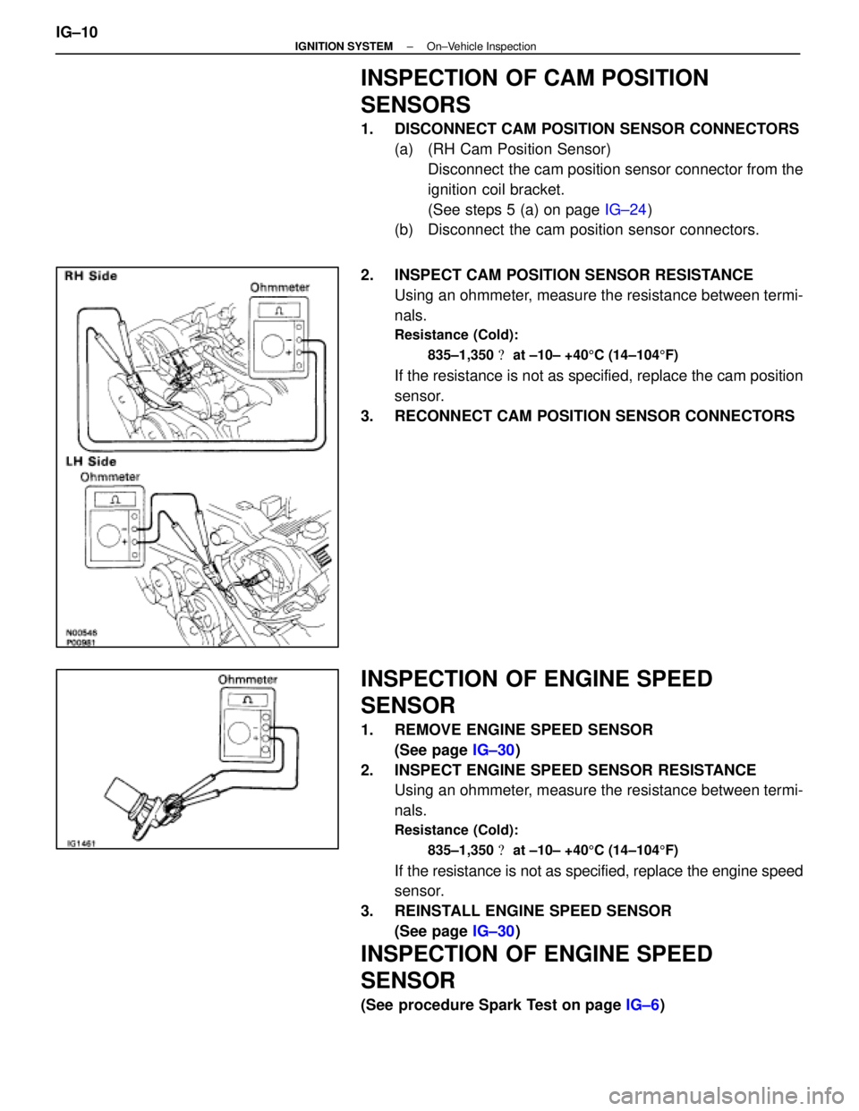
INSPECTION OF CAM POSITION
SENSORS
1. DISCONNECT CAM POSITION SENSOR CONNECTORS(a) (RH Cam Position Sensor)Disconnect the cam position sensor connector from the
ignition coil bracket.
(See steps 5 (a) on page IG±24)
(b) Disconnect the cam position sensor connectors.
2. INSPECT CAM POSITION SENSOR RESISTANCE Using an ohmmeter, measure the resistance between termi-
nals.
Resistance (Cold):
835±1,350 � at ±10± +40 5C (14±104 5F)
If the resistance is not as specified, replace the cam position
sensor.
3. RECONNECT CAM POSITION SENSOR CONNECTORS
INSPECTION OF ENGINE SPEED
SENSOR
1. REMOVE ENGINE SPEED SENSOR (See page IG±30)
2. INSPECT ENGINE SPEED SENSOR RESISTANCE Using an ohmmeter, measure the resistance between termi-
nals.
Resistance (Cold):
835±1,350 � at ±10± +40 5C (14±104 5F)
If the resistance is not as specified, replace the engine speed
sensor.
3. REINSTALL ENGINE SPEED SENSOR (See page IG±30)
INSPECTION OF ENGINE SPEED
SENSOR
(See procedure Spark Test on page IG±6)
IG±10
±
IGNITION SYSTEM On±Vehicle Inspection
WhereEverybodyKnowsYourName
Page 2534 of 4087
2. REMOVE INTAKE AIR CONNECTOR(a) Disconnect the following hoses:(1) Air hose from ISC valve
(2) Air hose (from PS air control valve) from intake air connector
(b) Remove the bolt holding the intake air connector to the cylinder head cover.
(c) Loosen the two hose clamps.
(d) Disconnect the intake air connector from the throttle
body and air cleaner hose, and remove the throttle body.
3. REMOVE UPPER HIGH±TENSION CORD COVER (a) Remove the two mounting bolts.
(b) Disconnect the front side claw groove of the cord coverfrom the claw of the lower cover, and remove the cord
cover.
4. REMOVE RH ENGINE WIRE COVER Remove the bolt and engine wire cover.
5. REMOVE LH ENGINE WIRE COVER Remove the two bolts and engine wire cover.
IG±12
±
IGNITION SYSTEM High±Tension Cords and Cord Clamps
WhereEverybodyKnowsYourName
Page 2540 of 4087

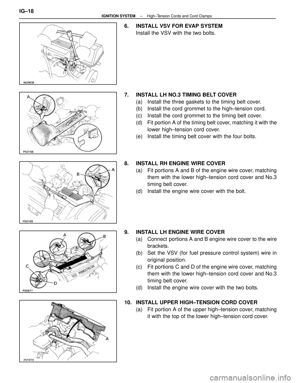
6. INSTALL VSV FOR EVAP SYSTEMInstall the VSV with the two bolts.
7. INSTALL LH NO.3 TIMING BELT COVER (a) Install the three gaskets to the timing belt cover.
(b) Install the cord grommet to the high±tension cord.
(c) Install the cord grommet to the timing belt cover.
(d) Fit portion A of the timing belt cover, matching it with the
lower high±tension cord cover.
(e) Install the timing belt cover with the four bolts.
8. INSTALL RH ENGINE WIRE COVER (a) Fit portions A and B of the engine wire cover, matchingthem with the lower high±tension cord cover and No.3
timing belt cover.
(d) Install the engine wire cover with the bolt.
9. INSTALL LH ENGINE WIRE COVER (a) Connect portions A and B engine wire cover to the wirebrackets.
(b) Set the VSV (for fuel pressure control system) wire in original position.
(c) Fit portions C and D of the engine wire cover, matching them with the lower high±tension cord cover and No.3
timing belt cover.
(d) Install the engine wire cover with the two bolts.
10. INSTALL UPPER HIGH±TENSION CORD COVER (a) Fit portion A of the upper high±tension cover, matchingit with the top of the lower high±tension cord cover.
IG±18
±
IGNITION SYSTEM High±Tension Cords and Cord Clamps
WhereEverybodyKnowsYourName
Page 2541 of 4087
(b) Push the front side of the high±tension cord cover, andconnect the front side claw groove of the upper
high±tension cord cover to the claw of the lower
high±tension cord cover.
(c) Install the upper high±tension cord cover with the two bolts.
11. INSTALL INTAKE AIR CONNECTOR (a) Connect the end portions of the intake air connector tothe throttle body and air cleaner hose.
(b) Tighten the two hose clamps.
(c) Install the bolt holding the intake air connector to the cylinder head cover.
(d) Connect the following hoses: (1) Air hose to ISC valve
(2) Air hose (from PS air control valve) to intake air con-
nector
12. CONNECT CABLE TO NEGATIVE TERMINAL OF BATTERY
13. CHECK THAT ENGINE STARTS
±
IGNITION SYSTEM High±Tension Cords and Cord ClampsIG±19
WhereEverybodyKnowsYourName
Page 2543 of 4087

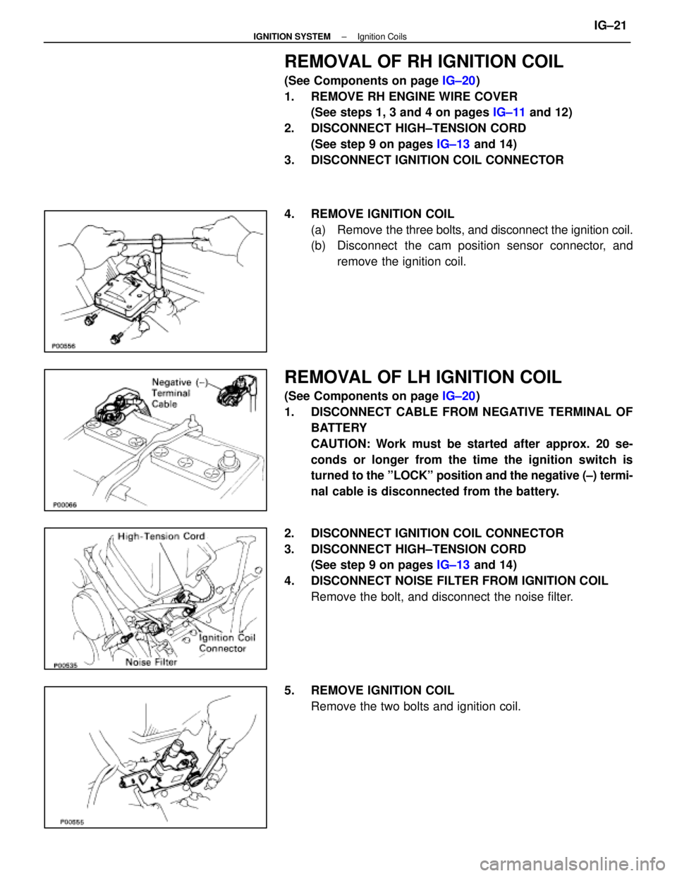
REMOVAL OF RH IGNITION COIL
(See Components on page IG±20)
1. REMOVE RH ENGINE WIRE COVER (See steps 1, 3 and 4 on pages IG±11 and 12)
2. DISCONNECT HIGH±TENSION CORD (See step 9 on pages IG±13 and 14)
3. DISCONNECT IGNITION COIL CONNECTOR
4. REMOVE IGNITION COIL (a) Remove the three bolts, and disconnect the ignition coil.
(b) Disconnect the cam position sensor connector, and
remove the ignition coil.
REMOVAL OF LH IGNITION COIL
(See Components on page IG±20)
1. DISCONNECT CABLE FROM NEGATIVE TERMINAL OF BATTERY
CAUTION: Work must be started after approx. 20 se-
conds or longer from the time the ignition switch is
turned to the ºLOCKº position and the negative (±) termi-
nal cable is disconnected from the battery.
2. DISCONNECT IGNITION COIL CONNECTOR
3. DISCONNECT HIGH±TENSION CORD (See step 9 on pages IG±13 and 14)
4. DISCONNECT NOISE FILTER FROM IGNITION COIL Remove the bolt, and disconnect the noise filter.
5. REMOVE IGNITION COIL Remove the two bolts and ignition coil.
±
IGNITION SYSTEM Ignition CoilsIG±21
WhereEverybodyKnowsYourName