Page 2568 of 4087

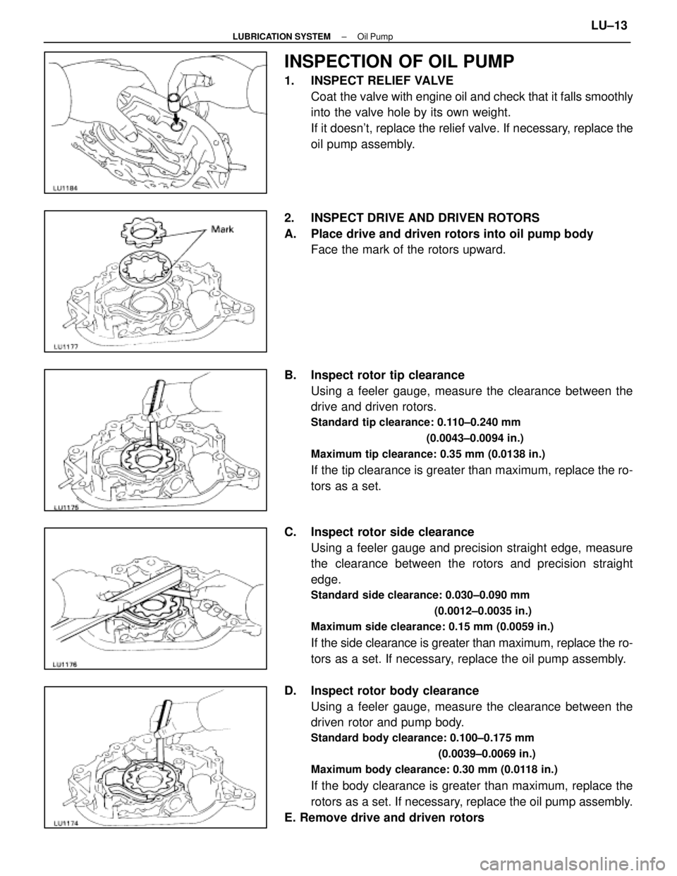
INSPECTION OF OIL PUMP
1. INSPECT RELIEF VALVECoat the valve with engine oil and check that it falls smoothly
into the valve hole by its own weight.
If it doesn't, replace the relief valve. If necessary, replace the
oil pump assembly.
2. INSPECT DRIVE AND DRIVEN ROTORS
A. Place drive and driven rotors into oil pump body Face the mark of the rotors upward.
B. Inspect rotor tip clearance Using a feeler gauge, measure the clearance between the
drive and driven rotors.
Standard tip clearance: 0.110±0.240 mm
(0.0043±0.0094 in.)
Maximum tip clearance: 0.35 mm (0.0138 in.)
If the tip clearance is greater than maximum, replace the ro-
tors as a set.
C. Inspect rotor side clearance Using a feeler gauge and precision straight edge, measure
the clearance between the rotors and precision straight
edge.
Standard side clearance: 0.030±0.090 mm
(0.0012±0.0035 in.)
Maximum side clearance: 0.15 mm (0.0059 in.)
If the side clearance is greater than maximum, replace the ro-
tors as a set. If necessary, replace the oil pump assembly.
D. Inspect rotor body clearance Using a feeler gauge, measure the clearance between the
driven rotor and pump body.
Standard body clearance: 0.100±0.175 mm
(0.0039±0.0069 in.)
Maximum body clearance: 0.30 mm (0.0118 in.)
If the body clearance is greater than maximum, replace the
rotors as a set. If necessary, replace the oil pump assembly.
E. Remove drive and driven rotors
±
LUBRICATION SYSTEM Oil PumpLU±13
WhereEverybodyKnowsYourName
Page 2571 of 4087
(e) Install the oil pump with the eight bolts.
Torque:12 mm head 16 N Vm (160 kgf Vcm, 12 ft Vlbf)
14 mm head 30 N Vm (310 kgf Vcm, 22 ft Vlbf)
HINT: Each bolt length is indicated in the illustration.
Bolt length:
A 50 mm (1.97 in.) for 12 mm head
B 106 mm (4.17 in.) for 12 mm head
C 30 mm (1.18 in.) for 12 mm head
D 40 mm (1.57 in.) for 14 mm head
2. INSTALL ENGINE SPEED SENSOR (a) Install the speed sensor with the bolt.
Torque: 6.4 N Vm (65 kgf Vcm, 56 in. Vlbf)
(b) Connect the speed sensor connector.
3. INSTALL OIL FILTER BRACKET (a) Place a new gasket in position on the oil filter bracket.
(b) Install the oil filter bracket with the two bolts and studbolt.
Torque: 18 N Vm (185 kgf Vcm, 13 ft Vlbf)
(c) Connect the oil pressure switch connector.
4. INSTALL OIL STRAINER Install a new gasket and the oil strainer with the two bolts and
two nuts.
Torque: 7.8 N Vm (80 kgf Vcm, 69 in. Vlbf)
LU±16±
LUBRICATION SYSTEM Oil Pump
WhereEverybodyKnowsYourName
Page 2574 of 4087

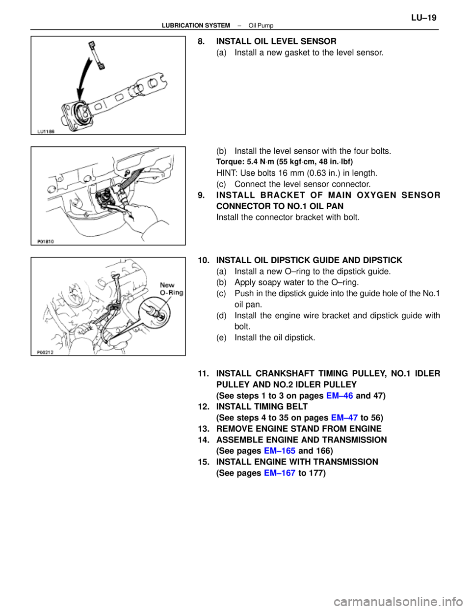
8. INSTALL OIL LEVEL SENSOR(a) Install a new gasket to the level sensor.
(b) Install the level sensor with the four bolts.
Torque: 5.4 N Vm (55 kgf Vcm, 48 in. Vlbf)
HINT: Use bolts 16 mm (0.63 in.) in length.
(c) Connect the level sensor connector.
9. INSTALL BRACKET OF MAIN OXYGEN SENSOR CONNECTOR TO NO.1 OIL PAN
Install the connector bracket with bolt.
10. INSTALL OIL DIPSTICK GUIDE AND DIPSTICK (a) Install a new O±ring to the dipstick guide.
(b) Apply soapy water to the O±ring.
(c) Push in the dipstick guide into the guide hole of the No.1
oil pan.
(d) Install the engine wire bracket and dipstick guide with bolt.
(e) Install the oil dipstick.
11. INSTALL CRANKSHAFT TIMING PULLEY, NO.1 IDLER PULLEY AND NO.2 IDLER PULLEY
(See steps 1 to 3 on pages EM±46 and 47)
12. INSTALL TIMING BELT
(See steps 4 to 35 on pages EM±47 to 56)
13. REMOVE ENGINE STAND FROM ENGINE
14. ASSEMBLE ENGINE AND TRANSMISSION (See pages EM±165 and 166)
15. INSTALL ENGINE WITH TRANSMISSION (See pages EM±167 to 177)
±
LUBRICATION SYSTEM Oil PumpLU±19
WhereEverybodyKnowsYourName
Page 2575 of 4087

SERVICE SPECIFICATIONS
SERVICE DATA
Oil pressureat idling29 kPa (0.3 kgf/cm2, 4.3 psi) or more
at 3,000 rpm 294±588 kPa
(3.0±6.0 kgf/cm2, 43±85 psi)
Oil pumpTip clearanceSTD0.110±0.240 mm0.0043±0.0094 in.
Limit 0.35 mm0.0138 in.
Side clearanceSTD 0.030±0.090 mm0.0012±0.0035 in.
Limit 0.15 mm0.0059 in.
Body clearanceSTD 0.100±0.175 mm0.0039±0.0069 in.
Limit0.30 mm0.0118 in.
TORQUE SPECIFICATIONS
Part tightenedNVmkgf Vcmft Vlbf
Oil oumo body cover X Oil pump body101058
Oil pump X Cylinder block12 mm head 16160 12
14 mm head 30310 22
Engine speed sensor X Oil pump6.465 56 in. Vlbf
Oil filter bracket X Oil pump18185 13
Oil strainer X Oil pump7.880 69 in. Vlbf
Oil strainer X Cylinder block7.880 69 in. Vlbf
No.2 oil pan X Cylinder block10 mm head 7.880 69 in. Vlbf
12 mm head 18185 13
Oil pan baffle plate X No.1 oil pan7.880 69 in. Vlbf
No.2 oil pan X No.1 oil pan7.880 69 in. Vlbf
No.2 oil pan X Cylinder block7.880 69 in. Vlbf
Oil level sensor X No.1 oil pan5.45548 in. Vlbf
LU±20±
LUBRICATION SYSTEM Service Specifications
WhereEverybodyKnowsYourName
Page 2578 of 4087
SYSTEM CIRCUIT
OPERATION
When the ignition switch is turned to START, current flows from terminal 50 to the coil of the solenoid and
the plunger is pulled by the magnetic force of the coil. When the plunger is pulled \
to the left as shown above,
the contact plate of the plunger allows current from the battery to flow di\
rectly from terminal 30 to the motor, and
the starter rotates. When the engine is running and the ignition switch is returned to ON, the ma\
gnetic force of the coil disappears
and the contact plate of the plunger is returned to its original position by the return spring. Battery voltage no
longer flows from terminal 30, so the motor stops.
±
STARTING SYSTEM System Circuit, OperationST±3
WhereEverybodyKnowsYourName
Page 2581 of 4087

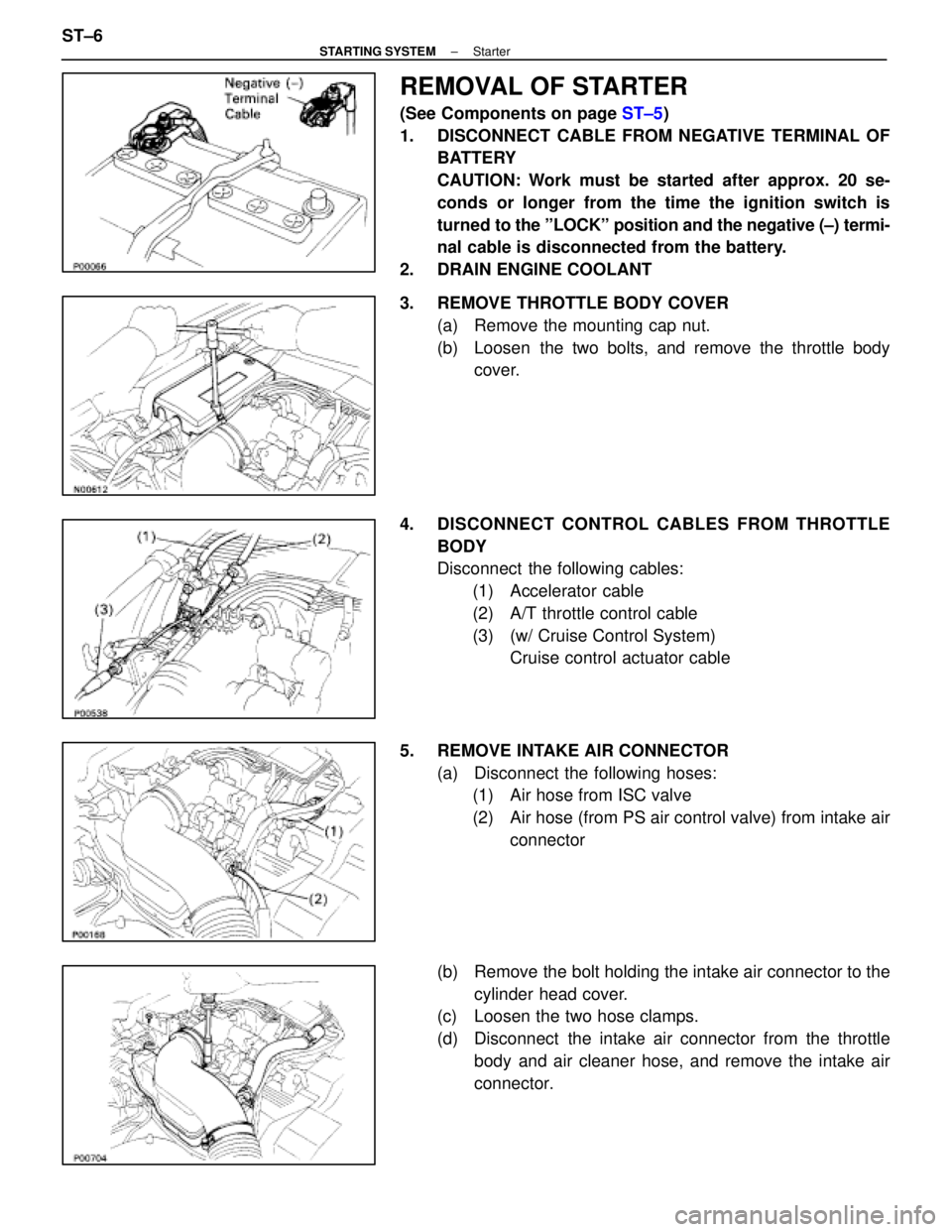
REMOVAL OF STARTER
(See Components on page ST±5)
1. DISCONNECT CABLE FROM NEGATIVE TERMINAL OF BATTERY
CAUTION: Work must be started after approx. 20 se-
conds or longer from the time the ignition switch is
turned to the ºLOCKº position and the negative (±) termi-
nal cable is disconnected from the battery.
2. DRAIN ENGINE COOLANT
3. REMOVE THROTTLE BODY COVER (a) Remove the mounting cap nut.
(b) Loosen the two bolts, and remove the throttle bodycover.
4. DISCONNECT CONTROL CABLES FROM THROTTLE BODY
Disconnect the following cables:(1) Accelerator cable
(2) A/T throttle control cable
(3) (w/ Cruise Control System) Cruise control actuator cable
5. REMOVE INTAKE AIR CONNECTOR (a) Disconnect the following hoses:(1) Air hose from ISC valve
(2) Air hose (from PS air control valve) from intake air
connector
(b) Remove the bolt holding the intake air connector to the cylinder head cover.
(c) Loosen the two hose clamps.
(d) Disconnect the intake air connector from the throttle
body and air cleaner hose, and remove the intake air
connector.
ST±6
±
STARTING SYSTEM Starter
WhereEverybodyKnowsYourName
Page 2582 of 4087
6. REMOVE UPPER HIGH±TENSION CORD COVER(a) Remove the two mounting bolts.
(b) Disconnect the front side claw groove of the cord coverfrom the claw of the lower cover, and remove the cord
cover.
7. REMOVE RH ENGINE WIRE COVER Remove the bolt and engine wire cover.
8. REMOVE LH ENGINE WIRE COVER Remove the two bolts and engine wire cover.
9. REMOVE VSV FOR EVAP SYSTEM Remove the two bolts, and disconnect the VSV from cylinder
head and timing belt cover.
10. REMOVE RH NO.3 TIMING BELT COVER Remove the three bolts and timing belt cover.
±
STARTING SYSTEM StarterST±7
WhereEverybodyKnowsYourName
Page 2587 of 4087
19. DISCONNECT EGR PIPE FROM RH CYLINDER HEADRemove the bolt holding the EGR pipe to the cylinder head,
and disconnect the EGR pipe.
20. DISCONNECT ENGINE WIRE FROM INTAKE MANIFOLD Remove the two bolts, and disconnect the engine wire.
21. DISCONNECT ENGINE WIRE FROM DELIVERY PIPES, REAR WATER BY±PASS JOINT AND RH CYLINDER
HEAD
(a) Remove the four bolts holding the engine wire to thedelivery pipes, and disconnect the engine wire from the
delivery pipe.
(b) Remove the two bolts holding the engine wire to the rear
water by±pass joint, and disconnect the engine wire
from the rear water by±pass joint.
(c) Remove the two bolts holding the engine wire to the rear
side of the RH cylinder head, and disconnect the engine
wire from the RH cylinder head.
(d) Disconnect the two engine wire connectors from the connector bracket on the front side of the LH delivery
pipe.
(e) Disconnect the eight injector connectors.
ST±12
±
STARTING SYSTEM Starter
WhereEverybodyKnowsYourName