Page 2557 of 4087
DESCRIPTION
A fully pressurized, fully filtered lubrication system has been adopted \
for this engine.
OPERATION
LU±2±
LUBRICATION SYSTEM Description, Operation
WhereEverybodyKnowsYourName
Page 2558 of 4087

A pressure feeding lubrication system has been adopted to supply oil to \
the moving parts of this engine. The
lubrication system consists of an oil pan, oil pump, oil filter and other external p\
arts which supply oil to the moving
parts in the engine block. The oil circuit is shown in the illustration at th\
e top of the previous page. Oil from the
oil pan is pumped up by the oil pump. After it passes through the oil fi\
lter, it is fed through the various oil holes
in the crankshaft and cylinder block. After passing through the cylinder b\
lock and performing its lubricating func-
tion, the oil is returned by gravity to the oil pan. A dipstick on the center\
left side of the cylinder block is provided
to check the oil level.
OIL PUMP The oil pump pumps up oil from the oil pan and sends it under pressure to t\
he various parts of the engine.
An oil strainer is mounted in front of the inlet to the oil pump. The oil \
pump itself is a trochoid type pump, inside
of which there is a drive rotor and a driven rotor. When the drive rotor rotates, the driven rotor rotates in the same
direction, and since the axis of the driven rotor shaft is different from the center of the driven rotor, the space
between the two rotors is changed as they rotate. Oil is drawn in when the space\
is wide and is discharged when
the space in narrow.
OIL PRESSURE REGULATOR At high engine speeds, the engine oil supplied by the oil pump exceeds the\
capacity of the engine to utilize
it. For that reason, the oil pressure regulator works to prevent an over\
supply of oil. During normal oil supply, a
coil spring and valve keep the bypass closed, but when too much oil is being \
fed, the pressure become extremely
high, overpowering the force of the spring and opening the valves. This allow\
s the excess oil to flow through
the valve and return to the oil pump inlet.
OIL FILTER The oil filter is a full flow type filter with a built±in paper filter e\
lement. Particles of metal from wear, airborne
dirt, carbon and other impurities can get into the oil during use and co\
uld cause accelerated wear or seizing if
allowed to circulate through the engine. The oil filter, integrated into the oil line, removes these impurities as the
oil passes through it. The filter is mounted outside the engine to simplify\
replacement of the filter element. A relief
valve is also included ahead of the filter element to relieve the high oil pr\
essure in case the filter element be-
comes clogged with impurities. The relief valve opens when the oil pressure o\
verpowers the force of the spring.
Oil passing through the relief valve by±passes the oil filter and flo\
ws directly into the main oil hole in the engine.
±
LUBRICATION SYSTEM PrecautionsLU±3
WhereEverybodyKnowsYourName
Page 2559 of 4087
PREPARATION
SST (SPECIAL SERVICE TOOLS)
RECOMMENDED TOOLS
EQUIPMENT
Part NameNote
Oil pressure gauge
Precision straight edgeOil pump
Torque wrench
LUBRICANT
Item
Capacity
ClassificationItemLitersUS qtslmp. qtsClassification
Engine oilAPI grade SG, Energy±Conserving II
Dry fill606353multigrade. Recommended viscosity is
Drain and refill6.06.35.3gy
as shown, with SAE 5W±30 being the
w/ Oil filter change 4.85.14.2preferred engine oil.
w/o Oil filter change4.54.85.3
g
SSM (SPECIAL SERVICE MATERIALS)
Part NamePart No.Use etc.
Seal packing or equivalent08826±00080Oil pump, Oil pan
Adhesive 1344,
Three bond 1344,08833±00080Oil pressure switch
Loctite 242 or equivalent
LU±4±
LUBRICATION SYSTEM System Circuit, Operation
WhereEverybodyKnowsYourName
Page 2560 of 4087

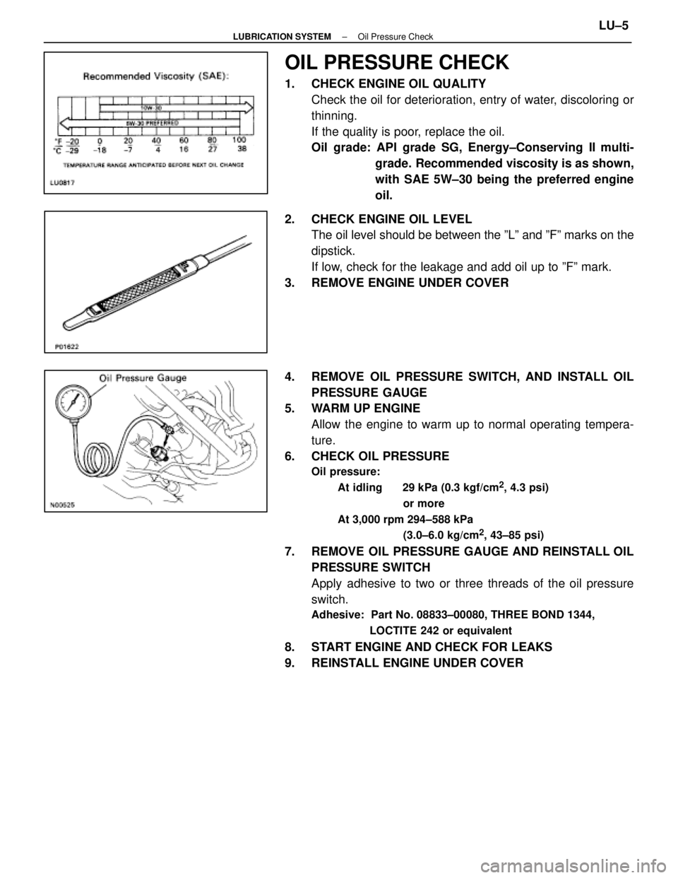
OIL PRESSURE CHECK
1. CHECK ENGINE OIL QUALITYCheck the oil for deterioration, entry of water, discoloring or
thinning.
If the quality is poor, replace the oil.
Oil grade: API grade SG, Energy±Conserving II multi- grade. Recommended viscosity is as shown,
with SAE 5W±30 being the preferred engine
oil.
2. CHECK ENGINE OIL LEVEL The oil level should be between the ºLº and ºFº marks on the
dipstick.
If low, check for the leakage and add oil up to ºFº mark.
3. REMOVE ENGINE UNDER COVER
4. REMOVE OIL PRESSURE SWITCH, AND INSTALL OIL PRESSURE GAUGE
5. WARM UP ENGINE
Allow the engine to warm up to normal operating tempera-
ture.
6. CHECK OIL PRESSURE
Oil pressure:
At idling 29 kPa (0.3 kgf/cm
2, 4.3 psi)
or more
At 3,000 rpm 294±588 kPa (3.0±6.0 kg/cm
2, 43±85 psi)
7. REMOVE OIL PRESSURE GAUGE AND REINSTALL OILPRESSURE SWITCH
Apply adhesive to two or three threads of the oil pressure
switch.
Adhesive: Part No. 08833±00080, THREE BOND 1344,
LOCTITE 242 or equivalent
8. START ENGINE AND CHECK FOR LEAKS
9. REINSTALL ENGINE UNDER COVER
±
LUBRICATION SYSTEM Oil Pressure CheckLU±5
WhereEverybodyKnowsYourName
Page 2561 of 4087

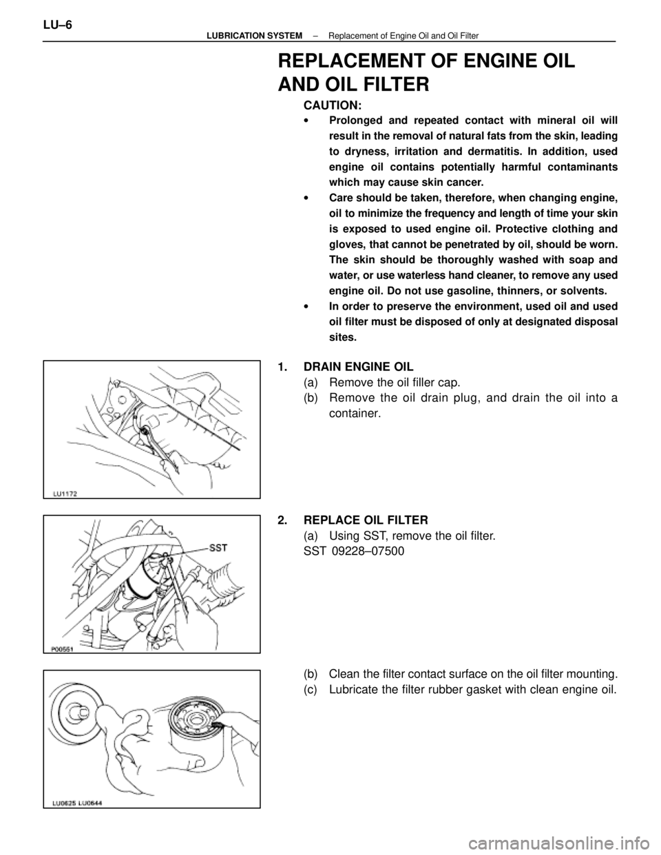
REPLACEMENT OF ENGINE OIL
AND OIL FILTER
CAUTION:
wProlonged and repeated contact with mineral oil will
result in the removal of natural fats from the skin, leading
to dryness, irritation and dermatitis. In addition, used
engine oil contains potentially harmful contaminants
which may cause skin cancer.
w Care should be taken, therefore, when changing engine,
oil to minimize the frequency and length of time your skin
is exposed to used engine oil. Protective clothing and
gloves, that cannot be penetrated by oil, should be worn.
The skin should be thoroughly washed with soap and
water, or use waterless hand cleaner, to remove any used
engine oil. Do not use gasoline, thinners, or solvents.
w In order to preserve the environment, used oil and used
oil filter must be disposed of only at designated disposal
sites.
1. DRAIN ENGINE OIL
(a) Remove the oil filler cap.
(b) Remove the oil drain plug, and drain the oil into acontainer.
2. REPLACE OIL FILTER (a) Using SST, remove the oil filter.
SST 09228±07500
(b) Clean the filter contact surface on the oil filter mounting.
(c) Lubricate the filter rubber gasket with clean engine oil.
LU±6
±
LUBRICATION SYSTEM Replacement of Engine Oil and Oil Filter
WhereEverybodyKnowsYourName
Page 2562 of 4087
(d) Tighten the oil filter by hand until the rubber gasketcontacts the seat of the filter mounting. Then using SST,
give it an additional 3/4 turn to seat the oil filter.
SST 09228±07500
3. FILL WITH ENGINE OIL (a) Clean and install the oil drain plug with a new gasket.
Torque: 25 N Vm (250 kgf Vcm, 18 ft Vlbf)
(b) Fill with new engine oil.
Oil grade: See page LU±5
Capacity: Drain and refillw/ Oil filter change
4.8 liters (5.1 US qts, 4.2 lmp. qts)
w/o Oil filter change 4.5 liters (4.8 US qts, 4.0 lmp.qts)
Dry fill 6.0 liters (6.3 US qts, 5.3 lmp. qts)
(c) Reinstall the oil filler cap.
4. START ENGINE AND CHECK FOR LEAKS
5. RECHECK ENGINE OIL LEVEL (See page LU±5)
±
LUBRICATION SYSTEM Replacement of Engine Oil and Oil FilterLU±7
WhereEverybodyKnowsYourName
Page 2564 of 4087

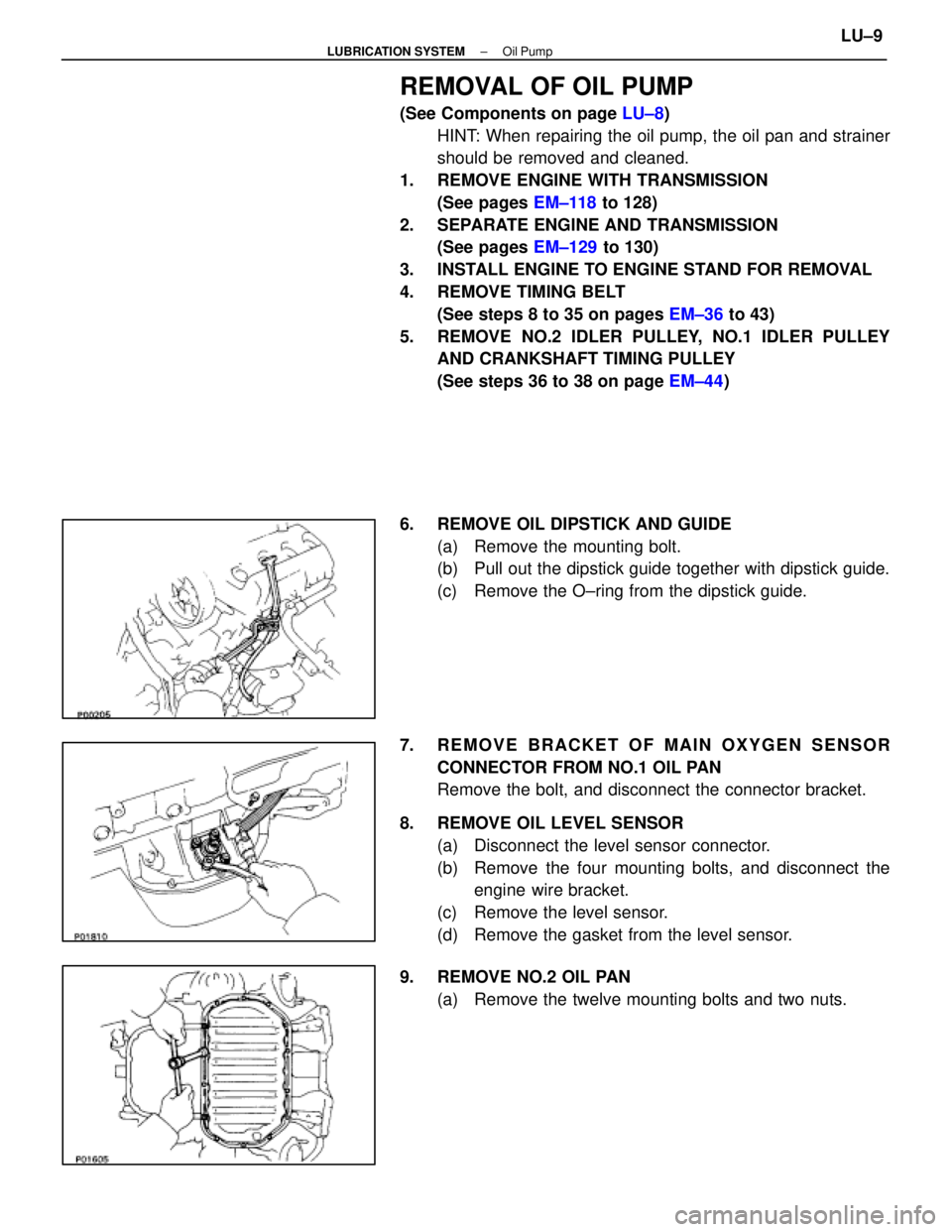
REMOVAL OF OIL PUMP
(See Components on page LU±8)
HINT: When repairing the oil pump, the oil pan and strainer
should be removed and cleaned.
1. REMOVE ENGINE WITH TRANSMISSION (See pages EM±118 to 128)
2. SEPARATE ENGINE AND TRANSMISSION (See pages EM±129 to 130)
3. INSTALL ENGINE TO ENGINE STAND FOR REMOVAL
4. REMOVE TIMING BELT (See steps 8 to 35 on pages EM±36 to 43)
5. REMOVE NO.2 IDLER PULLEY, NO.1 IDLER PULLEY AND CRANKSHAFT TIMING PULLEY
(See steps 36 to 38 on page EM±44)
6. REMOVE OIL DIPSTICK AND GUIDE (a) Remove the mounting bolt.
(b) Pull out the dipstick guide together with dipstick guide.
(c) Remove the O±ring from the dipstick guide.
7. REMOVE BRACKET OF MAIN OXYGEN SENSOR CONNECTOR FROM NO.1 OIL PAN
Remove the bolt, and disconnect the connector bracket.
8. REMOVE OIL LEVEL SENSOR (a) Disconnect the level sensor connector.
(b) Remove the four mounting bolts, and disconnect theengine wire bracket.
(c) Remove the level sensor.
(d) Remove the gasket from the level sensor.
9. REMOVE NO.2 OIL PAN (a) Remove the twelve mounting bolts and two nuts.
±
LUBRICATION SYSTEM Oil PumpLU±9
WhereEverybodyKnowsYourName
Page 2566 of 4087
12. REMOVE OIL STRAINERRemove the two bolts, two nuts, oil strainer and gasket.
13. REMOVE OIL FILTER BRACKET (a) Disconnect the oil pressure switch connector.
(b) Remove the two bo lts, stud bolt, the filter bracket and oil
filter assembly.
(c) Remove the gasket from the filter bracket.
14. REMOVE ENGINE SPEED SENSOR (a) Disconnect the speed sensor connector.
(b) Remove the bolt and speed sensor.
15. REMOVE OIL PUMP (a) Remove the eight mounting bolts.
(b) Remove the oil pump by prying the portions between the
cylinder block and oil pump with a screwdriver.
NOTICE: Be careful not to damage the contact surfaces
of the cylinder block and oil pump.
(c) Remove the O±ring from the cylinder block.
±
LUBRICATION SYSTEM Oil PumpLU±11
WhereEverybodyKnowsYourName