Page 2683 of 4087
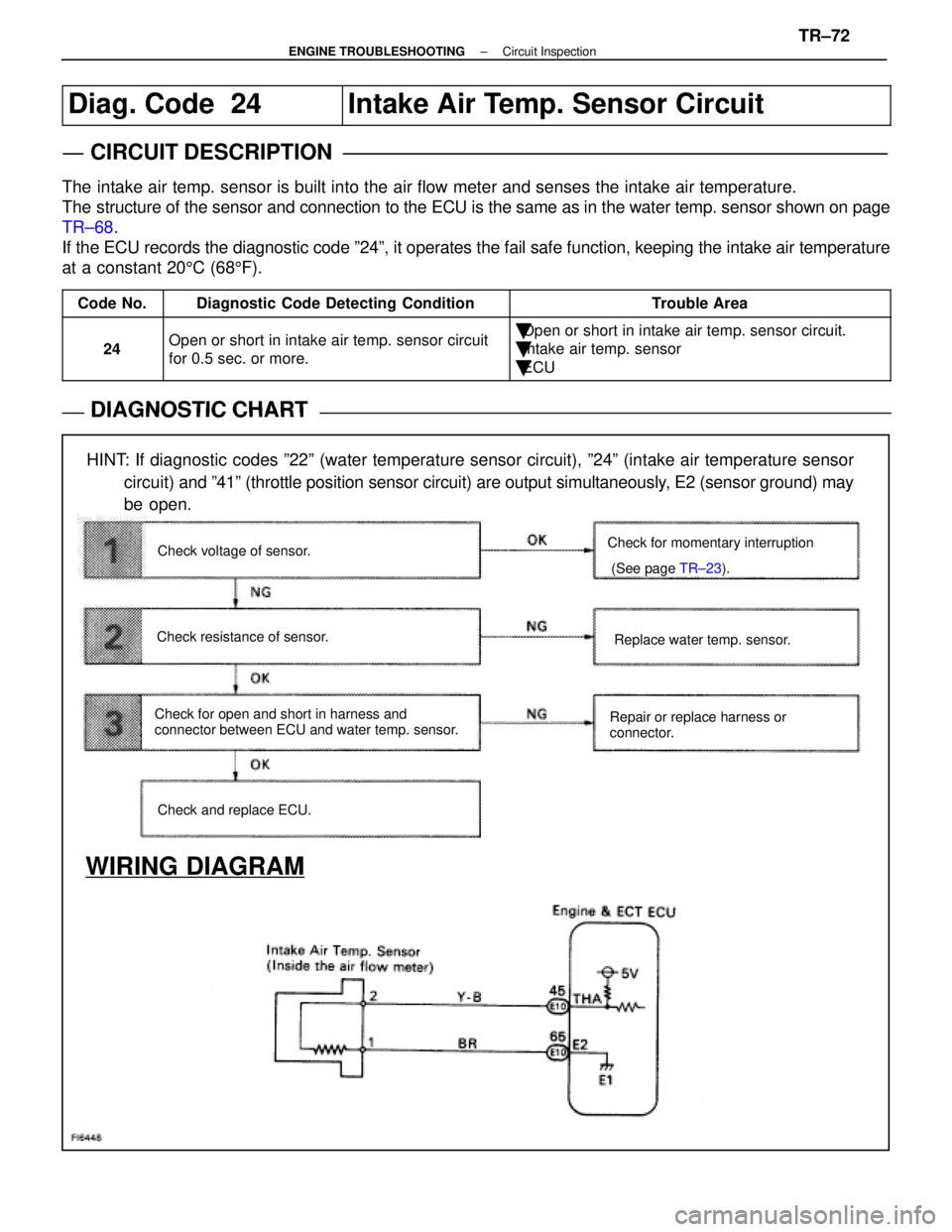
Diag. Code 24Intake Air Temp. Sensor Circuit
CIRCUIT DESCRIPTION
The intake air temp. sensor is built into the air flow meter and senses the\
intake air temperature.
The structure of the sensor and connection to the ECU is the same as in the\
water temp. sensor shown on page
TR±68.
If the ECU records the diagnostic code º24º, it operates the fail \
safe function, keeping the intake air temperature
at a constant 20 5C (68 5F).
Code No.Diagnostic Code Detecting ConditionTrouble Area
24Open or short in intake air temp. sensor circuit
for 0.5 sec. or more.�Open or short in intake air temp. sensor circuit.
�Intake air temp. sensor
�ECU
DIAGNOSTIC CHARTDIAGNOSTIC CHART
HINT: If diagnostic codes º22º (water temperature sensor circuit), º\
24º (intake air temperature sensor
circuit) and º41º (throttle position sensor circuit) are output simultaneousl\
y, E2 (sensor ground) may
be open.
WIRING DIAGRAM
Check and replace ECU. Replace water temp. sensor.
Check for momentary interruption
(See page
TR±23).
Repair or replace harness or
connector.
Check voltage of sensor.
Check resistance of sensor.
Check for open and short in harness and
connector between ECU and water temp. sensor.
±
ENGINE TROUBLESHOOTING Circuit InspectionTR±72
WhereEverybodyKnowsYourName
Page 2705 of 4087
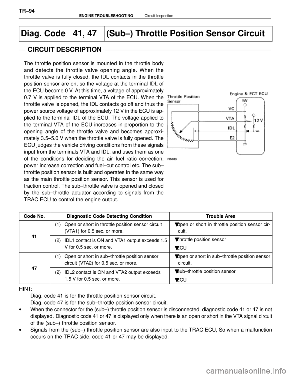
Diag. Code 41, 47(Sub±) Throttle Position Sensor Circuit
CIRCUIT DESCRIPTION
The throttle position sensor is mounted in the throttle body
and detects the throttle valve opening angle. When the
throttle valve is fully closed, the IDL contacts in the throttle
position sensor are on, so the voltage at the terminal IDL of
the ECU become 0 V. At this time, a voltage of approximately
0.7 V is applied to the terminal VTA of the ECU. When the
throttle valve is opened, the IDL contacts go off and thus the
power source voltage of approximately 12 V in the ECU is ap-
plied to the terminal IDL of the ECU. The voltage applied to
the terminal VTA of the ECU increases in proportion to the
opening angle of the throttle valve and becomes approxi-
mately 3.5±5.0 V when the throttle valve is fully opened. The
ECU judges the vehicle driving conditions from these signals
input from the terminals VTA and IDL, and uses them as one
of the conditions for deciding the air±fuel ratio correction,
power increase correction and fuel±cut control etc. The sub±
throttle position sensor is built and operates in the same way
as the main throttle position sensor. This sensor is used for
traction control. The sub±throttle valve is opened and closed
by the sub±throttle actuator according to signals from the
TRAC ECU to control the engine output.
Code No.Diagnostic Code Detecting ConditionTrouble Area
41
(1) Open or short in throttle position sensor circuit(VTA1) for 0.5 sec. or more.�Open or short in throttle position sensor cir-
cuit.
41(2) IDL1 contact is ON and VTA1 output exceeds 1.5 V for 0.5 sec. or more.�Throttle position sensor
� ECU
47
(1) Open or short in sub±throttle position sensor
circuit (VTA2) for 0.5 sec. or more.�Open or short in sub±throttle position sensor
circuit.
47(2) IDL2 contact is ON and VTA2 output exceeds 1.5 V for 0.5 sec. or more.�Sub±throttle position sensor
� ECU
HINT:
Diag. code 41 is for the throttle position sensor circuit.
Diag. code 47 is for the sub±throttle position sensor circuit.
w When the connector for the (sub±) throttle position sensor is disconnec\
ted, diagnostic code 41 or 47 is not
displayed. Diagnostic code 41 or 47 is displayed only when there is an open or short in the VTA signal circuit
of the (sub±) throttle position sensor.
w Signals from the (sub±) throttle position sensor are also input to the TRAC ECU, So when a malfu\
nction
occurs on the TRAC side, code 41 or 47 may be displayed.
TR±94
±
ENGINE TROUBLESHOOTING Circuit Inspection
WhereEverybodyKnowsYourName
Page 2706 of 4087
DIAGNOSTIC CHART
DIAGNOSTIC
CHART
HINT:
wIf diag. code 41 is displayed, check throttle position sensor circuit; if d\
iag. code 47 is displayed,
check sub±throttle position sensor circuit.
w If diag. codes º22º (water temperature sensor circuit), º24º\
(intake air temperature sensor circuit)
and º41º (throttle position sensor circuit) are output simultaneous\
ly, E2 (sensor ground) may be
open.
WIRING DIAGRAM
Check and replace ECU. Adjust or replace throttle position
sensor.
Check for momentary interruption
(See page
TR±23).
Repair or replace harness or
connector.
Check voltage of throttle position sensor.
Check operation for throttle position sensor.
Check for open and short in harness and
connector between throttle position sensor and ECU.
±
ENGINE TROUBLESHOOTING Circuit InspectionTR±95
WhereEverybodyKnowsYourName
Page 2707 of 4087
NGOK
INSPECTION PROCEDURE
HINT:
wIf diag. code 41 is displayed, check throttle position sensor circuit. If \
diag. code 47 is displayed, check
sub±throttle position sensor circuit.
w If diag. codes º22º (water temperature sensor circuit), º24º\
(intake air temperature sensor circuit) and º41º
(throttle position sensor circuit) are output simultaneously, E2 (sensor ground) may be open.
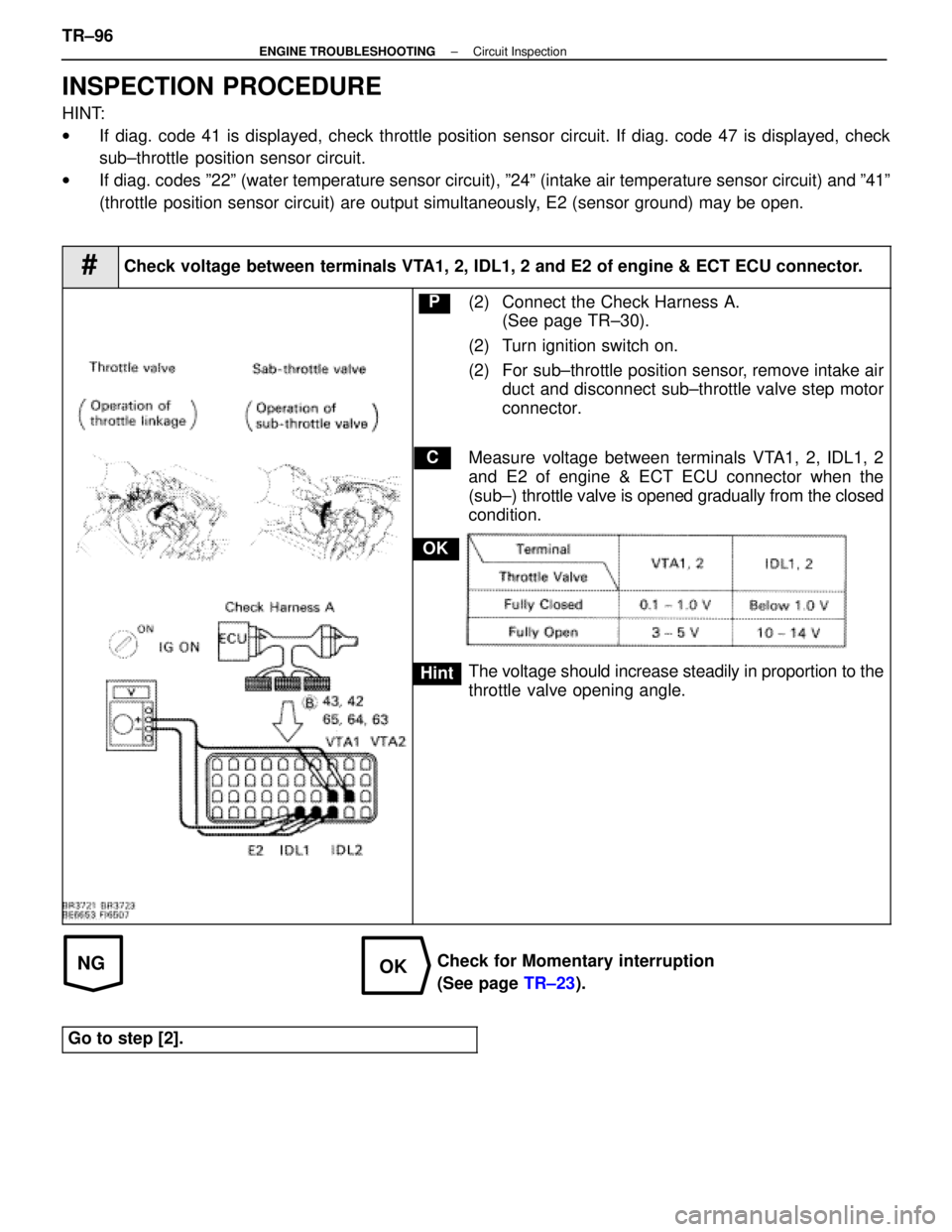
#Check voltage between terminals VTA1, 2, IDL1, 2 and E2 of engine & ECT ECU connector.
C
OK
Hint
P(2) Connect the Check Harness A.
(See page TR±30).
(2) Turn ignition switch on.
(2) For sub±throttle position sensor, remove intake air duct and disconnect sub±throttle valve step motor
connector.
Measure voltage between terminals VTA1, 2, IDL1, 2
and E2 of engine & ECT ECU connector when the
(sub±) throttle valve is opened gradually from the closed
condition.
The voltage should increase steadily in proportion to the
throttle valve opening angle.
Check for Momentary interruption
(See page TR±23).
Go to step [2].
TR±96±
ENGINE TROUBLESHOOTING Circuit Inspection
WhereEverybodyKnowsYourName
Page 2708 of 4087
OKNG
OKNG
2Check (sub±) throttle position sensor.
C
OK
Hint
P(2) Remove intake air duct.
(2) Disconnect (sub±) throttle position sensor connec-tor.
Measure resistance between terminals 3, 2, and 1 of
(sub±) throttle position sensor connector when the
throttle valve is opened gradually from the closed condi-
tion.
Resistance between terminals 3 and 1 should increase
gradually in accordance with the throttle valve opening
angle.
Adjust or replace (sub±) throttle position sensor
(See page FI±73).
3Check for open and short in harness and connector between engine & ECT E\
CU and
(sub±) throttle position sensor (See page IN±27).
Repair or replace harness or connector.
Check and replace engine & ECT ECU.
±
ENGINE TROUBLESHOOTING Circuit InspectionTR±97
WhereEverybodyKnowsYourName
Page 2729 of 4087
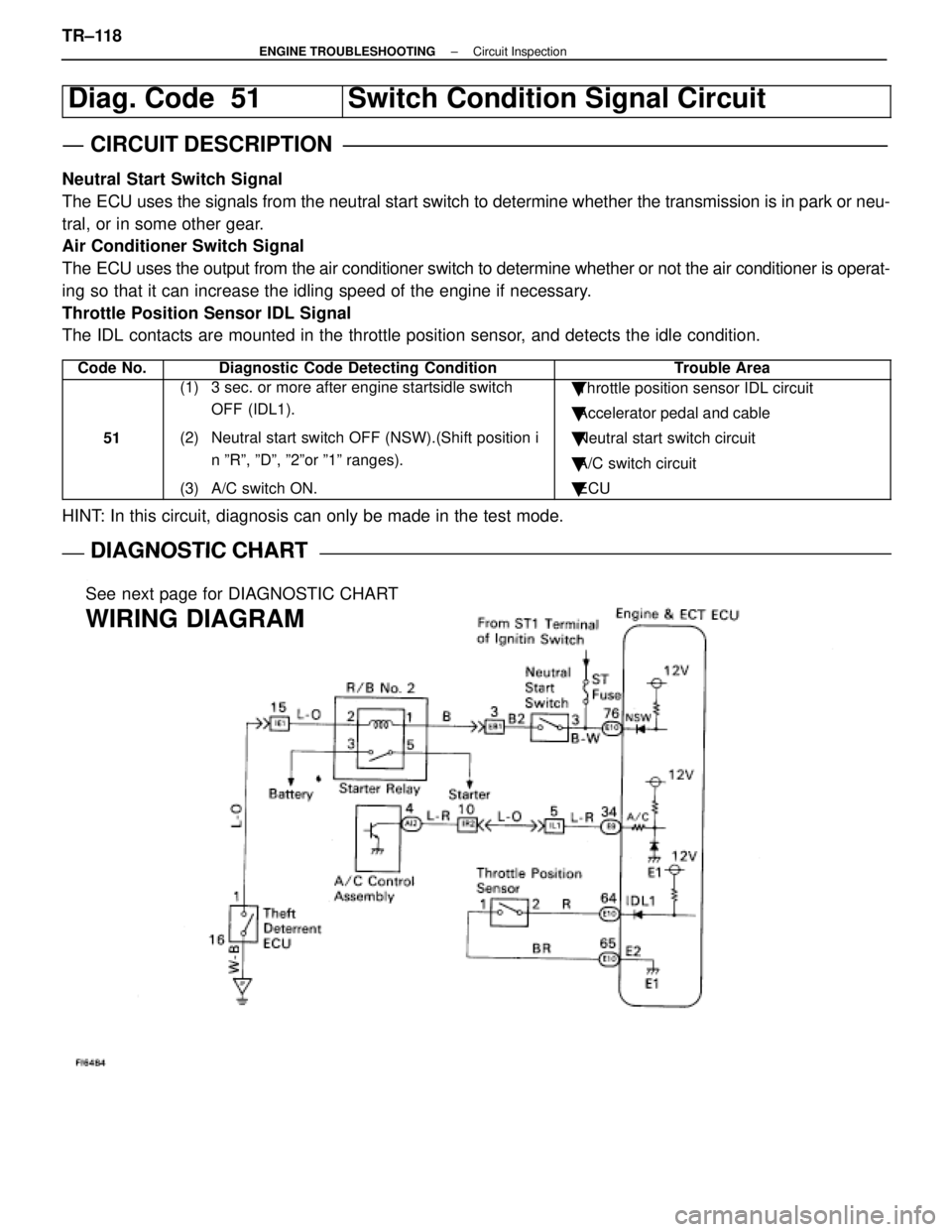
Diag. Code 51Switch Condition Signal Circuit
CIRCUIT DESCRIPTION
Neutral Start Switch Signal
The ECU uses the signals from the neutral start switch to determine whether\
the transmission is in park or neu-
tral, or in some other gear.
Air Conditioner Switch Signal
The ECU uses the output from the air conditioner switch to determine whethe\
r or not the air conditioner is operat-
ing so that it can increase the idling speed of the engine if necessary.
Throttle Position Sensor IDL Signal
The IDL contacts are mounted in the throttle position sensor, and detects the idle condition.
Code No.Diagnostic Code Detecting ConditionTrouble Area
51
(1) 3 sec. or more after engine startsidle switch OFF (IDL1).
(2) Neutral start switch OFF (NSW).(Shift position i n ºRº, ºDº, º2ºor º1º ranges).
(3) A/C switch ON.� Throttle position sensor IDL circuit
� Accelerator pedal and cable
� Neutral start switch circuit
� A/C switch circuit
� ECU
HINT: In this circuit, diagnosis can only be made in the test mode.
DIAGNOSTIC CHARTDIAGNOSTIC CHART
See next page for DIAGNOSTIC CHART
WIRING DIAGRAM
TR±118±
ENGINE TROUBLESHOOTING Circuit Inspection
WhereEverybodyKnowsYourName
Page 2730 of 4087
DIAGNOSTIC CHART
DIAGNOSTIC
CHART
NG (NSW)
Check for input signal.
Proceed to next circuit inspection shown
on maxtrix chart (See page TR±35).
Check resistance of throttle
position sensor.
Check input circuit of A/C.
Check and repair harness or connector
between sensor and ECU.
Check for open and short in harness
and connector beteen A/C control assy.
and ECU.
Repair or replace harness or
connector.
Check and replace A/C control
assembly.
Adjust or replace throttle position
sensor (See page FI-73).
See page TR±122.
Check and replace ECU.
±
ENGINE TROUBLESHOOTING Circuit InspectionTR±119
WhereEverybodyKnowsYourName
Page 2731 of 4087
OKNG
OKNG
INSPECTION PROCEDURE
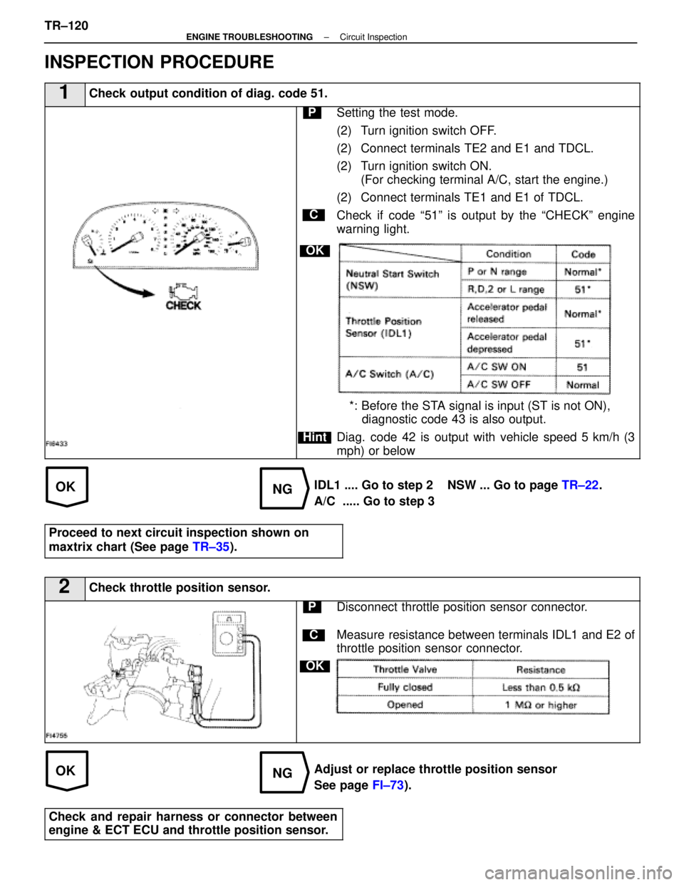
1Check output condition of diag. code 51.
C
OK
Hint
PSetting the test mode.
(2) Turn ignition switch OFF.
(2) Connect terminals TE2 and E1 and TDCL.
(2) Turn ignition switch ON.(For checking terminal A/C, start the engine.)
(2) Connect terminals TE1 and E1 of TDCL.
Check if code ª51º is output by the ªCHECKº engine
warning light.
*: Before the STA signal is input (ST is not ON), diagnostic code 43 is also output.
Diag. code 42 is output with vehicle speed 5 km/h (3
mph) or below
IDL1 .... Go to step 2 NSW ... Go to page TR±22.
A/C ..... Go to step 3
Proceed to next circuit inspection shown on
maxtrix chart (See page TR±35).
2Check throttle position sensor.
C
OK
PDisconnect throttle position sensor connector.
Measure resistance between terminals IDL1 and E2 of
throttle position sensor connector.
Adjust or replace throttle position sensor
See page FI±73).
Check and repair harness or connector between
engine & ECT ECU and throttle position sensor.
TR±120±
ENGINE TROUBLESHOOTING Circuit Inspection
WhereEverybodyKnowsYourName