Page 2514 of 4087

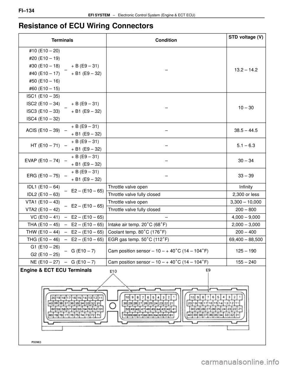
Resistance of ECU Wiring Connectors
TerminalsConditionSTD voltage (V)
#10 (E10 ± 20)
#20 (E10 ± 19)
#30 (E10 ± 18)+ B (E9 ± 31)13 2 14 2#40 (E10 ± 17)±+ B1 (E9 ± 32) ±13.2 ± 14.2
#50 (E10 ± 16)
#60 (E10 ± 15)
ISC1 (E10 ± 35)
ISC2 (E10 ± 34)+ B (E9 ± 31)10 30ISC3 (E10 ± 33)±
+ B1 (E9 ± 32) ±10 ± 30
ISC4 (E10 ± 32)
ACIS (E10 39)+ B (E9 ± 31)38 5 44 5ACIS (E10 ± 39)±
+ B1 (E9 ± 32) ±38.5 ± 44.5
HT (E10 71)+ B (E9 ± 31)51 63HT (E10 ± 71)±
+ B1 (E9 ± 32) ±5.1 ± 6.3
EVAP (E10 74)+ B (E9 ± 31)30 34EVAP (E10 ± 74)±
+ B1 (E9 ± 32) ±30 ± 34
ERG (E10 75)+ B (E9 ± 31)33 39ERG (E10 ± 75)±
+ B1 (E9 ± 32) ±33 ± 39
IDL1 (E10 ± 64)E2 (E10 65)Throttle valve openInfinity
IDL2 (E10 ± 63)± E2 ± (E10 ± 65)Throttle valve fully closed2,300 or less
VTA1 (E10 ± 43)E2 (E10 65)Throttle valve open3,300 ± 10,000
VTA2 (E10 ± 42)± E2 ± (E10 ± 65)Throttle valve fully closed200 ± 800
VC (E10 ± 41)±E2 ± (E10 ± 65)±4,000 ± 9,000
THA (E10 ± 45)±E2 ± (E10 ± 65)Intake air temp. 20
°C (68 °F)2,000 ± 3,000
THW (E10 ± 44)±E2 ± (E10 ± 65)Coolant temp. 80 °C (176 °F)200 ± 400
THG (E10 ± 46)±E2 ± (E10 ± 65)EGR gas temp. 50 °C (112 °F)69,400 ± 88,500
G1 (E10 ± 26)G (E10 7)Camposition sensor 10 + 40°C (14 104°F)125 190G2 (E10 ± 25)±G (E10 ± 7)Cam position sensor ± 10 ± + 40°C (14 ± 104°F)125 ± 190
NE (E10 ± 27)±G (E10 ± 7)Cam position sensor ± 10 ± + 40 °C (14 ± 104 °F)155 ± 240
Engine & ECT ECU Terminals
FI±134EFI SYSTEM ± Electronic Control System (Engine & ECT ECU)
WhereEverybodyKnowsYourName
Page 2517 of 4087

SERVICE SPECIFICATIONS
SERVICE DATA
Fuel pumpResistance0.2 ± 3.0 �
Cold start
injectorResistance
Fuel leakage2 ± 4 �
One drop or less per minute
Fuel pressure
regulatorFuel pressureat no vacuum265 ± 304 kPa
(2.7 ± 3.1 kgf/cm2, 38 ± 44 psi)
InjectorResistance
Injection volume
Difference between each cylinder
Fuel leakage13.4 ± 14.2 �
55 ± 70 cc (3.4 ± 4.3 cu in.) per 15 sec.
10 cc (0.6 cu in.) or less
One drop or less per minute
Air flow meterResistance (THA ± E2)at±20 °C (±4 °F)
at 0 °C (32 °F)
at 20 °C (68 °F)
at 40 °C (104 °F)
at 60 °C (140 °F)
at 80 °C (176 °F)10 ± 20 k �
4 ± 7 k �
2 ± 7 k �
0.9 ± 1.3 k �
0.4 ± 0.7 k �
0.2 ± 0.4 k �
Throttle bodyThrottle body fully closed angle6°
Throttle
positionClearance between
stop screw and leverBetween terminalsResistance
sensor
(main)0 mm
0.40 mm
0.65 mm0 in.
0.016 in.
0.026 in.VTA1 ± E2 IDL1 ± E2
IDL1 ± E2
VTA1 E2
0.2 ± 0.8 k �
2.3 k � or less
Infinity
33 100k �Throttle valve fully opened position
±VTA1 ± E2VC ± E2
y
3.3 ± 10.0 k �
4.0 ± 9.0 k �
Sub±throttle
positionClearance between
stop screw and leverBetween terminalsResistance
sensor
(w/ TRAC)0 mm
0.30 mm
0.50 mm0 in.
0.012 in.
0.020 in.VTA2 ± E2 IDL2 ± E2
IDL2 ± E2
VTA2 E2
0.2 ± 0.8 k �
2.3 k � or less
Infinity
33 100k �Throttle valve fully opened position
±VTA2 ± E2VC ± E2
y
3.3 ± 10.0 k �
4.0 ± 9.0 k �
Sub±throttle
actuator
(w/ TRAC)Resistance (ACM ± A and A, BCM ± B and B)0.5 ± 1.0 �
ISC valveResistance (B1 ± S1 and S3, B2 ± S2 and S4)10 ± 30 �
Cold start
injector time
switchResistance STA ± STJ below 15 °C (59 °F)
above 30 °C (86 °F)
STA ± Ground25 ± 45 �
65 ± 85
25 ± 85 �
VSV for fuel
pressure
controlResistance37 ± 44 �
FI±137 ± Service SpecificationsEFI SYSTEM
WhereEverybodyKnowsYourName
Page 2521 of 4087
SERVICE DATA (Cont'd)
ECU (cont'd)Resistance of wiring connector side (cont'd)
TerminalsConditionSTD voltage (�)
±
HTR1
HTR2
HTL1
HTL2 +B
+B1±5.1 ± 6.3
±
PA G +B
+B1±30 ± 34
±IDL1 +BThrottle valve fully openInfinity
±IDL1
IDL2
+B
+B1Throttle valve fully closed2,300 or less
±VTA1E2
Throttle valve fully open3,300 ± 10,000
±VTA1
VTA2E2
Throttle valve fully closed200 ± 800
VC ± E2±4,000 ± 9,000
THS ± E2Intake air temp, 20
°C (68 °F)2,000 ± 3,000
THW ± E2Coolant temp. 80 °C (176 °F)200 ± 400
THG ± E2EGR gas temp. 50 °C (112 °F)69,400 ± 88,500
G1
G2 G1 (±)
G2 (±)
±Cam position sensor ± 10 ± +40
°C (14 ± 104 °F)835 ± 1,350
NE ± NE (±)engine speed sensor ± 10 ± +40 °C (14 ± 104 °F)835 ± 1,350
Fuel cut rpmw/ Vehicle speed 0 km/h and coolant temp. 80 °C (176 °F)
Fuel cut rpm
Fuel return rpm
1,800 rpm
1,400 rpm
FI±141EFI SYSTEM ± Service Specifications
WhereEverybodyKnowsYourName
Page 2551 of 4087
(c) Check the ignition timing.
Ignition timing: 8±125 BTDC @ idle
(Transmission in neutral range)
If the ignition timing is not as specified, check that following
conditions are normal: w Throttle valve fully closed
w Continuity between terminals IDL1 and E2 of the
throttle position sensor (See page FI±73)
w Valve timing (See page EM±51)
(e) Remove the SST from the check connector.
SST 09843±18020
17. DISCONNECT TACHOMETER AND TIMING LIGHT FROM ENGINE
18. INSTALL UPPER HIGH±TENSION CORD COVER (See step 10 on pages IG±18 and 19)
±
IGNITION SYSTEM DistributorIG±29
WhereEverybodyKnowsYourName
Page 2581 of 4087

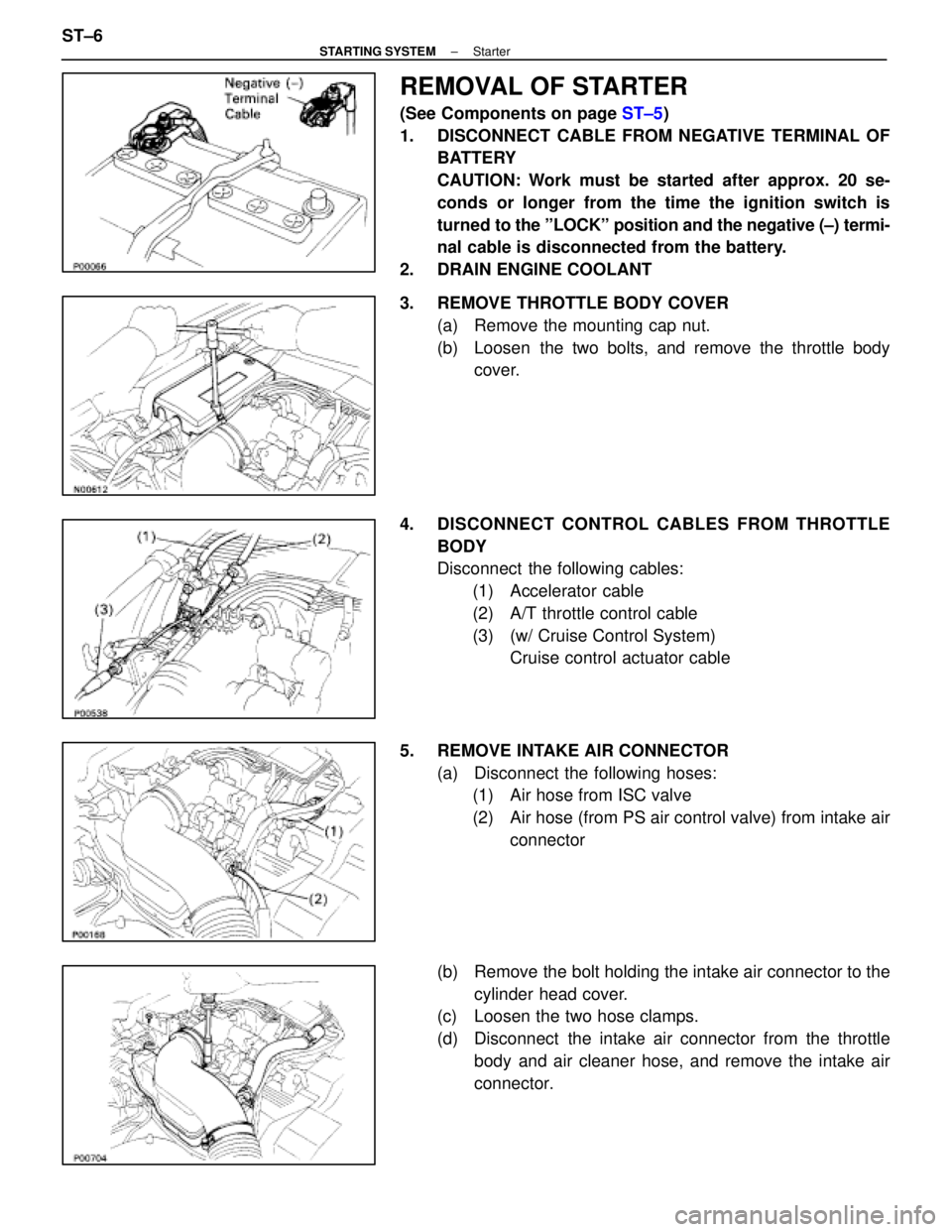
REMOVAL OF STARTER
(See Components on page ST±5)
1. DISCONNECT CABLE FROM NEGATIVE TERMINAL OF BATTERY
CAUTION: Work must be started after approx. 20 se-
conds or longer from the time the ignition switch is
turned to the ºLOCKº position and the negative (±) termi-
nal cable is disconnected from the battery.
2. DRAIN ENGINE COOLANT
3. REMOVE THROTTLE BODY COVER (a) Remove the mounting cap nut.
(b) Loosen the two bolts, and remove the throttle bodycover.
4. DISCONNECT CONTROL CABLES FROM THROTTLE BODY
Disconnect the following cables:(1) Accelerator cable
(2) A/T throttle control cable
(3) (w/ Cruise Control System) Cruise control actuator cable
5. REMOVE INTAKE AIR CONNECTOR (a) Disconnect the following hoses:(1) Air hose from ISC valve
(2) Air hose (from PS air control valve) from intake air
connector
(b) Remove the bolt holding the intake air connector to the cylinder head cover.
(c) Loosen the two hose clamps.
(d) Disconnect the intake air connector from the throttle
body and air cleaner hose, and remove the intake air
connector.
ST±6
±
STARTING SYSTEM Starter
WhereEverybodyKnowsYourName
Page 2583 of 4087
11. REMOVE LH NO.3 TIMING BELT COVER(a) Remove the four mounting bolts.
(b) Disconnect the cord grommet from the timing belt cover,
and remove the timing belt cover.
(c) Remove the cord grommet from the high±tension cord.
12. REMOVE LOWER HIGH±TENSION CORD COVER (a) Disconnect the high±tension cord from the RH ignitioncoil.
(b) D i s c onnect the high±tension cords from the
high±tension cord cover.
(c) Remove the bolt and cord cover.
13. REMOVE THROTTLE BODY (a) Disconnect the following connectors:(1) Throttle position sensor connector
(2) (w/ TRAC)
Sub±throttle position sensor connector
(3) (w/ TRAC) Sub±throttle actuator connector
(b) Disconnect the following hoses: (1) Heat water hose from heater water valve
ST±8
±
STARTING SYSTEM Starter
WhereEverybodyKnowsYourName
Page 2606 of 4087
(d) Connect the following hoses:(1) Water by±pass hose to the ISC valve
(2) (USA Spec.) Vacuum hose to throttle body
(3) (Exc. USA Spec.) Three vacuum hoses to throttle body
(4) Heater water hose to heater water valve
(e) Connect the following connectors: (1) Throttle position sensor connector
(2) (w/ TRAC) Sub±throttle position sensor connector
(3) (w/ TRAC) Sub±throttle actuator connector
16. INSTALL LOWER HIGH±TENSION CORD COVER (a) Connect the end portions of the high±tension cord to the
cord clamps
(b) Install the high±tension cord cover with the bolt.
±
STARTING SYSTEM StarterST±31
WhereEverybodyKnowsYourName
Page 2608 of 4087

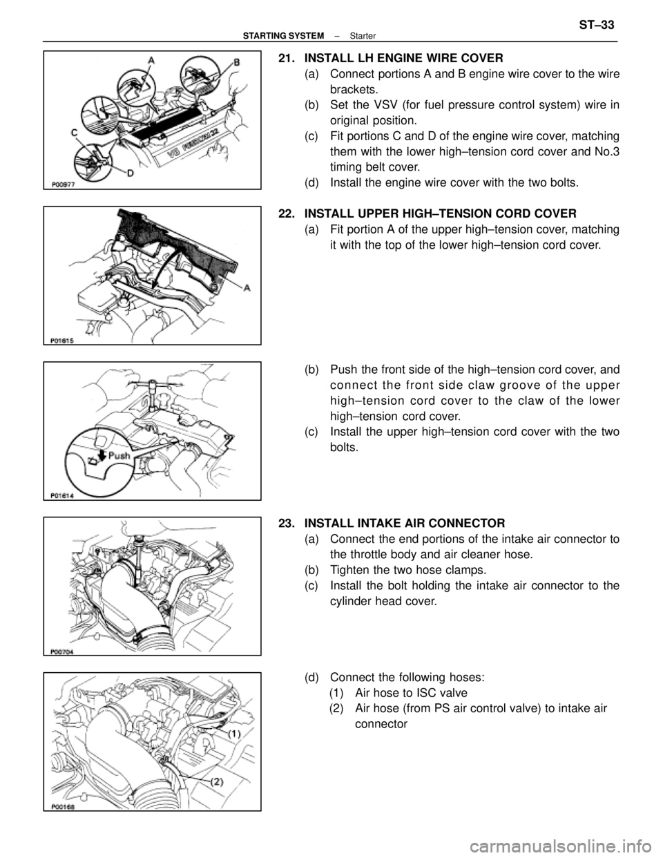
21. INSTALL LH ENGINE WIRE COVER(a) Connect portions A and B engine wire cover to the wirebrackets.
(b) Set the VSV (for fuel pressure control system) wire in
original position.
(c) Fit portions C and D of the engine wire cover, matching them with the lower high±tension cord cover and No.3
timing belt cover.
(d) Install the engine wire cover with the two bolts.
22. INSTALL UPPER HIGH±TENSION CORD COVER (a) Fit portion A of the upper high±tension cover, matchingit with the top of the lower high±tension cord cover.
(b) Push the front side of the high±tension cord cover, and connect the front side claw groove of the upper
high±tension cord cover to the claw of the lower
high±tension cord cover.
(c) Install the upper high±tension cord cover with the two
bolts.
23. INSTALL INTAKE AIR CONNECTOR (a) Connect the end portions of the intake air connector tothe throttle body and air cleaner hose.
(b) Tighten the two hose clamps.
(c) Install the bolt holding the intake air connector to the cylinder head cover.
(d) Connect the following hoses: (1) Air hose to ISC valve
(2) Air hose (from PS air control valve) to intake air connector
±
STARTING SYSTEM StarterST±33
WhereEverybodyKnowsYourName