Page 2226 of 4087
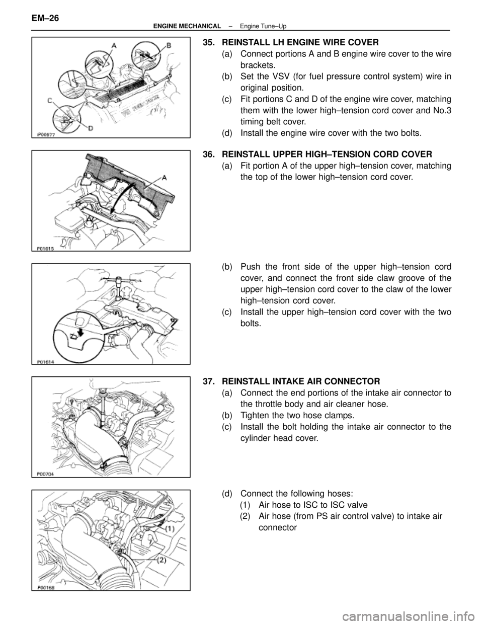
35. REINSTALL LH ENGINE WIRE COVER(a) Connect portions A and B engine wire cover to the wirebrackets.
(b) Set the VSV (for fuel pressure control system) wire in
original position.
(c) Fit portions C and D of the engine wire cover, matching them with the lower high±tension cord cover and No.3
timing belt cover.
(d) Install the engine wire cover with the two bolts.
36. REINSTALL UPPER HIGH±TENSION CORD COVER (a) Fit portion A of the upper high±tension cover, matchingthe top of the lower high±tension cord cover.
(b) Push the front side of the upper high±tension cord cover, and connect the front side claw groove of the
upper high±tension cord cover to the claw of the lower
high±tension cord cover.
(c) Install the upper high±tension cord cover with the two bolts.
37. REINSTALL INTAKE AIR CONNECTOR (a) Connect the end portions of the intake air connector tothe throttle body and air cleaner hose.
(b) Tighten the two hose clamps.
(c) Install the bolt holding the intake air connector to the cylinder head cover.
(d) Connect the following hoses: (1) Air hose to ISC to ISC valve
(2) Air hose (from PS air control valve) to intake air connector
EM±26
±
ENGINE MECHANICAL Engine Tune±Up
WhereEverybodyKnowsYourName
Page 2229 of 4087
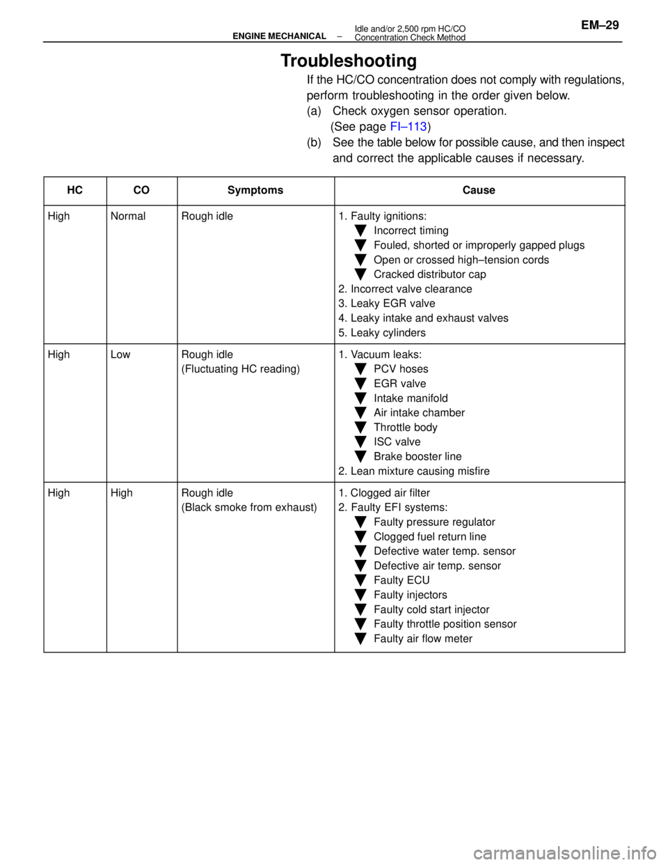
Troubleshooting
If the HC/CO concentration does not comply with regulations,
perform troubleshooting in the order given below.
(a) Check oxygen sensor operation.(See page FI±113)
(b) See the table below for possible cause, and then inspect
and correct the applicable causes if necessary.
����� �
����
�����HC����� �
����
�����CO���������� �
���������
����������Symptoms������������������\
� �
������������������
������������������\
�Cause
����� �����High����� �����Normal���������� ����������Rough idle������������������\
� ������������������\
�1. Faulty ignitions:
����� ���������� ��������������� ����������������������������\
� ������������������\
��Incorrect timing
����� ���������� ��������������� ����������������������������\
� ������������������\
��Fouled, shorted or improperly gapped plugs
����� ���������� ��������������� ����������������������������\
� ������������������\
��Open or crossed high±tension cords
Ckddiib��������������������������������������\
��Cracked distributor cap
Ill����� ���������� ��������������� ����������������������������\
� ������������������\
�2. Incorrect valve clearance
3 L k EGR l����� ���������� ��������������� ����������������������������\
� ������������������\
�3. Leaky EGR valve
4L k i k d h l����� ���������� ��������������� ����������������������������\
� ������������������\
�4. Leaky intake and exhaust valves
L k li d����� ���������� ��������������� ����������������������������\
� ������������������\
�5. Leaky cylinders
����� �����High����� �����Low���������� ����������Rough idle������������������\
� ������������������\
�1. Vacuum leaks:
����� ���������� ��������������� ����������(Fluctuating HC reading)������������������\
� ������������������\
��PCV hoses
����� ���������� ��������������� ����������������������������\
� ������������������\
��EGR valve
����� ���������� ��������������� ����������������������������\
� ������������������\
��Intake manifold
Ai i k h b����� ���������� ��������������� ����������������������������\
� ������������������\
��Air intake chamber
Th l b d����� ���������� ��������������� ����������������������������\
� ������������������\
��Throttle body
ISC l��������������������������������������\
��ISC valve
Bkb li����� ���������� ��������������� ����������������������������\
� ������������������\
��Brake booster line
2L i i ifi����� ���������� ��������������� ����������������������������\
� ������������������\
�2. Lean mixture causing misfire
����� �����High����� �����High���������� ����������Rough idle������������������\
� ������������������\
�1. Clogged air filter����� �����g����� �����g���������� ����������g
(Black smoke from exhaust)������������������\
� ������������������\
�gg
2. Faulty EFI systems:����� ���������� ��������������� ����������()������������������\
� ������������������\
�yy
�Faulty pressure regulator
����� ���������� ��������������� ����������������������������\
� ������������������\
�
yg
�Clogged fuel return line
����� ���������� ��������������� ����������������������������\
� ������������������\
�
gg
�Defective water temp. sensor
����� ���������� ��������������� ����������������������������\
� ������������������\
��Defective air temp. sensor
����� ���������� ��������������� ����������������������������\
� ������������������\
��Faulty ECU
����� ���������� ��������������� ����������������������������\
� ������������������\
�
y
�Faulty injectors
��������������������������������������\
�
yj
�Faulty cold start injector����� ���������� ��������������� ����������������������������\
� ������������������\
�yj
�Faulty throttle position sensor����� ���������� ��������������� ����������������������������\
� ������������������\
��Faulty air flow meter
±
ENGINE MECHANICAL Idle and/or 2,500 rpm HC/CO
Concentration Check MethodEM±29
WhereEverybodyKnowsYourName
Page 2264 of 4087
(b) Remove the two bolts, two nuts, adaptor and gasket.
(c) (USA Spec. only)Disconnect the EGR gas temperature sensor connec-
tor.
14. REMOVE ISC VALVE (a) Disconnect the ISC valve connector.
(b) Disconnect the water by±pass hose from the ISC valve.
(c) Remove the two nuts, ISC valve and gasket.
15. DISCONNECT HEATER WATER VALVE FROM BODY (a) Disconnect the VSV connector.
(b) Remove the bolt holding the engine wire clamp to thewater valve bracket.
(c) Remove the two bolts, and disconnect the water valve and bracket assembly.
16. REMOVE THROTTLE BODY (a) Disconnect the following connectors:(1) Throttle position sensor connector
(2) (w/ TRAC)
Sub±throttle position sensor connector
(3) (w/ TRAC) Sub±throttle actuator connector
EM±64
±
ENGINE MECHANICAL Cylinder Heads
WhereEverybodyKnowsYourName
Page 2309 of 4087
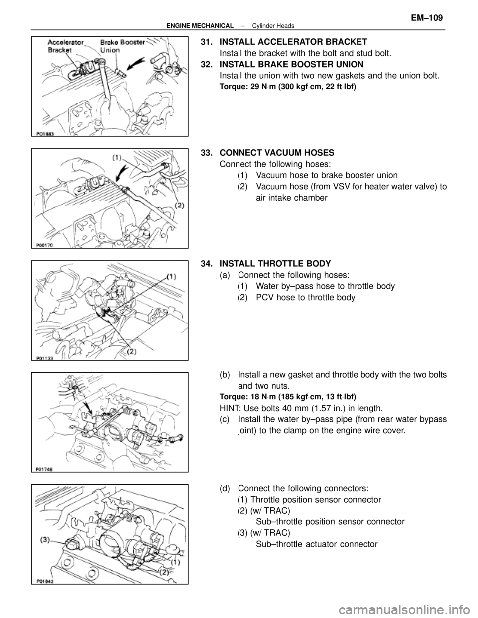
31. INSTALL ACCELERATOR BRACKETInstall the bracket with the bolt and stud bolt.
32. INSTALL BRAKE BOOSTER UNION Install the union with two new gaskets and the union bolt.
Torque: 29 N Vm (300 kgf Vcm, 22 ft Vlbf)
33. CONNECT VACUUM HOSES
Connect the following hoses:(1) Vacuum hose to brake booster union
(2) Vacuum hose (from VSV for heater water valve) to
air intake chamber
34. INSTALL THROTTLE BODY (a) Connect the following hoses:(1) Water by±pass hose to throttle body
(2) PCV hose to throttle body
(b) Install a new gasket and throttle body with the two bolts and two nuts.
Torque: 18 N Vm (185 kgf Vcm, 13 ft Vlbf)
HINT: Use bolts 40 mm (1.57 in.) in length.
(c) Install the water by±pass pipe (from rear water bypass
joint) to the clamp on the engine wire cover.
(d) Connect the following connectors: (1) Throttle position sensor connector
(2) (w/ TRAC) Sub±throttle position sensor connector
(3) (w/ TRAC) Sub±throttle actuator connector
±
ENGINE MECHANICAL Cylinder HeadsEM±109
WhereEverybodyKnowsYourName
Page 2407 of 4087
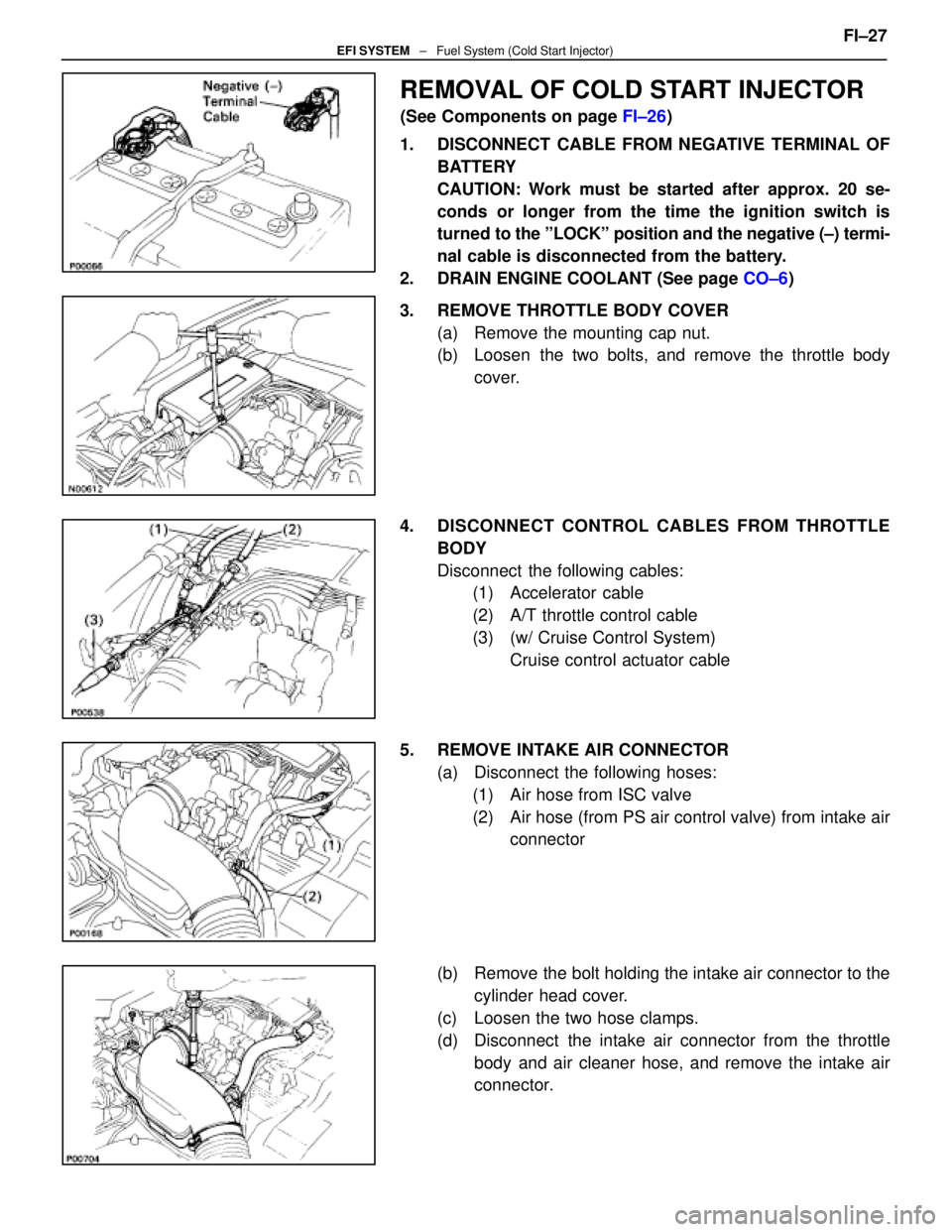
REMOVAL OF COLD START INJECTOR
(See Components on page FI±26)
1. DISCONNECT CABLE FROM NEGATIVE TERMINAL OF BATTERY
CAUTION: Work must be started after approx. 20 se-
conds or longer from the time the ignition switch is
turned to the ºLOCKº position and the negative (±) termi-
nal cable is disconnected from the battery.
2. DRAIN ENGINE COOLANT (See page CO±6)
3. REMOVE THROTTLE BODY COVER (a) Remove the mounting cap nut.
(b) Loosen the two bolts, and remove the throttle bodycover.
4. DISCONNECT CONTROL CABLES FROM THROTTLE BODY
Disconnect the following cables:(1) Accelerator cable
(2) A/T throttle control cable
(3) (w/ Cruise Control System)
Cruise control actuator cable
5. REMOVE INTAKE AIR CONNECTOR (a) Disconnect the following hoses:(1) Air hose from ISC valve
(2) Air hose (from PS air control valve) from intake air connector
(b) Remove the bolt holding the intake air connector to the cylinder head cover.
(c) Loosen the two hose clamps.
(d) Disconnect the intake air connector from the throttle body and air cleaner hose, and remove the intake air
connector. FI±27
EFI SYSTEM
± Fuel System (Cold Start Injector)
WhereEverybodyKnowsYourName
Page 2409 of 4087
11. REMOVE LH NO.3 TIMING BELT COVER(a) Remove the four mounting bolts.
(b) Disconnect the cord grommet from the timing belt cover,
and remove the timing belt cover.
(c) Remove the cord grommet from the high±tension cord.
12. REMOVE LOWER HIGH±TENSION CORD COVER (a) Disconnect the high±tension cord from the RH ignitioncoil.
(b) D i s c onnect the high±tension cords from the
high±tension cord cover.
(c) Remove the bolt and cord cover.
13. REMOVE THROTTLE BODY (a) Disconnect the following connectors:(1) Throttle position sensor connector
(2) (w/ TRAC) Sub±throttle position sensor connector
(3) (w/ TRAC) Sub±throttle actuator connector
(b) Disconnect the following hoses: (1) Heater water hose from heater water valve FI±29
EFI SYSTEM
± Fuel System (Cold Start Injector)
WhereEverybodyKnowsYourName
Page 2419 of 4087
(4) Heater water hose to heater water valve
(e) Connect the following connectors: (1) Throttle position sensor connector
(2) (w/ TRAC)
Sub±throttle position sensor connector
(3) (w/ TRAC) Sub±throttle actuator connector
5. INSTALL LOWER HIGH±TENSION CORD COVER (a) Connect the end portions of the high±tension cord to the
cord clamps
(b) Install the high±tension cord cover with the bolt.
(c) Install the clamps on the high±tension cords to the
high±tension cord cover.
(d) Connect the high±tension cord to the RH ignition coil.
7. INSTALL RH NO.3 TIMING BELT COVER (a) Install the three gaskets to the timing belt cover.
(b) Fit portion A of the timing belt cover, matching it with the
lower high±tension cord cover.
(c) Install the timing belt cover with the three bolts. FI±39
EFI SYSTEM
± Fuel System (Cold Start Injector)
WhereEverybodyKnowsYourName
Page 2450 of 4087
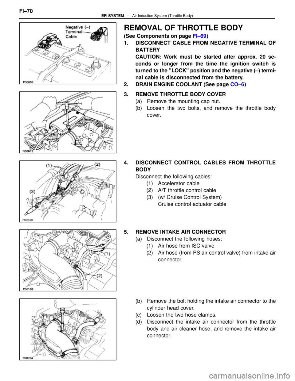
REMOVAL OF THROTTLE BODY
(See Components on page FI±69)
1. DISCONNECT CABLE FROM NEGATIVE TERMINAL OF BATTERY
CAUTION: Work must be started after approx. 20 se-
conds or longer from the time the ignition switch is
turned to the ºLOCKº position and the negative (±) termi-
nal cable is disconnected from the battery.
2. DRAIN ENGINE COOLANT (See page CO±6)
3. REMOVE THROTTLE BODY COVER (a) Remove the mounting cap nut.
(b) Loosen the two bolts, and remove the throttle bodycover.
4. DISCONNECT CONTROL CABLES FROM THROTTLE BODY
Disconnect the following cables:(1) Accelerator cable
(2) A/T throttle control cable
(3) (w/ Cruise Control System)
Cruise control actuator cable
5. REMOVE INTAKE AIR CONNECTOR (a) Disconnect the following hoses:(1) Air hose from ISC valve
(2) Air hose (from PS air control valve) from intake air connector
(b) Remove the bolt holding the intake air connector to the cylinder head cover.
(c) Loosen the two hose clamps.
(d) Disconnect the intake air connector from the throttle body and air cleaner hose, and remove the intake air
connector.
FI±70
EFI SYSTEM
± Air Induction System (Throttle Body)
WhereEverybodyKnowsYourName