Page 2451 of 4087
6. REMOVE UPPER HIGH±TENSION CORD COVER(a) Remove the two mounting bolts.
(b) Disconnect the front side claw groove of the cord coverfrom the claw of the lower cover, and remove the cord
cover.
7. REMOVE THROTTLE BODY (a) Disconnect the following connectors:(1) Throttle position sensor connector
(2) (w/ TRAC) Sub±throttle position sensor connector
(3) (w/ TRAC) Sub±throttle actuator connector
(b) Disconnect the following hoses: (1) Heater water hose from heater water valve
(2) Water by±pass hose from ISC valve
(3) (USA Spec.) Vacuum hose from throttle body
(4) (Exc. USA Spec.) Three vacuum hoses from throttle body FI±71
EFI SYSTEM
± Air Induction System (Throttle Body)
WhereEverybodyKnowsYourName
Page 2453 of 4087
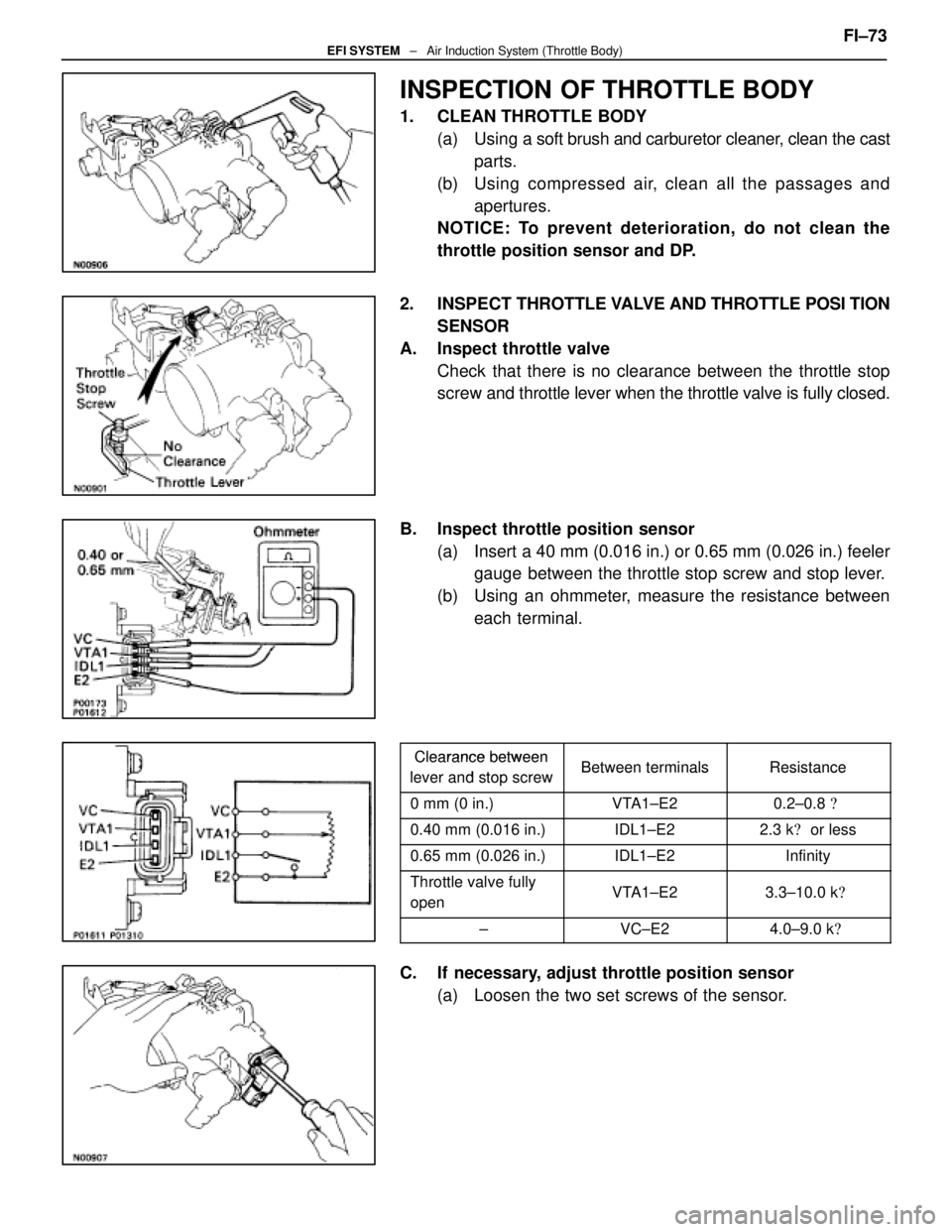
INSPECTION OF THROTTLE BODY
1. CLEAN THROTTLE BODY(a) Using a soft brush and carburetor cleaner, clean the cast
parts.
(b) Using compressed air, clean all the passages and apertures.
NOTICE: To prevent deterioration, do not clean the
throttle position sensor and DP.
2. INSPECT THROTTLE VALVE AND THROTTLE POSI TION
SENSOR
A. Inspect throttle valve Check that there is no clearance between the throttle stop
screw and throttle lever when the throttle valve is fully closed.
B. Inspect throttle position sensor (a) Insert a 40 mm (0.016 in.) or 0.65 mm (0.026 in.) feelergauge between the throttle stop screw and stop lever.
(b) Using an ohmmeter, measure the resistance between each terminal.
Clearance betweenClearance between
lever and stop screwBetween terminalsResistancelever and stop screwBetween terminalsResistance
0 mm (0 in.)VTA1±E20.2±0.8 �
0.40 mm (0.016 in.)IDL1±E22.3 k� or less
0.65 mm (0.026 in.)IDL1±E2Infinity
Throttle valve fully
openVTA1±E23.3±10.0 k �
±VC±E24.0±9.0 k�
C. If necessary, adjust throttle position sensor
(a) Loosen the two set screws of the sensor. FI±73
EFI SYSTEM
± Air Induction System (Throttle Body)
WhereEverybodyKnowsYourName
Page 2454 of 4087
(b) Insert a 0.40 mm (0.016 in.) feeler gauge, between thethrottle stop screw and stop lever.
(c) Connect the test probe of an ohmmeter to the terminals
IDL1 and E2 of the sensor.
(d) Gradually turn the sensor clockwise until the ohmmeter deflects, and secure it with the two set screws.
(e) Recheck the continuity between terminals IDL1 and E2.
Clearance between
lever and stop screwContinuity (IDL1±E2)
0.40 mm (0.016 in.)Continuity
0.65 mm (0.026 in.)No continuity
3. (w/ TRAC) INSPECT SUB±THROTTLE ACTUATOR, SUBTHROTTLE
VALVE AND SUB±THROTTLE POSITION SENSOR
A. Inspect sub±throttle actuator Using an ohmmeter, measure the resistance between the ter-
minals (ACM±A and �, BCM±B and B).
Resistance: 0.5±1.0 �
If the resistance is not as specified, replace the actuator
valve.
B. Inspect sub±throttle actuator Remove the three screws and sub±throttle actuator.
FI±74
EFI SYSTEM
± Air Induction System (Throttle Body)
WhereEverybodyKnowsYourName
Page 2455 of 4087
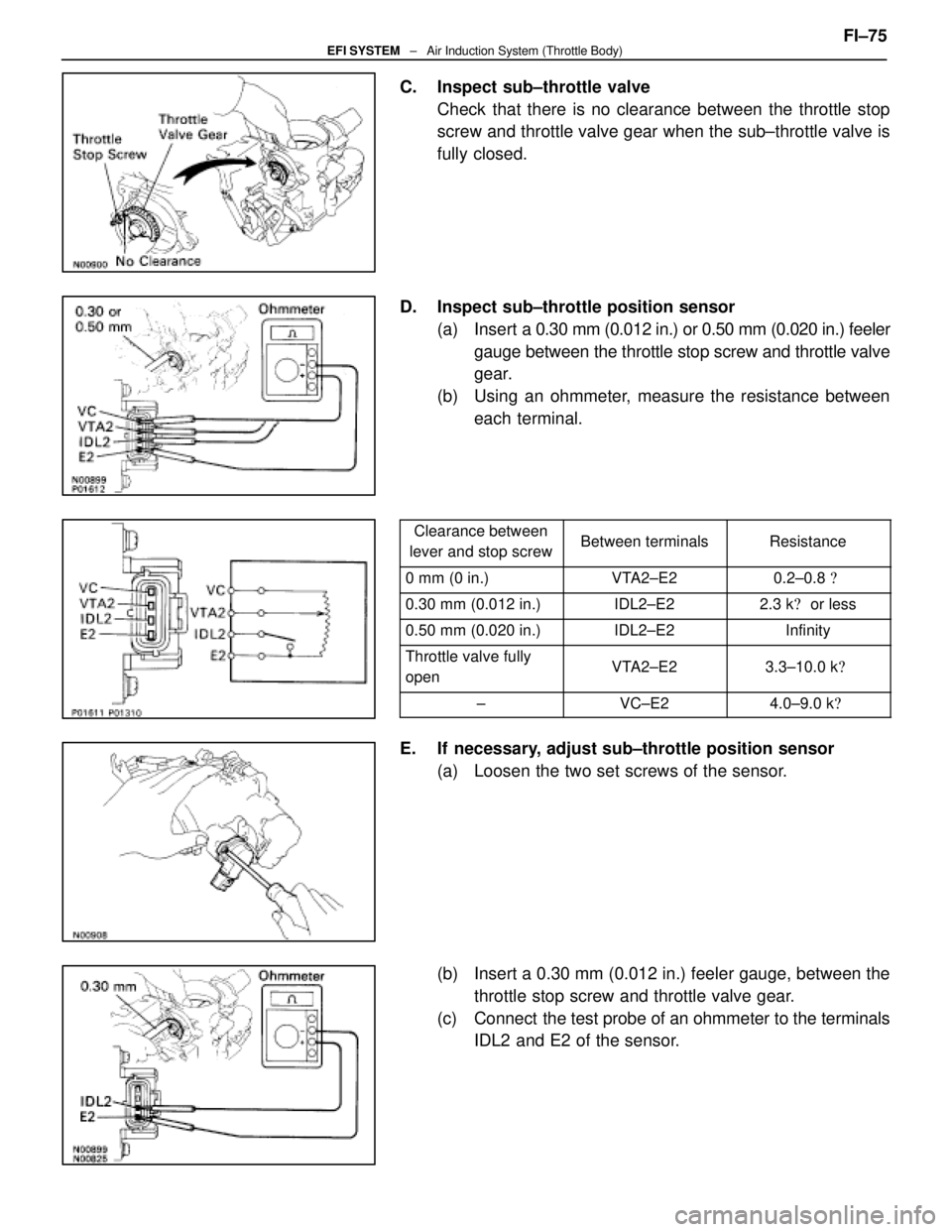
C. Inspect sub±throttle valveCheck that there is no clearance between the throttle stop
screw and throttle valve gear when the sub±throttle valve is
fully closed.
D. Inspect sub±throttle position sensor (a) Insert a 0.30 mm (0.012 in.) or 0.50 mm (0.020 in.) feeler
gauge between the throttle stop screw and throttle valve
gear.
(b) Using an ohmmeter, measure the resistance between each terminal.
Clearance between
lever and stop screwBetween terminalsResistance
0 mm (0 in.)VTA2±E20.2±0.8 �
0.30 mm (0.012 in.)IDL2±E22.3 k� or less
0.50 mm (0.020 in.)IDL2±E2Infinity
Throttle valve fully
openVTA2±E23.3±10.0 k �
±VC±E24.0±9.0 k�
E. If necessary, adjust sub±throttle position sensor
(a) Loosen the two set screws of the sensor.
(b) Insert a 0.30 mm (0.012 in.) feeler gauge, between thethrottle stop screw and throttle valve gear.
(c) Connect the test probe of an ohmmeter to the terminals IDL2 and E2 of the sensor. FI±75
EFI SYSTEM
± Air Induction System (Throttle Body)
WhereEverybodyKnowsYourName
Page 2458 of 4087
(4) Heater water hose to heater water valve
(f) Connect the following connectors: (1) Throttle position sensor connector
(2) (w/ TRAC)
Sub±throttle position sensor connector
(3) (w/ TRAC) Sub±throttle actuator connector
2. INSTALL UPPER HIGH±TENSION CORD COVER (a) Fit portion A of the upper high±tension cover, matchingit with the top of the lower high±tension cord cover.
(b) Push the front side of the high±tension cord cover, and connect the front side claw groove of the upper
high±tension cord cover to the claw of the lower
high±tension cord cover.
(c) Install the upper high±tension cord cover with the two bolts.
3. INSTALL INTAKE AIR CONNECTOR (a) Connect the end portions of the intake air connector tothe throttle body and air cleaner hose.
(b) Tighten the two hose clamps.
(c) Install the bolt holding the intake air connector to the
cylinder head cover.
FI±78
EFI SYSTEM
± Air Induction System (Throttle Body)
WhereEverybodyKnowsYourName
Page 2462 of 4087
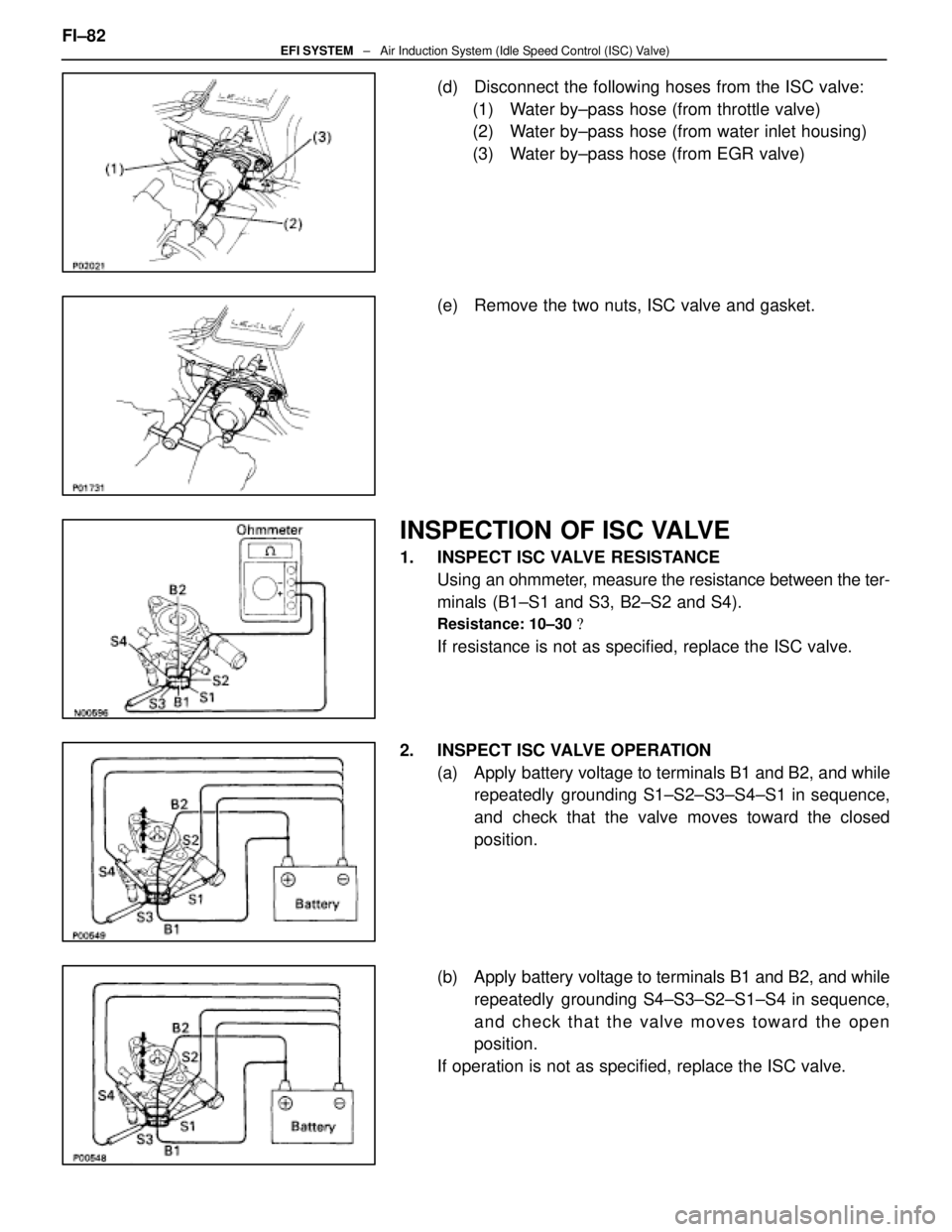
(d) Disconnect the following hoses from the ISC valve:(1) Water by±pass hose (from throttle valve)
(2) Water by±pass hose (from water inlet housing)
(3) Water by±pass hose (from EGR valve)
(e) Remove the two nuts, ISC valve and gasket.
INSPECTION OF ISC VALVE
1. INSPECT ISC VALVE RESISTANCE Using an ohmmeter, measure the resistance between the ter-
minals (B1±S1 and S3, B2±S2 and S4).
Resistance: 10±30 �
If resistance is not as specified, replace the ISC valve.
2. INSPECT ISC VALVE OPERATION (a) Apply battery voltage to terminals B1 and B2, and whilerepeatedly grounding S1±S2±S3±S4±S1 in sequence,
and check that the valve moves toward the closed
position.
(b) Apply battery voltage to terminals B1 and B2, and while repeatedly grounding S4±S3±S2±S1±S4 in sequence,
and check that the valve moves toward the open
position.
If operation is not as specified, replace the ISC valve.
FI±82
EFI SYSTEM
± Air Induction System (Idle Speed Control (ISC) Valve)
WhereEverybodyKnowsYourName
Page 2507 of 4087
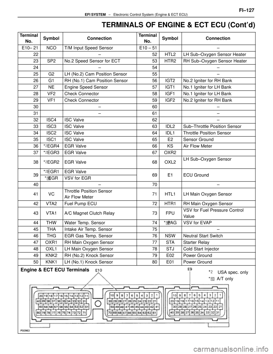
TERMINALS OF ENGINE & ECT ECU (Cont'd)
TerminalNo.SymbolConnectionTerminalNo.SymbolConnection
E10± 21NCOT/M Input Speed SensorE10 ± 51±
22±52HTL2LH Sub±Oxygen Sensor Heater
23SP2No.2 Speed Sensor for ECT53HTR2RH Sub±Oxygen Sensor Heater
24±54±
25G2LH (No.2) Cam Position Sensor55±
26G1RH (No.1) Cam Position Sensor56IGT2No.2 Igniter for RH Bank
27NEEngine Speed Sensor57IGT1No.1 Igniter for LH Bank
28VF2Check Connector58IGF1No.1 Igniter for LH Bank
29VF1Check Connector59IGF2No.2 Igniter for RH Bank
30±60±
31±61±
32ISC4ISC Valve62±
33ISC3ISC Valve63IDL2Sub±Throttle Position Sensor
34ISC2ISC Valve64IDL1Throttle Position Sensor
35ISC1ISC Valve65E2Sensor Ground
36*� EGR4EGR Valve66KSAir Flow Meter
37*� EGR3EGR Valve67OXR2
38*� EGR2EGR Valve68OXL2LH Sub±Oxygen Sensor
39*� EGR1EGR Valve69E1ECU Ground39*� EGRVSV for EGR69E1ECU Ground
40±70±
41VCThrottle Position Sensor
Air Flow Meter71HTL1LH Main Oxygen Sensor
42VTA2Fuel Pump ECU72HTR1RH Main Oxygen Sensor
43VTA1A/C Magnet Clutch Relay73FPUVSV for Fuel Pressure Control
Value
44THWWater Temp. Sensor74*� PA GVSV for EVAP
45THAIntake Air Temp. Sensor75±
46THGEGR Gas Temp. Sensor76NSWNeutral Start Switch
47OXR1RH Main Oxygen Sensor77STAStarter Relay
48OXL1LH Main Oxygen Sensor78STJCold Start Injector
49KNK2RH (No.2) Knock Sensor79E02Power Ground
50KNK1LH (No.1) Knock Sensor80E01Power Ground
Engine & ECT ECU Terminals
*��USA spec. only
* �� A/T only
FI±127EFI SYSTEM ± Electronic Control System (Engine & ECT ECU)
WhereEverybodyKnowsYourName
Page 2512 of 4087
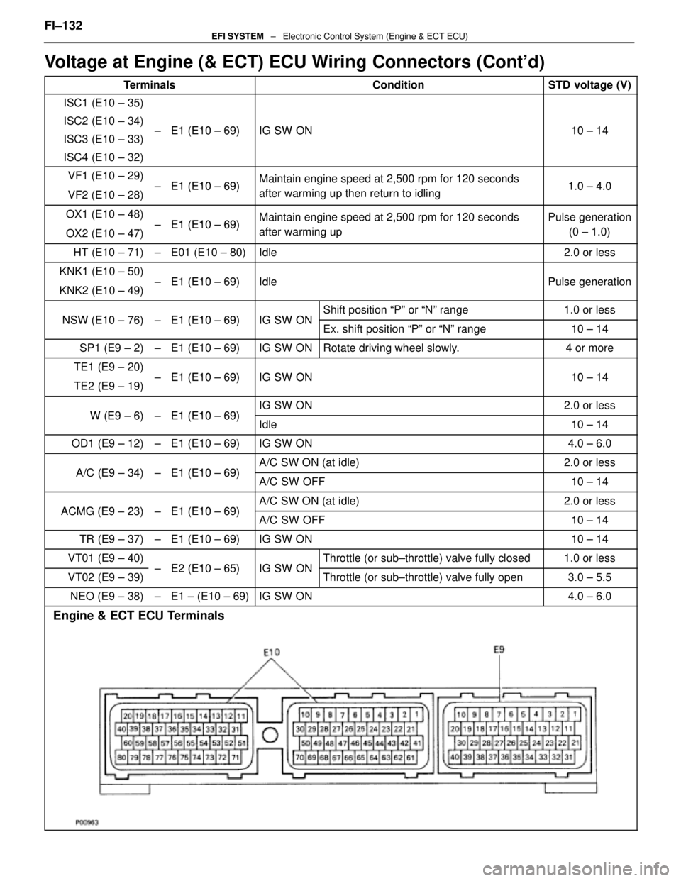
Voltage at Engine (& ECT) ECU Wiring Connectors (Cont'd)
TerminalsConditionSTD voltage (V)
ISC1 (E10 ± 35)
ISC2 (E10 ± 34)E1 (E10 69)IG SW ON10 14ISC3 (E10 ± 33)± E1 (E10 ± 69)IG SW ON10 ± 14
ISC4 (E10 ± 32)
VF1 (E10 ± 29)E1 (E10 69)Maintain engine speed at 2,500 rpm for 120 seconds10 40VF2 (E10 ± 28)± E1 (E10 ± 69)Maintain engine s eed at 2,500 rm for 120 seconds
after warming up then return to idling1.0 ± 4.0
OX1 (E10 ± 48)E1 (E10 69)Maintain engine speed at 2,500 rpm for 120 secondsPulse generation
OX2 (E10 ± 47)± E1 (E10 ± 69)Maintain engine s eed at 2,500 rm for 120 seconds
after warming up
Pulse generation
(0 ± 1.0)
HT (E10 ± 71)±E01 (E10 ± 80)Idle2.0 or less
KNK1 (E10 ± 50)E1 (E10 69)IdlePulse generationKNK2 (E10 ± 49)± E1 (E10 ± 69)IdlePulse generation
NSW (E10 76)E1 (E10 69)IG SW ONShift position ªPº or ªNº range1.0 or lessNSW (E10 ± 76)± E1 (E10 ± 69)IG SW ONEx. shift position ªPº or ªNº range10 ± 14
SP1 (E9 ± 2)±E1 (E10 ± 69)IG SW ONRotate driving wheel slowly.4 or more
TE1 (E9 ± 20)E1 (E10 69)IG SW ON10 14TE2 (E9 ± 19)± E1 (E10 ± 69)IG SW ON10 ± 14
W (E9 6)E1 (E10 69)IG SW ON2.0 or lessW (E9 ± 6)± E1 (E10 ± 69)Idle10 ± 14
OD1 (E9 ± 12)±E1 (E10 ± 69)IG SW ON4.0 ± 6.0
A/C (E9 34)E1 (E10 69)A/C SW ON (at idle)2.0 or lessA/C (E9 ± 34)± E1 (E10 ± 69)A/C SW OFF10 ± 14
ACMG (E9 23)E1 (E10 69)A/C SW ON (at idle)2.0 or lessACMG (E9 ± 23)± E1 (E10 ± 69)A/C SW OFF10 ± 14
TR (E9 ± 37)±E1 (E10 ± 69)IG SW ON10 ± 14
VT01 (E9 ± 40)E2 (E10 65)IG SW ONThrottle (or sub±throttle) valve fully closed1.0 or less
VT02 (E9 ± 39)± E2 (E10 ± 65)IG SW ONThrottle (or sub±throttle) valve fully open3.0 ± 5.5
NEO (E9 ± 38)±E1 ± (E10 ± 69)IG SW ON4.0 ± 6.0
Engine & ECT ECU Terminals
FI±132EFI SYSTEM ± Electronic Control System (Engine & ECT ECU)
WhereEverybodyKnowsYourName