Page 3544 of 4087
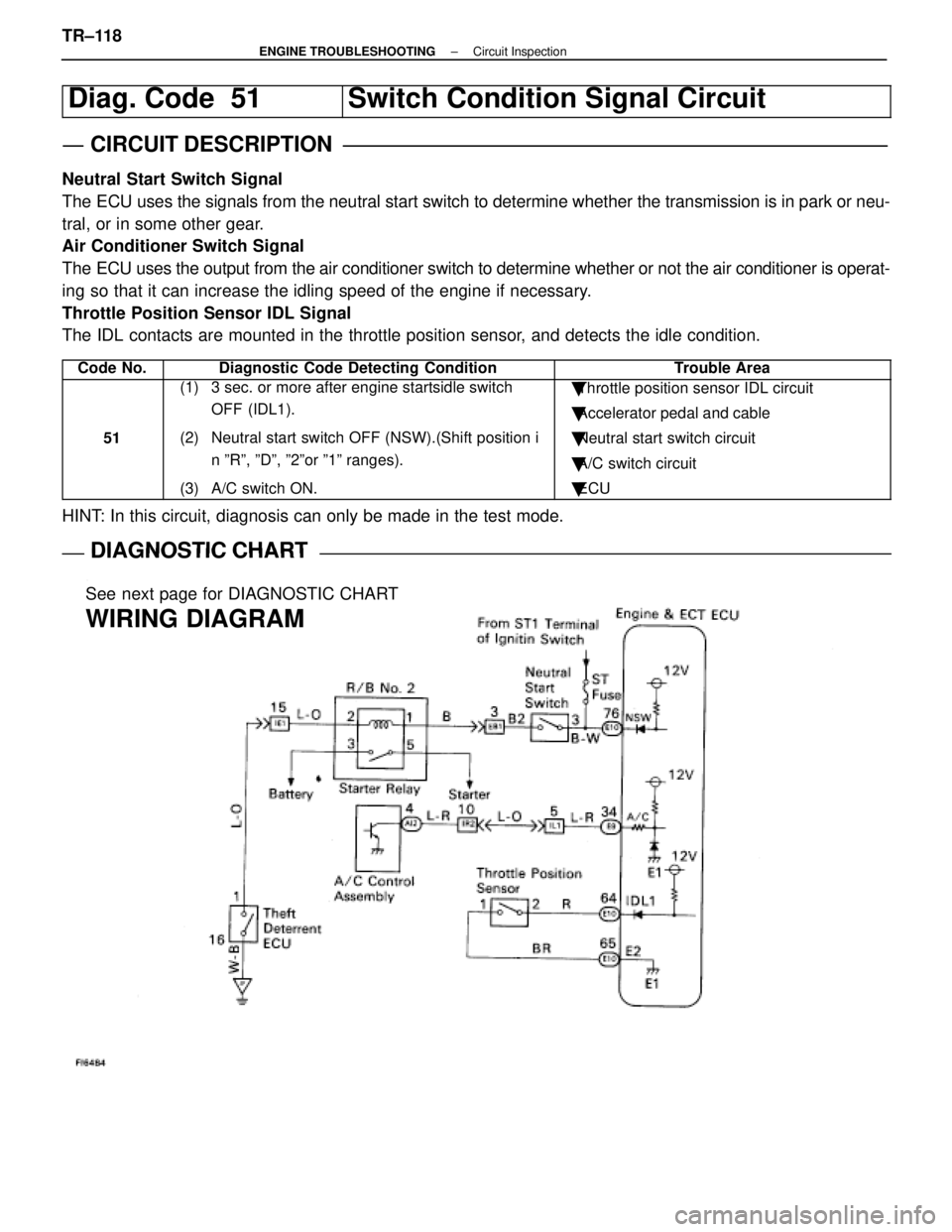
Diag. Code 51Switch Condition Signal Circuit
CIRCUIT DESCRIPTION
Neutral Start Switch Signal
The ECU uses the signals from the neutral start switch to determine whether\
the transmission is in park or neu-
tral, or in some other gear.
Air Conditioner Switch Signal
The ECU uses the output from the air conditioner switch to determine whethe\
r or not the air conditioner is operat-
ing so that it can increase the idling speed of the engine if necessary.
Throttle Position Sensor IDL Signal
The IDL contacts are mounted in the throttle position sensor, and detects the idle condition.
Code No.Diagnostic Code Detecting ConditionTrouble Area
51
(1) 3 sec. or more after engine startsidle switch OFF (IDL1).
(2) Neutral start switch OFF (NSW).(Shift position i n ºRº, ºDº, º2ºor º1º ranges).
(3) A/C switch ON.� Throttle position sensor IDL circuit
� Accelerator pedal and cable
� Neutral start switch circuit
� A/C switch circuit
� ECU
HINT: In this circuit, diagnosis can only be made in the test mode.
DIAGNOSTIC CHARTDIAGNOSTIC CHART
See next page for DIAGNOSTIC CHART
WIRING DIAGRAM
TR±118±
ENGINE TROUBLESHOOTING Circuit Inspection
WhereEverybodyKnowsYourName
Page 3545 of 4087
DIAGNOSTIC CHART
DIAGNOSTIC
CHART
NG (NSW)
Check for input signal.
Proceed to next circuit inspection shown
on maxtrix chart (See page TR±35).
Check resistance of throttle
position sensor.
Check input circuit of A/C.
Check and repair harness or connector
between sensor and ECU.
Check for open and short in harness
and connector beteen A/C control assy.
and ECU.
Repair or replace harness or
connector.
Check and replace A/C control
assembly.
Adjust or replace throttle position
sensor (See page FI-73).
See page TR±122.
Check and replace ECU.
±
ENGINE TROUBLESHOOTING Circuit InspectionTR±119
WhereEverybodyKnowsYourName
Page 3546 of 4087
OKNG
OKNG
INSPECTION PROCEDURE
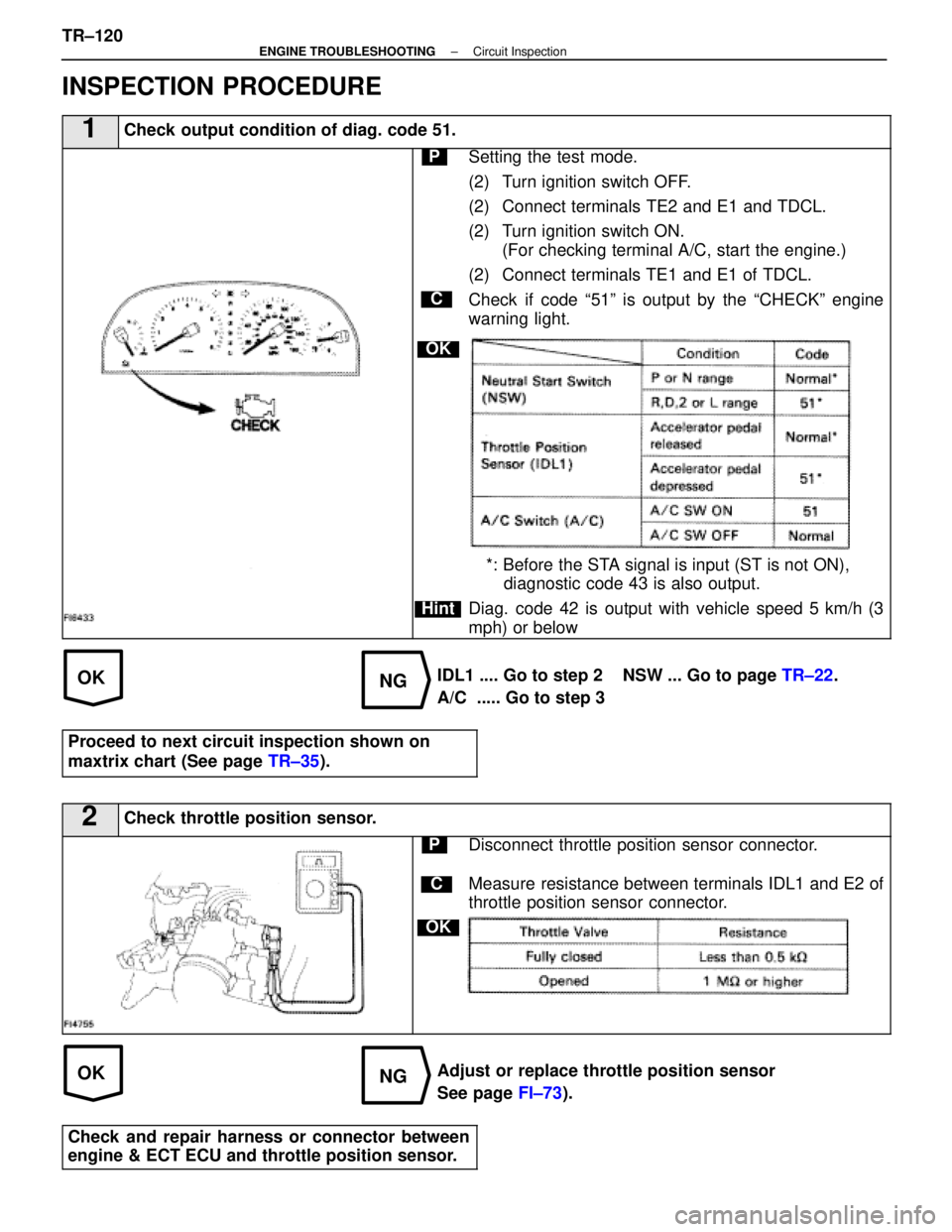
1Check output condition of diag. code 51.
C
OK
Hint
PSetting the test mode.
(2) Turn ignition switch OFF.
(2) Connect terminals TE2 and E1 and TDCL.
(2) Turn ignition switch ON.(For checking terminal A/C, start the engine.)
(2) Connect terminals TE1 and E1 of TDCL.
Check if code ª51º is output by the ªCHECKº engine
warning light.
*: Before the STA signal is input (ST is not ON), diagnostic code 43 is also output.
Diag. code 42 is output with vehicle speed 5 km/h (3
mph) or below
IDL1 .... Go to step 2 NSW ... Go to page TR±22.
A/C ..... Go to step 3
Proceed to next circuit inspection shown on
maxtrix chart (See page TR±35).
2Check throttle position sensor.
C
OK
PDisconnect throttle position sensor connector.
Measure resistance between terminals IDL1 and E2 of
throttle position sensor connector.
Adjust or replace throttle position sensor
See page FI±73).
Check and repair harness or connector between
engine & ECT ECU and throttle position sensor.
TR±120±
ENGINE TROUBLESHOOTING Circuit Inspection
WhereEverybodyKnowsYourName
Page 3578 of 4087
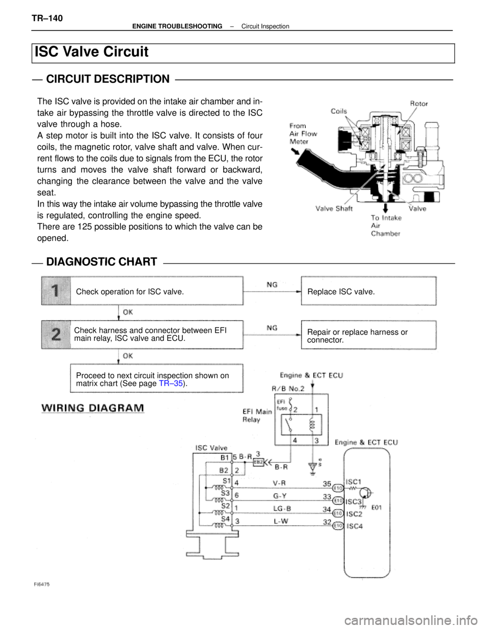
ISC Valve Circuit
CIRCUIT DESCRIPTION
The ISC valve is provided on the intake air chamber and in-
take air bypassing the throttle valve is directed to the ISC
valve through a hose.
A step motor is built into the ISC valve. It consists of four
coils, the magnetic rotor, valve shaft and valve. When cur-
rent flows to the coils due to signals from the ECU, the rotor
turns and moves the valve shaft forward or backward,
changing the clearance between the valve and the valve
seat.
In this way the intake air volume bypassing the throttle valve
is regulated, controlling the engine speed.
There are 125 possible positions to which the valve can be
opened.
DIAGNOSTIC CHARTDIAGNOSTIC CHART
Check operation for ISC valve.Replace ISC valve.
Repair or replace harness or
connector.
Proceed to next circuit inspection shown on
matrix chart (See page TR±35).
Check harness and connector between EFI
main relay, ISC valve and ECU.
TR±140±
ENGINE TROUBLESHOOTING Circuit Inspection
WhereEverybodyKnowsYourName
Page 3597 of 4087
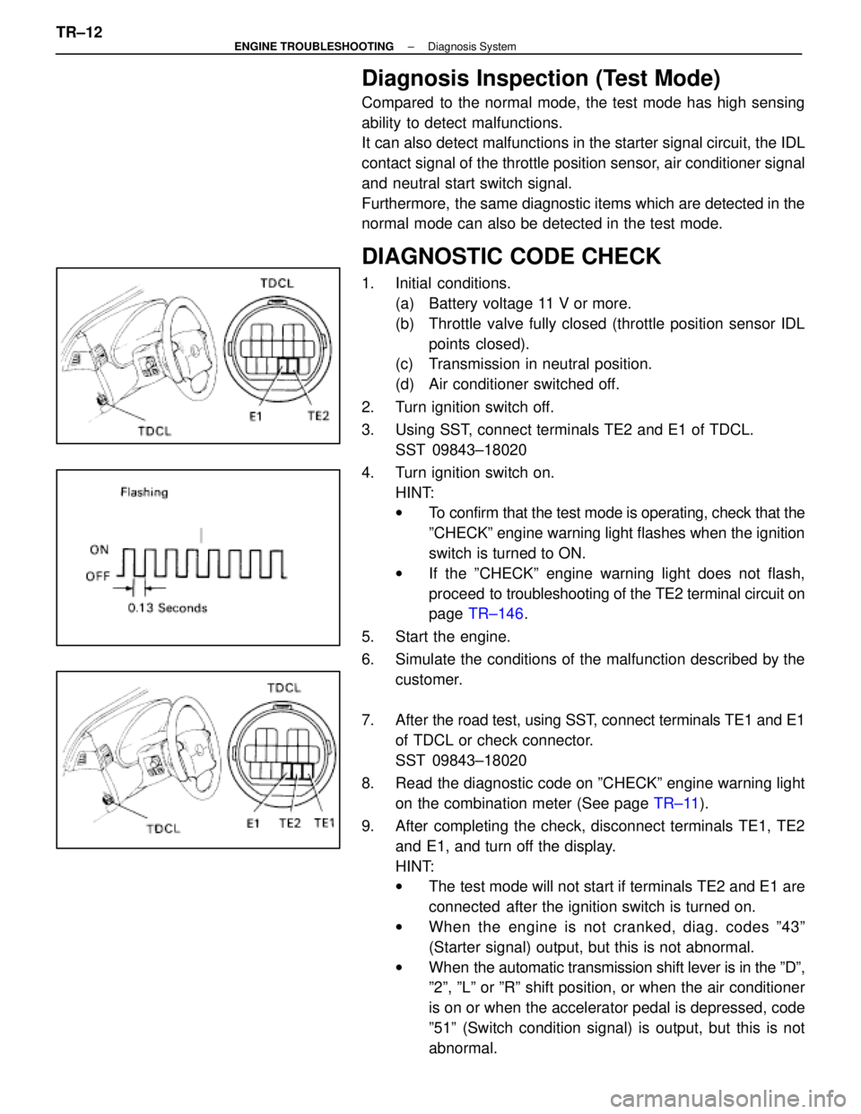
Diagnosis Inspection (Test Mode)
Compared to the normal mode, the test mode has high sensing
ability to detect malfunctions.
It can also detect malfunctions in the starter signal circuit, the IDL
contact signal of the throttle position sensor, air conditioner signal
and neutral start switch signal.
Furthermore, the same diagnostic items which are detected in the
normal mode can also be detected in the test mode.
DIAGNOSTIC CODE CHECK
1. Initial conditions.(a) Battery voltage 11 V or more.
(b) Throttle valve fully closed (throttle position sensor IDLpoints closed).
(c) Transmission in neutral position.
(d) Air conditioner switched off.
2. Turn ignition switch off.
3. Using SST, connect terminals TE2 and E1 of TDCL. SST 09843±18020
4. Turn ignition switch on. HINT:
wTo confirm that the test mode is operating, check that the
ºCHECKº engine warning light flashes when the ignition
switch is turned to ON.
w If the ºCHECKº engine warning light does not flash,
proceed to tro ubleshooting of the TE2 terminal circuit on
page TR±146 .
5. Start the engine.
6. Simulate the conditions of the malfunction described by the customer.
7. After the road test, using SST, connect terminals TE1 and E1
of TDCL or check connector.
SST 09843±18020
8. Read the diagnostic code on ºCHECKº engine warning light on the combination meter (See page TR±11).
9. After completing the check, disconnect terminals TE1, TE2 and E1, and turn off the display.
HINT:
wThe test mode will not start if terminals TE2 and E1 are
connected after the ignition switch is turned on.
w When the engine is not cranked, diag. codes º43º
(Starter signal) output, but this is not abnormal.
w When the automatic transmission shift lever is in the ºDº,
º2º, ºLº or ºRº shift position, or when the air conditioner
is on or when the accelerator pedal is depressed, code
º51º (Switch condition signal) is output, but this is not
abnormal.
TR±12
±
ENGINE TROUBLESHOOTING Diagnosis System
WhereEverybodyKnowsYourName
Page 3604 of 4087
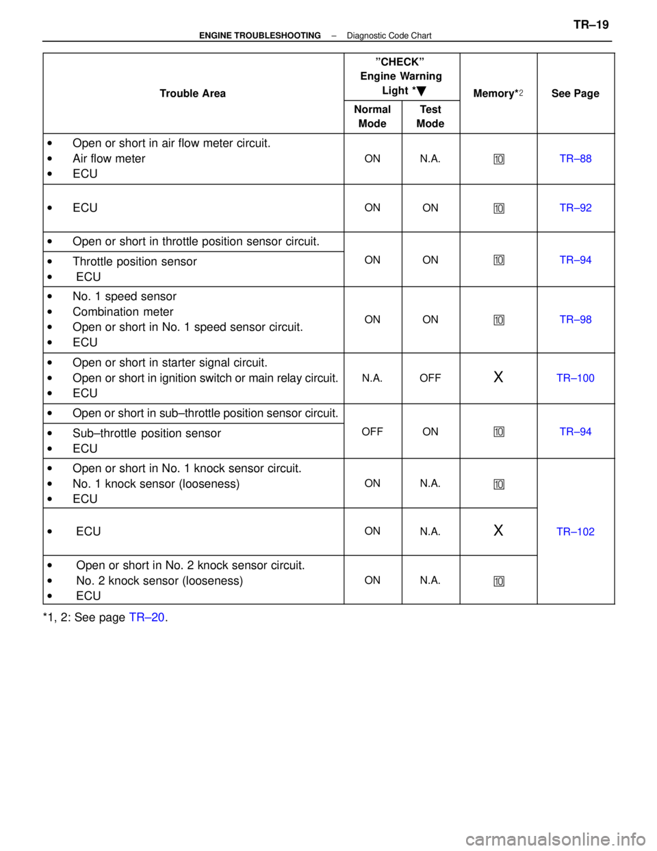
Trouble Area
ºCHECKº
Engine Warning
Light * �
Memory* �See PageTrouble Area
Normal
ModeTest
Mode
MemorySee Page
w Open or short in air flow meter circuit.
w Air flow meter
w ECU
ONN.A.�TR±88
wECUONON�TR±92
wOpen or short in throttle position sensor circuit.
wThrottle position sensorONON�TR±94Throttle osition sensor
w ECU
wNo. 1 speed sensor
w Combination meter
w Open or short in No. 1 speed sensor circuit.
w ECU
ONON�TR±98
wOpen or short in starter signal circuit.
w Open or short in ignition switch or main relay circuit.
w ECU
N.A.OFFXTR±100
wOpen or short in sub±throttle position sensor circuit.
wSub±throttle position sensorOFFON�TR±94Sub throttle osition sensor
wECU
wOpen or short in No. 1 knock sensor circuit.wOen or short in No. 1 knock sensor circuit.
w No. 1 knock sensor (looseness)
ONN.A.�No. 1 knock sensor (looseness)
wECU
�
w ECUONN.A.XTR±102
w Open or short in No. 2 knock sensor circuit.w Oen or short in No. 2 knock sensor circuit.
w No. 2 knock sensor (looseness)
ONN.A.� No. 2 knock sensor (looseness)
w ECU
�
*1, 2: See page TR±20.
±
ENGINE TROUBLESHOOTING Diagnostic Code ChartTR±19
WhereEverybodyKnowsYourName
Page 3606 of 4087
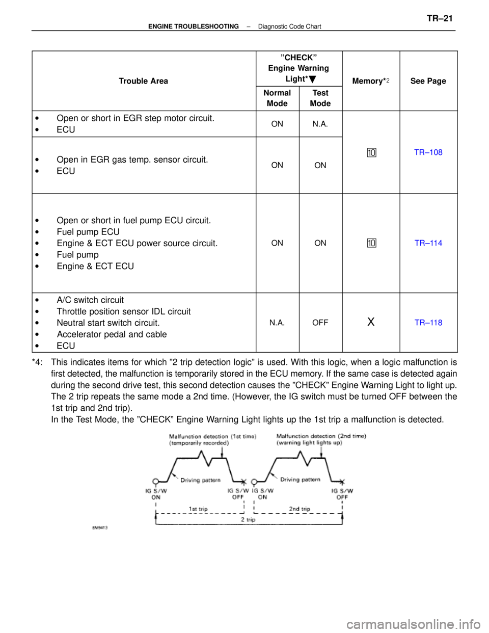
Trouble Area
ºCHECKº
Engine Warning
Light* �
Memory* �See PageTrouble Area
Normal
ModeTest
Mode
MemorySee Page
w Open or short in EGR step motor circuit.ONNA Oen or short in EGR ste motor circuit.
w ECUONN.A.
w Open in EGR gas temp. sensor circuit.ONON
�TR±108 Oen in EGR gas tem . sensor circuit.
w ECUONON
w Open or short in fuel pump ECU circuit.
w Fuel pump ECU
w Engine & ECT ECU power source circuit.
w Fuel pump
w Engine & ECT ECU
ONON�TR±114
w A/C switch circuit
w Throttle position sensor IDL circuit
w Neutral start switch circuit.
w Accelerator pedal and cable
w ECU
N.A.OFFXTR±118
*4: This indicates items for which º2 trip detection logicº is used. With this logic, when a lo\
gic malfunction is
first detected, the malfunction is temporarily stored in the ECU memory. If the same case is detected again
during the second drive test, this second detection causes the ºCHECK\
º Engine Warning Light to light up.
The 2 trip repeats the same mode a 2nd time. (However, the IG switch must be turned OFF between the
1st trip and 2nd trip).
In the Test Mode, the ºCHECKº Engine Warning Light lights up the 1st trip a malfunction is detected.
±
ENGINE TROUBLESHOOTING Diagnostic Code ChartTR±21
WhereEverybodyKnowsYourName
Page 3607 of 4087

FAIL±SAFE CHART
If any of the following codes is recorded, the ECU enters fail±
safe mode.
Code No.Fail±Safe OperationFail±Safe Deactivation Conditions
14Fuel cut1 IGF1 detected in consecutive 8 ignitions.
15Fuel cut1 IGF2 detected in consecutive 8 ignitions.
16Torque control prohibited.Returned to normal condition.
22THW is fixed at 805C (176 5F).Returned to normal condition.
24THA is fixed at 20 5C (68 5F).Returned to normal condition.
31
Ignition timing controlled between 10 5 ~ 30 5
BTDC,
Injection time controlled between 3 msec. ~ 30 m
sec., in relation to:
w Engine rpm
w Throttle angle
w ISC step value
KS input 15 times/sec. or more.
35Atmospheric pressure is fixed at 760 mmHg.Returned to normal condition.
The following 1 or 2 must be repeated at least 2
times consecutively.
41VTA1 is fixed at 051 When IDL is ON41VTA1 is fixed at 051 When IDL is ON
0.25 V � VTA1 � 0.95 V
2 When IDL is OFF2 When IDL is OFF
0.25 V � VTA1 � 4.9 V
The following 1 or 2 must be repeated at least 2
times consecutively.
47Value of VTA1 is used1 When IDL2 is ON47Value of VTA1 is used.1 When IDL2 is ON
0.25 V � VTA2 � 0.95 V
2 When IDL2 is OFF2 When IDL2 is OFF
0.25 V � VTA2 � 4.9 V
52Max. timeing retardation.IG switch OFF.
53Max. timeing retardation.Returned to normal condition.
55Max. timeing retardation.IG switch OFF.
Back±Up Function
If there is trouble with the program in the ECU and the ignition signals\
(IGT) are not output, the ECU controls
fuel injection and ignition timing at predetermined levels as a back±up f\
unction to make it possible to continue
to operate the vehicle.
Furthermore, the injection duration is calculated from the satrting sign\
al (STA) and the throttle position signal
(IDL). Also, the ignition timing is fixed at the initial ignition timing, 5 5 BTDC, without relation to the engine speed.
HINT: If the engine is controlled by the back±up function, the CHECK ENGIN\
E light lights up to warn the driver
of the malfunction but the diagnostic code is not output. TR±22
±
ENGINE TROUBLESHOOTING Fail±Safe Chart
WhereEverybodyKnowsYourName