Page 538 of 4087
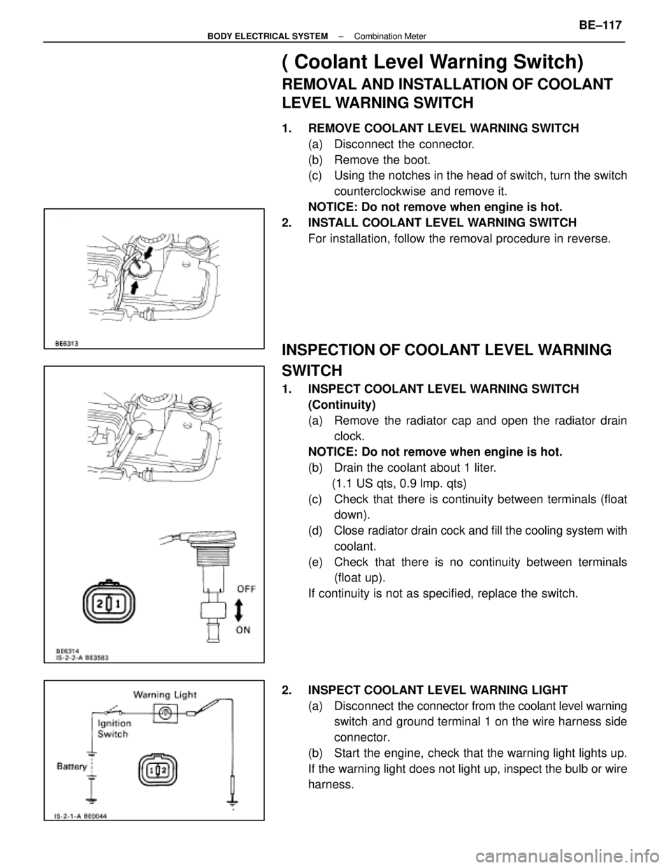
( Coolant Level Warning Switch)
REMOVAL AND INSTALLATION OF COOLANT
LEVEL WARNING SWITCH
1. REMOVE COOLANT LEVEL WARNING SWITCH(a) Disconnect the connector.
(b) Remove the boot.
(c) Using the notches in the head of switch, turn the switchcounterclockwise and remove it.
NOTICE: Do not remove when engine is hot.
2. INSTALL COOLANT LEVEL WARNING SWITCH For installation, follow the removal procedure in reverse.
INSPECTION OF COOLANT LEVEL WARNING
SWITCH
1. INSPECT COOLANT LEVEL WARNING SWITCH(Continuity)
(a) Remove the radiator cap and open the radiator drainclock.
NOTICE: Do not remove when engine is hot.
(b) Drain the coolant about 1 liter. (1.1 US qts, 0.9 lmp. qts)
(c) Check that there is continuity between terminals (float down).
(d) Close radiator drain cock and fill the cooling system with
coolant.
(e) Check that there is no continuity between terminals (float up).
If continuity is not as specified, replace the switch.
2. INSPECT COOLANT LEVEL WARNING LIGHT (a) Disconnect the connector from the coolant level warning
switch and ground terminal 1 on the wire harness side
connector.
(b) Start the engine, check that the warning light lights up.
If the warning light does not light up, inspect the bulb or wire
harness.
±
BODY ELECTRICAL SYSTEM Combination MeterBE±117
WhereEverybodyKnowsYourName
Page 541 of 4087
Parts Inspection
(Power Window Master Switch)
REMOVAL AND INSTALLATION OF
POWER WINDOW MASTER SWITCH
(See page BO±33)
INSPECTION OF POWER WINDOW
MASTER SWITCH
INSPECT POWER WINDOW MASTER SWITCH
(Continuity)
Inspect the switch continuity between terminals.
Window operation Driver's Passenger's
Terminal
Switch position
UP
OFF
DOWN
UP
OFF
DOWN
Window Unlock
Window Lock
If continuity is not as specified, replace the master siwtch.
(Illumination)
(a) Set the window lock switch to the unlock position.
(b) Connect the positive (+) lead from the battery to terminal
4 and the negative (±) lead to terminal 8, check that all
the illuminations light up.
±
BODY ELECTRICAL SYSTEM Power Window Control SystemBE±149
WhereEverybodyKnowsYourName
Page 549 of 4087

Troubleshooting
You will find the cause of trouble more easily by properly using the table \
shown below. In this table, the
numbers indicate the order of priority of the causes of trouble. Check each part in \
the order shown. If neces-
sary, replace the part.
See page
BE±4 ,21BE±4,21BE±4,20BE±4,20BE±156BE±152BE±149BE±151BE±152BE±26BE±392BE±4,20 ±±
Part
name
Trouble
AM1 FuseDOME FuseDOOR FusePOWER FuseTheft Deterrent and Door Lock Control ECUPower Window Main RelayPower Window Master SwitchPower Window SwitchPower Window MotorIgnition SwitchDoor Open Detection SwitchECU±IG FuseWire Harness
*1 Power window does not operate.1234
*2 Power window does not operate.35467218
ªOne Touch Power Window Systemº does
not operate.1
Only one window glass does not move.1234
ªWindow Lock Systemº does not operate1
ªWindow Lock Illuminationº does not light
up.1
Key±off power window does not operate124536
*1: Dook Lock does not operate.
*2: Dook Lock is normal.
±
BODY ELECTRICAL SYSTEM Power Window Control SystemBE±157
WhereEverybodyKnowsYourName
Page 559 of 4087
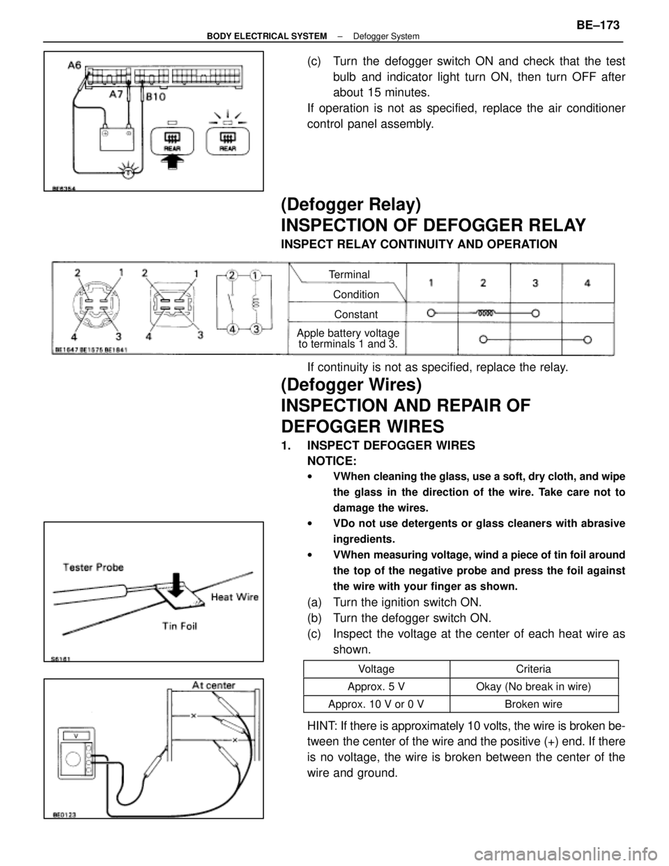
(c) Turn the defogger switch ON and check that the testbulb and indicator light turn ON, then turn OFF after
about 15 minutes.
If operation is not as specified, replace the air conditioner
control panel assembly.
(Defogger Relay)
INSPECTION OF DEFOGGER RELAY
INSPECT RELAY CONTINUITY AND OPERATION
Terminal
ConditionConstant
Apple battery voltage to terminals 1 and 3.
If continuity is not as specified, replace the relay.
(Defogger Wires)
INSPECTION AND REPAIR OF
DEFOGGER WIRES
1. INSPECT DEFOGGER WIRES
NOTICE:
w VWhen cleaning the glass, use a soft, dry cloth, and wipe
the glass in the direction of the wire. Take care not to
damage the wires.
w VDo not use detergents or glass cleaners with abrasive
ingredients.
w VWhen measuring voltage, wind a piece of tin foil around
the top of the negative probe and press the foil against
the wire with your finger as shown.
(a) Turn the ignition switch ON.
(b) Turn the defogger switch ON.
(c) Inspect the voltage at the center of each heat wire as
shown.
VoltageCriteria
Approx. 5 VOkay (No break in wire)
Approx. 10 V or 0 VBroken wire
HINT: If there is approximately 10 volts, the wire is broken be-
tween the center of the wire and the positive (+) end. If there
is no voltage, the wire is broken between the center of the
wire and ground.
±
BODY ELECTRICAL SYSTEM Defogger SystemBE±173
WhereEverybodyKnowsYourName
Page 592 of 4087
Parts Inspection
(Power Switch)
REMOVAL AND INSTALLATION OF
POWER SWITCH
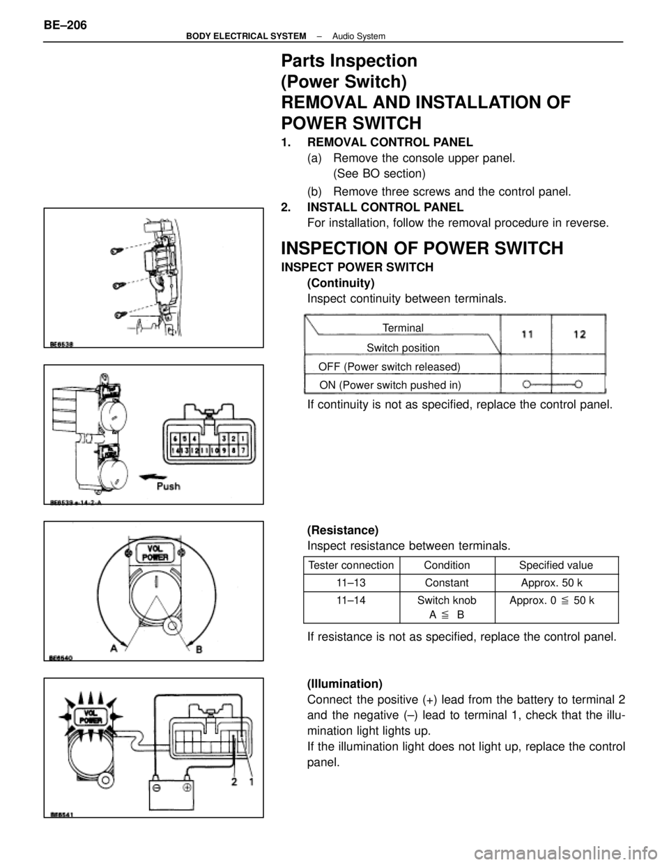
1. REMOVAL CONTROL PANEL(a) Remove the console upper panel.(See BO section)
(b) Remove three screws and the control panel.
2. INSTALL CONTROL PANEL For installation, follow the removal procedure in reverse.
INSPECTION OF POWER SWITCH
INSPECT POWER SWITCH
(Continuity)
Inspect continuity between terminals.
Terminal
Switch position
OFF (Power switch released) ON (Power switch pushed in)
If continuity is not as specified, replace the control panel.
(Resistance)
Inspect resistance between terminals.
Tester connectionConditionSpecified value
11±13ConstantApprox. 50 k �
11±14Switch knob
A � BApprox. 0 � 50 k �
If resistance is not as specified, replace the control panel.
(Illumination)
Connect the positive (+) lead from the battery to terminal 2
and the negative (±) lead to terminal 1, check that the illu-
mination light lights up.
If the illumination light does not light up, replace the control
panel.
BE±206
±
BODY ELECTRICAL SYSTEM Audio System
WhereEverybodyKnowsYourName
Page 593 of 4087
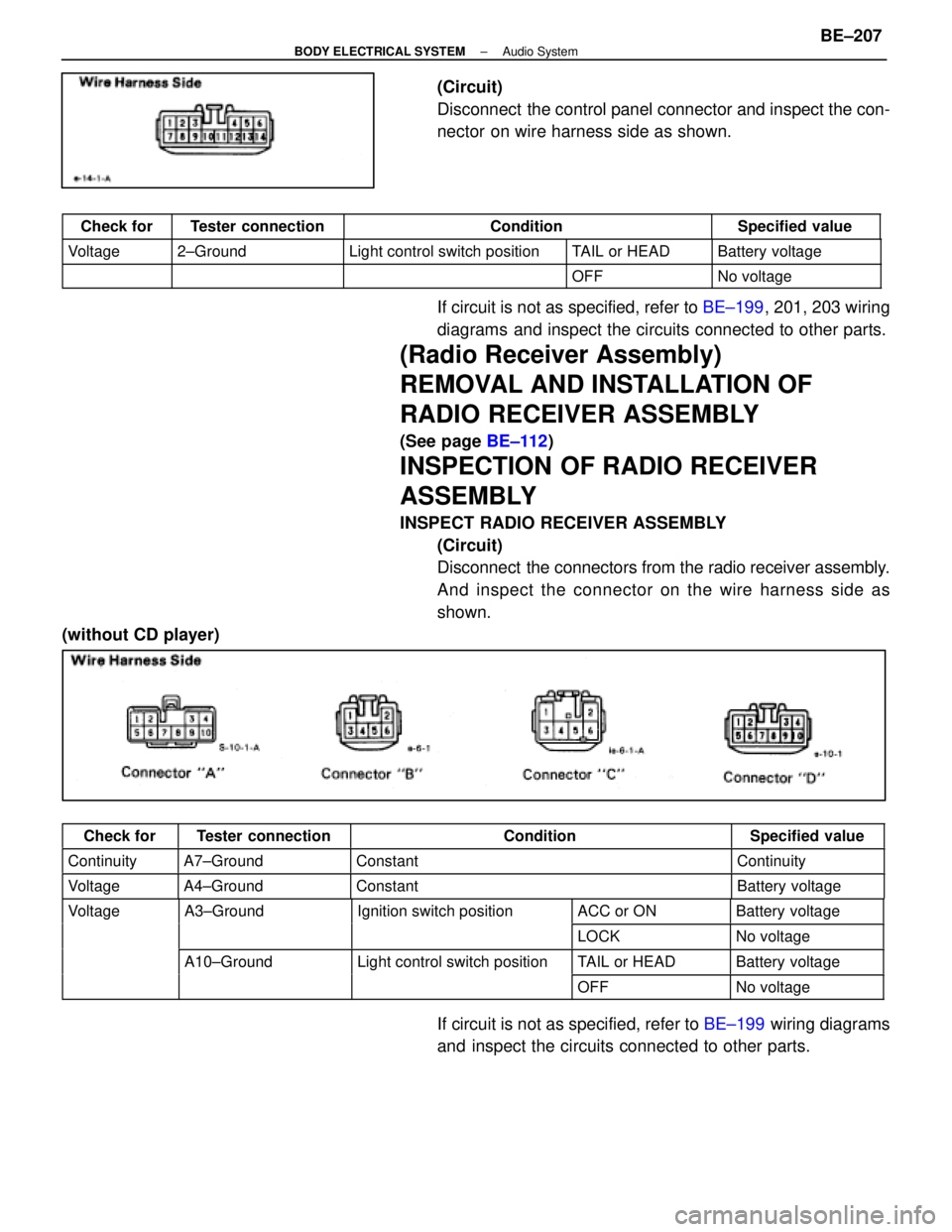
(Circuit)
Disconnect the control panel connector and inspect the con-
nector on wire harness side as shown.
Check forTester connectionConditionSpecified value
Voltage2±GroundLight control switch positionTAIL or HEADBattery voltage
OFFNo voltage
If circuit is not as specified, refer to BE±199, 201, 203 wiring
diagrams and inspect the circuits connected to other parts.
(Radio Receiver Assembly)
REMOVAL AND INSTALLATION OF
RADIO RECEIVER ASSEMBLY
(See page BE±112)
INSPECTION OF RADIO RECEIVER
ASSEMBLY
INSPECT RADIO RECEIVER ASSEMBLY
(Circuit)
Disconnect the connectors from the radio receiver assembly.
And inspect the connector on the wire harness side as
shown.
(without CD player)
Check forTester connectionConditionSpecified value
ContinuityA7±GroundConstantContinuity
VoltageA4±GroundConstantBattery voltage
VoltageA3±GroundIgnition switch positionACC or ONBattery voltageg
LOCKNo voltage
A10±GroundLight control switch positionTAIL or HEADBattery voltageg
OFFNo voltage
If circuit is not as specified, refer to BE±199 wiring diagrams
and inspect the circuits connected to other parts.
±
BODY ELECTRICAL SYSTEM Audio SystemBE±207
WhereEverybodyKnowsYourName
Page 594 of 4087
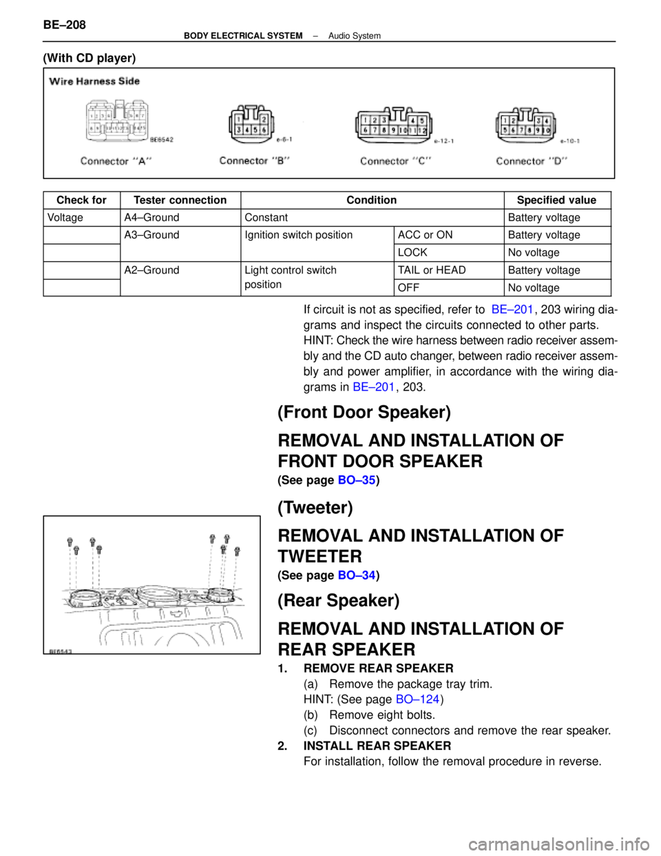
(With CD player)
Check forTester connectionConditionSpecified value
VoltageA4±GroundConstantBattery voltage
A3±GroundIgnition switch positionACC or ONBattery voltageg
LOCKNo voltage
A2±GroundLight control switchTAIL or HEADBattery voltageg
positionOFFNo voltage
If circuit is not as specified, refer to BE±201, 203 wiring dia-
grams and inspect the circuits connected to other parts.
HINT: Check the wire harness between radio receiver assem-
bly and the CD auto changer, between radio receiver assem-
bly and power amplifier, in accordance with the wiring dia-
grams in BE±201, 203.
(Front Door Speaker)
REMOVAL AND INSTALLATION OF
FRONT DOOR SPEAKER
(See page BO±35)
(Tweeter)
REMOVAL AND INSTALLATION OF
TWEETER
(See page BO±34)
(Rear Speaker)
REMOVAL AND INSTALLATION OF
REAR SPEAKER
1. REMOVE REAR SPEAKER
(a) Remove the package tray trim.
HINT: (See page BO±124)
(b) Remove eight bolts.
(c) Disconnect connectors and remove the rear speaker.
2. INSTALL REAR SPEAKER For installation, follow the removal procedure in reverse.
BE±208
±
BODY ELECTRICAL SYSTEM Audio System
WhereEverybodyKnowsYourName
Page 595 of 4087
(Woofer)
REMOVAL AND INSTALLATION OF
WOOFER
1. REMOVE WOOFER(a) Remove woofer cover together with high mount stoplight.
(b) Remove four bolts.
(c) Disconnect connector and remove woofer.
2. INSTALL WOOFER For installation follow the removal procedure in reverse.
(Woofer Amplifier)
REMOVAL AND INSTALLATION OF
WOOFER AMPLIFIER
(without CD player)
1. REMOVE WOOFER AMPLIFIER(a) Remove the RH side cover.
(b) Disconnect the connector and remove three nuts and
the woofer amplifier with the bracket.
(c) Remove four bolts and the woofer amplifier.
2. INSTALL WOOFER AMPLIFIER
For installation, follow the removal procedure in reverse.
(with CD player±Pioneer)
1. REMOVE WOOFER AMPLIFIER (a) Remove the package tray trim.
HINT: (See page BO±124)
(b) Remove four bolts.
±
BODY ELECTRICAL SYSTEM Audio SystemBE±209
WhereEverybodyKnowsYourName