Page 425 of 4087
ASSEMBLY OF REAR SEAT
(See page BO±68)
ASSEMBLE THE REAR SEAT PARTS BY FOLLOWING DIS-
ASSEMBLY SEQUENCE IN REVERSE HINT:
wUsing a hog ring pliers install the new hog ring.
wIf creases occur in the front seat, stretch out the
creases by heating then with a dryer, etc.If the creases still cannot be removed, spray them lightly
with a vaporizer before applying the hair dryer again.
±
BODY Seat (Rear Seat)BO±69
WhereEverybodyKnowsYourName
Page 441 of 4087

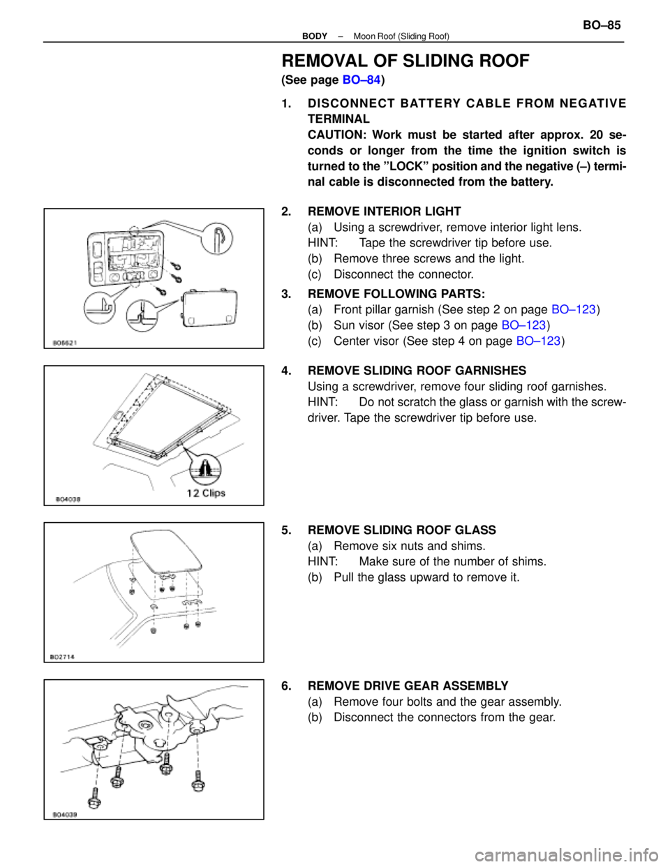
REMOVAL OF SLIDING ROOF
(See page BO±84)
1. DISCONNECT BATTERY CABLE FROM NEGATIVE TERMINAL
CAUTION: Work must be started after approx. 20 se-
conds or longer from the time the ignition switch is
turned to the ºLOCKº position and the negative (±) termi-
nal cable is disconnected from the battery.
2. REMOVE INTERIOR LIGHT (a) Using a screwdriver, remove interior light lens.
HINT: Tape the screwdriver tip before use.
(b) Remove three screws and the light.
(c) Disconnect the connector.
3. REMOVE FOLLOWING PARTS: (a) Front pillar garnish (See step 2 on page BO±123)
(b) Sun visor (See step 3 on page BO±123)
(c) Center visor (See step 4 on page BO±123)
4. REMOVE SLIDING ROOF GARNISHES Using a screwdriver, remove four sliding roof garnishes.
HINT: Do not scratch the glass or garnish with the screw-
driver. Tape the screwdriver tip before use.
5. REMOVE SLIDING ROOF GLASS (a) Remove six nuts and shims.
HINT: Make sure of the number of shims.
(b) Pull the glass upward to remove it.
6. REMOVE DRIVE GEAR ASSEMBLY (a) Remove four bolts and the gear assembly.
(b) Disconnect the connectors from the gear.
±
BODY Moon Roof (Sliding Roof)BO±85
WhereEverybodyKnowsYourName
Page 444 of 4087
6. ADJUST AND INSTALL DRIVE GEAR ASSEMBLY(a) Remove the screw and cam plate cover.
(b) Remove the large screw, washers and shims.
(c) Turn the drive shaft by screwdriver to align the housingand gear point mark as shown.
(d) Install cam plate cover with a screw.
(e) Install the drive gear assembly with four bolts.
(f) Connect the connectors.
7. INSTALL SLIDING GLASS HINT:
wConfirm that the lip part of the weatherstrip housing is
not twisted.
wConfirm that the clearance between the left and right of
the sliding roof glass and roof panel are equal.
Install six nuts and shims.
8. INSPECT SLIDING ROOF GLASS ALIGNMENT (See step 1 on page BO±81)
9. INSTALL FOLLOWING PARTS: (a) Sliding roof garnishes
(b) Roof headlining
(c) Sun visor
(d) Center visor
(e) Front pillar garnish
(f) Interior light
BO±88
±
BODY Moon Roof (Sliding Roof)
WhereEverybodyKnowsYourName
Page 445 of 4087

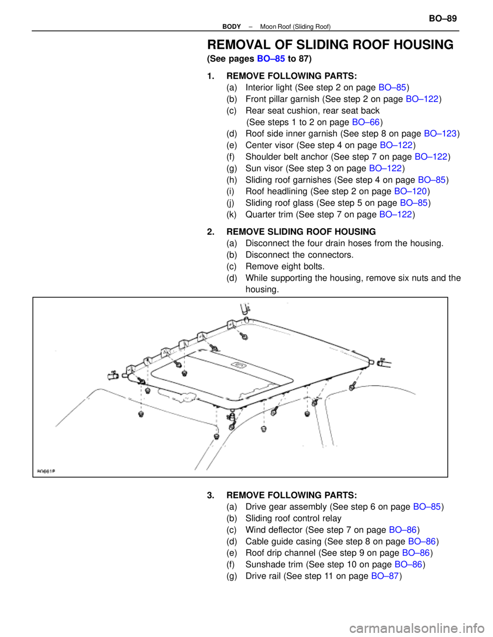
REMOVAL OF SLIDING ROOF HOUSING
(See pages BO±85 to 87)
1. REMOVE FOLLOWING PARTS: (a) Interior light (See step 2 on page BO±85)
(b) Front pillar garnish (See step 2 on page BO±122)
(c) Rear seat cushion, rear seat back (See steps 1 to 2 on page BO±66)
(d) Roof side inner garnish (See step 8 on page BO±123)
(e) Center visor (See step 4 on page BO±122)
(f) Shoulder belt anchor (See step 7 on page BO±122)
(g) Sun visor (See step 3 on page BO±122)
(h) Sliding roof garnishes (See step 4 on page BO±85)
(i) Roof headlining (See step 2 on page BO±120)
(j) Sliding roof glass (See step 5 on page BO±85)
(k) Quarter trim (See step 7 on page BO±122)
2. REMOVE SLIDING ROOF HOUSING (a) Disconnect the four drain hoses from the housing.
(b) Disconnect the connectors.
(c) Remove eight bolts.
(d) While supporting the housing, remove six nuts and thehousing.
3. REMOVE FOLLOWING PARTS: (a) Drive gear assembly (See step 6 on page BO±85)
(b) Sliding roof control relay
(c) Wind deflector (See step 7 on page BO±86)
(d) Cable guide casing (See step 8 on page BO±86)
(e) Roof drip channel (See step 9 on page BO±86)
(f) Sunshade trim (See step 10 on page BO±86)
(g) Drive rail (See step 11 on page BO±87)
±
BODY Moon Roof (Sliding Roof)BO±89
WhereEverybodyKnowsYourName
Page 475 of 4087
REMOVAL OF ROOF HEADLINING
(See page BO±119)
1. REMOVE FOLLOWING PARTS:
wFront pillar garnish
wSun visor
wRear seat back and cushion
wRoof side inner garnish
wQuarter trim
wInterior Light
wCenter visor
2. REMOVE ROOF HEADLINING (a) Disconnect four clips from the roof panel rear end.
(b) Using a clip remover, remove six clips.
(c) R e l e a s e t h e f a s t ener tapes, then remove the
headlining.
(d) Fully recline the front seat back.
(e) Bring out the headlining as shown.
NOTICE: Do not fold down the headlining.
INSTALLATION OF ROOF HEADLINING
(See page BO±119)
INSTALL ROOF HEADLINING PARTS BY FOLLOWING RE-
MOVAL SEQUENCE IN REVERSE HINT: Torque following parts:
(a) Rear seat back
Torque: 18 N Vm (185 kgf Vcm, 13 ft Vlbf)
(b) Rear seat belt inner belt
Torque: 43 N Vm (440 kgf Vcm, 32 ft Vlbf)
(c) Front seat belt shoulder anchor bolt
Torque: 43 N Vm (440 kgf Vcm, 32 ft Vlbf)
BO±120±
BODY Roof Headlining
WhereEverybodyKnowsYourName
Page 483 of 4087

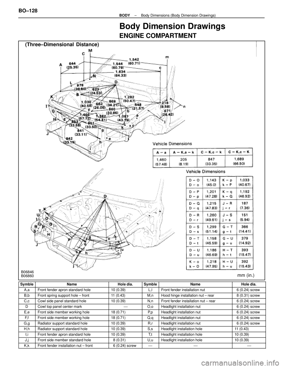
Body Dimension Drawings
ENGINE COMPARTMENT
(Three±Dimensional Distance)
mm (in.)B06846
B06860
Symble
NameHole dia.SymbleNameHole dia.
A,aFront fender apron standard hole10 (0.39)L,lFront fender installation nut6 (0.24) screw
B,bFront spring support hole ± front11 (0.43)M,nHood hinge installation nut ± rear8 (0.31) screw
C,cCowl side panel standard hole10 (0.39)N,nFront fender installation nut ± rear6 (0.24) screw
DCowl top panel center mark'O,oHeadlight installation nut6 (0.24) screw
E,eFront side member working hole18 (0.71)P, pHeadlight installation nut6 (0.24) screw
F, fFront side member working hole18 (0.71)Q,qHeadlight installation nut6 (0.24) screw
G,gRadiator support standard hole10 (0.39)R,rHeadlight installation nut6 (0.24) screw
H,hRadiator support standard hole10 (0.39)S,sHeadlight installation hole11 (0.43)
I,iFront fender apron standard hole10 (0.39)T, tHeadlight installation hole10 (0.39)
J,jFront side member standard hole8 (0.31)U,uHeadlight installation hole10 (0.39)
K,kFront fender installation nut ± front6 (0.24) screw'''
BO±128±
BODY Body Dimensions (Body Dimension Drawings)
WhereEverybodyKnowsYourName
Page 502 of 4087

SRS AIRBAG
(See page AB±2)
The LEXUS SC300 is equipped with an SRS (Supplemental Restraint System)\
airbag.
Failure to carry out service operations in the correct sequence could cause the airbag system to deploy,
possibly leading to a serious accident.
When removal or installation of airbag parts and the yellow wire harness\
and connector for the airbag is
necessary, refer to the precautionary notices in the AB section before performing\
the operation.
�Work must be started after 20 seconds or longer from the time the ignition switch is set to the LOCK
position and the negative (±) terminal cable is disconnected from the batte\
ry.
(The airbag system is equipped with a back±up power source so that if wor\
k is started within 20 se-
conds of disconnecting the negative (±) terminal cable of the batte\
ry, the airbag may be deployed.
�To avoid erasing the memory of each memory system, never use a back±up power supply from
outside the vehicle.
�Before repairs, remove the airbag sensors if shocks are likely to be applied t\
o the sensors during
repaires.
�The front airbag sensor set bolt has been anti±rust treated. When the\
sensor is removed, always
replace the set bolt with a new one.
�If the front airbag sensors, center airbag sensor or steering wheel pad ha\
ve been dropped, or if there
are cracks, dents or other defects in the case, bracket or connector, replace them with new ones.
�Never use airbag parts from another vehicle. When replacing parts, repla\
ce them with new parts.
�Do not expose the front airbag sensors, center airbag sensor or steering w\
heel pad directly to hot air
or flames.
�The airbag system's wire harness is integrated with the cowl wire harness assembly. The wires for the
airbag wire harness are encased in a yellow corrugated tube. All the connector\
s for the system are
also a standard yellow color. If the airbag system wire harness becomes disconnected or the
connector becomes broken due to an accident, etc., repair or replace it as shown \
on page AB±20.
�The steering wheel must be fitted correctly to the steering column with the\
spiral cable at the neutral
position; otherwise, cable disconnection and other troubles may result. \
Refer to page AB±14 of this
manual concerning correct steering wheel installation.
�When removing the steering wheel pad or handling a new steering wheel pad, i\
t should be placed with
the pad top surface facing up. In this case, the twin±lock type connector lock lever should be in the
locked state and care should be taken to place it so the connector will not be damaged. (\
Storing the
pad with its metallic surface up may lead to a serious accident if the a\
irbag inflates for some reason.)
�Grease should not be applied to the steering wheel pad and the pad should not \
be cleaned with
detergents of any kind.
�Store the steering wheel pad where the ambient temperature remains below 93 �C (200 �F), without
high humidity and away from electrical noise.
�Information labels are attached to the periphery of the airbag component\
s. Follow the notices.
�When the ignition switch is at ACC or ON and the airbag warning light remains on, the cent\
er airbag
sensor assembly has detected a malfunction code. (See page AB±30).
BO±8
±
BODY General Information
WhereEverybodyKnowsYourName
Page 506 of 4087
REMOVAL OF FRONT BUMPER
(See page BO±11)
1. REMOVE FENDER SPLASH SHIELD Remove fourteen screws, a bolt and the shield.
2. REMOVE NO. 2 ENGINE UNDER COVER Remove seven screws, five bolts and the cover.
3. REMOVE HEADLIGHT (Low Beam)
(a) Remove two nuts, a bolt and the headlight.
(b) Disconnect the connectors.
4. REMOVE UPPER BUMPER RETAINER (a) Remove the hood seal.
(b) Remove five screws and the retainer.
5. REMOVE BUMPER COVER ASSY (a) Remove six clips.
BO±12
±
BODY Bumper (Front Bumper)
WhereEverybodyKnowsYourName