Page 507 of 4087
(b) Remove four clips.
(c) Remove the clip and ambient temperature sensor.
(d) Remove four nuts.
(e) Remove ten clips.
(f) Remove two bolts.
(g) Disconnect the connectors.
(h) Remove the bumper cover assy.
6. REMOVE REINFORCEMENT Remove six bolts and the reinforcement.
7. REMOVE UPPER REINFORCEMENT Remove eight bolts and the reinforcement.
8. REMOVE HEADLIGHT (High Beam)
(a) Remove two screws, a clip and the headlight.
(b) Disconnect the connector.
±
BODY Bumper (Front Bumper)BO±13
WhereEverybodyKnowsYourName
Page 508 of 4087
INSTALLATION OF FRONT BUMPER
(See page BO±11)
INSTALL FRONT BUMPER PARTS BY FOLLOWING RE-
MOVAL SEQUENCE IN REVERSE HINT:
wWhen installing the bumper on the body, be careful
not to damage the serrated part of side bolts.
wAfter installing the headlight, adjust the light aiming.
(See page BE±38).
DISASSEMBLY AND ASSEMBLY OF
FRONT BUMPER
DISASSEMBLY AND ASSEMBLY BY
FOLLOWING PARTS:
(a) Cornering lights
(b) Side turn lights
(c) Bumper energy absorber
(d) Retainers
(e) License bracket
BO±14
±
BODY Bumper (Front Bumper)
WhereEverybodyKnowsYourName
Page 510 of 4087
REMOVAL OF REAR BUMPER
(See page BO±15)
1. REMOVE FOLLOWING PARTS:
(See steps 1 to 6 on pages BO±79 to 80)
(a) Floor mat
(b) Door striker cover
(c) Trim rear cover
(d) Trim front cover
(e) LH side cover
(f) RH side cover
2. REMOVE REAR COMBINATION LIGHT (a) Remove four nuts and disconnect the connectors.
(b) Remove the light.
3. REMOVE VENTILATION DUCT Remove three screws and the duct.
4. REMOVE REAR BUMPER COVER
(a) Remove sixteen clips and six nuts.
(b) Remove the cover.
BO±16±
BODY Bumper (Rear Bumper)
WhereEverybodyKnowsYourName
Page 511 of 4087
5. REMOVE LICENCE LIGHT AND BUMPER EXTENSION(a) Remove the bumper energy absorber from the bumpercover.
(b) Remove three screws and the light.
(c) Remove the nut and the extension.
6. REMOVE BUMPER REINFORCEMENT Remove six bolts and the reinforcement.
INSTALLATION OF REAR BUMPER
(See page BO±15)
INSTALL REAR BUMPER PARTS BY FOLLOWING
REMOVAL SEQUENCE IN REVERSE
±
BODY Bumper (Rear Bumper)BO±17
WhereEverybodyKnowsYourName
Page 525 of 4087
2. ADJUST FRONT DOOR IN LEFT/RIGHT AND VERTICALDIRECTIONS
Loosen the door side hinge bolts to adjust.
3. ADJUST FRONT DOOR LOCK STRIKER (a) Check that the door fit and door lock link ages are
adjusted correctly.
(b) Using a screwdriver, remove the striker cover.
HINT: Tape the screwdriver tip before use.
(c) Adjust the striker position by slightly loosening the striker mounting screws, and hitting the striker with a
hammer. Tighten the striker mounting screws again.
(d) Install the striker cover.
BO±30
±
BODY Front Door (Fitting Adjustments)
WhereEverybodyKnowsYourName
Page 528 of 4087
DISASSEMBLY OF FRONT DOOR
(See page BO±31)
1. REMOVE ARMREST BASE PANEL (a) Using the screwdriver, remove the clip.
(b) Pull the panel forward and disconnect the connector.
2. REMOVE DOOR INSIDE HANDLE BEZEL COVER Using the small screwdriver, pry outward the cover.
3. REMOVE DOOR TRIM (a) Remove two caps and eight screws.
(b) Insert the screwdriver between the panel and the trimand remove clips.
HINT: Do not scratch the panel with the screwdriver.
(c) Remove the trim by pulling all of the trim.
(d) Remove the two cables from the door inside handle.
(e) Disconnect the connector from the door curtesy light.
±
BODY Front DoorBO±33
WhereEverybodyKnowsYourName
Page 529 of 4087
(f) Remove twelve nuts, the front door trim ornament andthe door inside handle.
(g) Remove eight screws and armrest.
(h) Remove the door courtesy light.
4. REMOVE DOOR SPEAKER GRILLE Using a screwdriver, pry loose two clips and remove the cov-
er.
HINT: Tape the screwdriver tip before use.
5. REMOVE DOOR TRIM UPPER PANEL Remove six screws and pry out the panel.
6. REMOVE FRONT DOOR WEATHERSTRIP While pulling the weatherstrip by hand, remove the nine clips
using a clip remover.
HINT: Do not pull strongly on the weatherstrip as it may
tear.
7. REMOVE OUTSIDE REAR VIEW MIRROR AND SPEAKER
(a) Remove two bolts and the speaker, disconnect the connector.
(b) Remove two bolts and the mirror, disconnect the connector.
BO±34
±
BODY Front Door
WhereEverybodyKnowsYourName
Page 537 of 4087

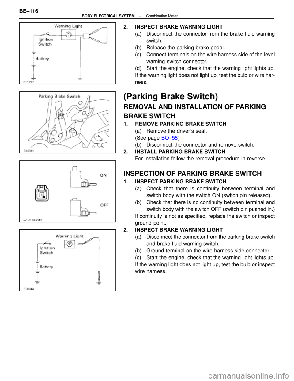
2. INSPECT BRAKE WARNING LIGHT(a) Disconnect the connector from the brake fluid warningswitch.
(b) Release the parking brake pedal.
(c) Connect terminals on the wire harness side of the level warning switch connector.
(d) Start the engine, check that the warning light lights up.
If the warning light does not light up, test the bulb or wire har-
ness.
(Parking Brake Switch)
REMOVAL AND INSTALLATION OF PARKING
BRAKE SWITCH
1. REMOVE PARKING BRAKE SWITCH
(a) Remove the driver's seat.
(See page BO±58)
(b) Disconnect the connector and remove switch.
2. INSTALL PARKING BRAKE SWITCH For installation follow the removal procedure in reverse.
INSPECTION OF PARKING BRAKE SWITCH
1. INSPECT PARKING BRAKE SWITCH
(a) Check that there is continuity between terminal andswitch body with the switch ON (switch pin released).
(b) Check that there is no continuity between terminal and switch body with the switch OFF (switch pin pushed in.)
If continuity is not as specified, replace the switch or inspect
ground point.
2. INSPECT BRAKE WARNING LIGHT (a) Disconnect the connector from the parking brake switchand brake fluid warning switch.
(b) Ground terminal on the wire harness side connector.
(c) Start the engine, check that the warning light lights up.
If the warning light does not light up, test the bulb or inspect
wire harness.
BE±116
±
BODY ELECTRICAL SYSTEM Combination Meter
WhereEverybodyKnowsYourName