Page 455 of 4087
Back Window Moulding
COMPONENTS
REMOVAL AND INSTALLATION OF
BACK WINDOW LOWER MOULDING
1. REMOVE LOWER MOULDINGUsing the scraper, pry off the moulding from the six clips and
remove the moulding.
HINT: Tape the scraper tip before use.
2. IF NECESSARY, REPLACE LOWER MOULDING CLIPS HINT: There are two types of clips for moulding installa-
tion.
Location of these clips is as shown.
±
BODY Moulding (Back Window Moulding)BO±99
WhereEverybodyKnowsYourName
Page 456 of 4087
3. INSTALL LOWER MOULDING(a) Place the moulding onto the body.
(b) Tap the moulding by your hand to install the moulding.
REMOVAL AND INSTALLATION OF
BACK WINDOW OUTSIDE MOULDING
1. REMOVE BACK WINDOW GLASS(See page BO±54)
2. REMOVE OUTSIDE MOULDING Using a knife, cut loose the moulding around the glass.
3. CLEAN CONTACT SURFACE OF GLASS Using a cleaner, clean the contact surface black±colored
area.
NOTICE: Do not touch the glass face after cleaning it.
4. INSTALL OUTSIDE MOULDING (a) Coat the edge of the glass with primer.
(b) Coat the moulding with adhesive on all contact surfaces.
(c) Install the moulding.
(d) Use a scraper to remove any excess or protruding adhesive.
5. INSTALL BACK WINDOW GLASS
6. INSTALL LOWER MOULDING
BO±100
±
BODY Moulding (Back Window Moulding)
WhereEverybodyKnowsYourName
Page 458 of 4087

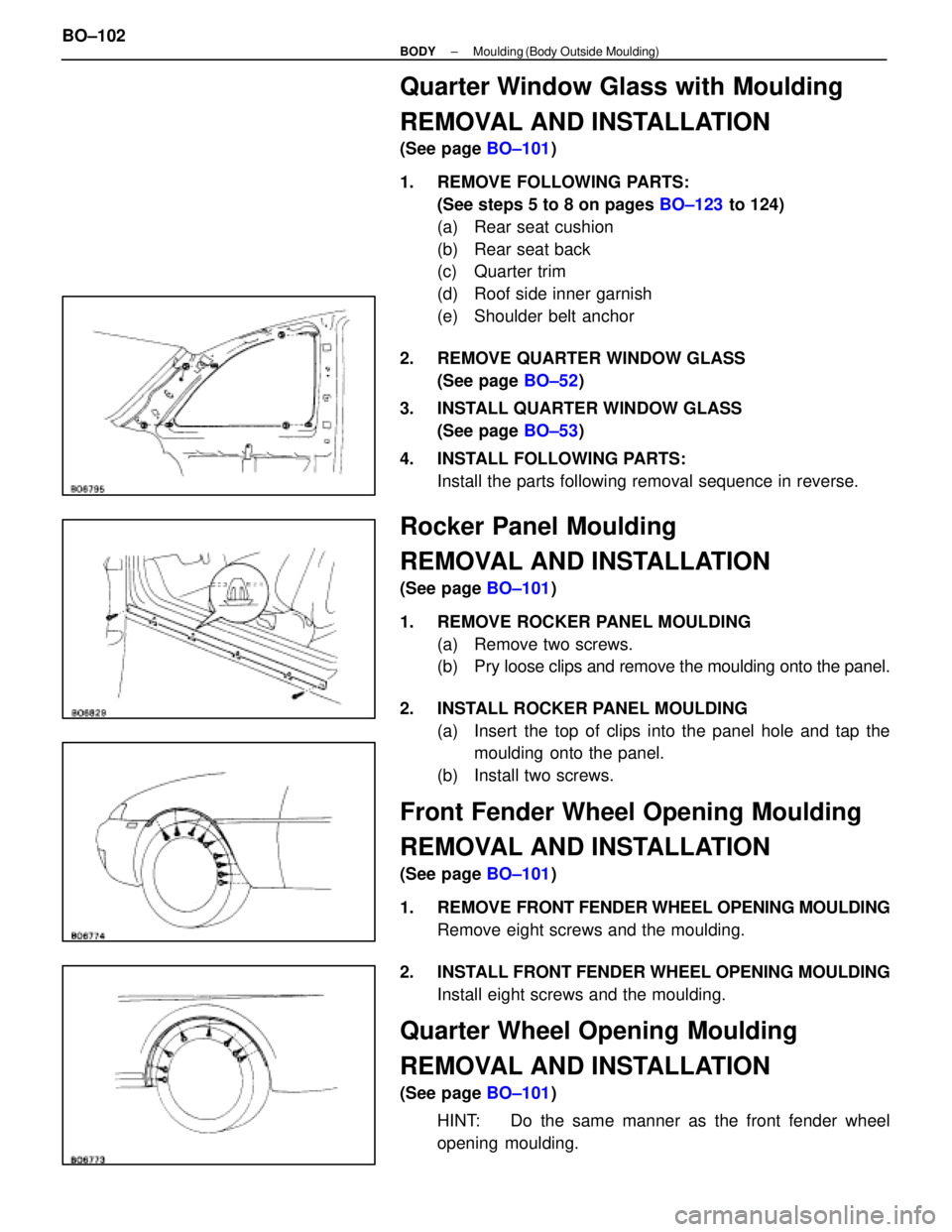
Quarter Window Glass with Moulding
REMOVAL AND INSTALLATION
(See page BO±101)
1. REMOVE FOLLOWING PARTS: (See steps 5 to 8 on pages BO±123 to 124)
(a) Rear seat cushion
(b) Rear seat back
(c) Quarter trim
(d) Roof side inner garnish
(e) Shoulder belt anchor
2. REMOVE QUARTER WINDOW GLASS (See page BO±52)
3. INSTALL QUARTER WINDOW GLASS (See page BO±53)
4. INSTALL FOLLOWING PARTS: Install the parts following removal sequence in reverse.
Rocker Panel Moulding
REMOVAL AND INSTALLATION
(See page BO±101)
1. REMOVE ROCKER PANEL MOULDING (a) Remove two screws.
(b) Pry l oose clips and remove the moulding onto the panel.
2. INSTALL ROCKER PANEL MOULDING (a) Insert the top of clips into the panel hole and tap themoulding onto the panel.
(b) Install two screws.
Front Fender Wheel Opening Moulding
REMOVAL AND INSTALLATION
(See page BO±101)
1. REMOVE FRONT FENDER WHEEL OPENING MOULDING
Remove eight screws and the moulding.
2. INSTALL FRONT FENDER WHEEL OPENING MOULDING Install eight screws and the moulding.
Quarter Wheel Opening Moulding
REMOVAL AND INSTALLATION
(See page BO±101)
HINT: Do the same manner as the front fender wheel
opening moulding.
BO±102
±
BODY Moulding (Body Outside Moulding)
WhereEverybodyKnowsYourName
Page 515 of 4087
DISASSEMBLY OF HOOD
(See page BO±19)
1. REMOVE HOOD AUXILIARY CATCH HOOK
2. REMOVE HOOD TO RADIATOR SUPPORT SEAL Using a clip remover, remove clips and the seal.
3. REMOVE HOOD INSULATOR Using a clip remover, remove clips and the insulator.
4. REMOVE HOOD CUSHION Turn the cushions counter clockwise with your hand to re-
move it.
5. REMOVE WINDOW WASHER HOSE
6. REMOVE WINDOW WASHER NOZZLE (a) Remove the cover.
(b) Using a screwdriver, remove the nozzle.
HINT: Tape the screwdriver tip before use.
ASSEMBLY OF HOOD
(See page BO±19)
ASSEMBLE HOOD PARTS BY FOLLOWING DISASSEMBLY
SEQUENCE IN REVERSE
±
BODY HoodBO±21
WhereEverybodyKnowsYourName
Page 531 of 4087
14. REMOVE FRONT DOOR INNER WEATHERSTRIPPry loose the clips from the edge of the panel and remove the
belt moulding.
15. REMOVE FRONT GLASS GUIDE Remove three screws and the guide.
16. REMOVE REAR GLASS GUIDE AND DOOR GLASS (a) Remove four screws from the guide.
(b) Remove joining the window regulator and glass.
(c) Pull the door glass with the guide out of the panel carefully.
HINT: Do not remove the guide from the glass.
17. REMOVE WINDOW REGULATOR Remove six nuts and the regulator.
18. REMOVE DOOR LOCK (a) Disconnect the two links from the outside handle andkey cylinder.
(b) Disconnect the connector.
(c) Using a trox rench, remove three screws and the door lock.
BO±36
±
BODY Front Door
WhereEverybodyKnowsYourName
Page 533 of 4087

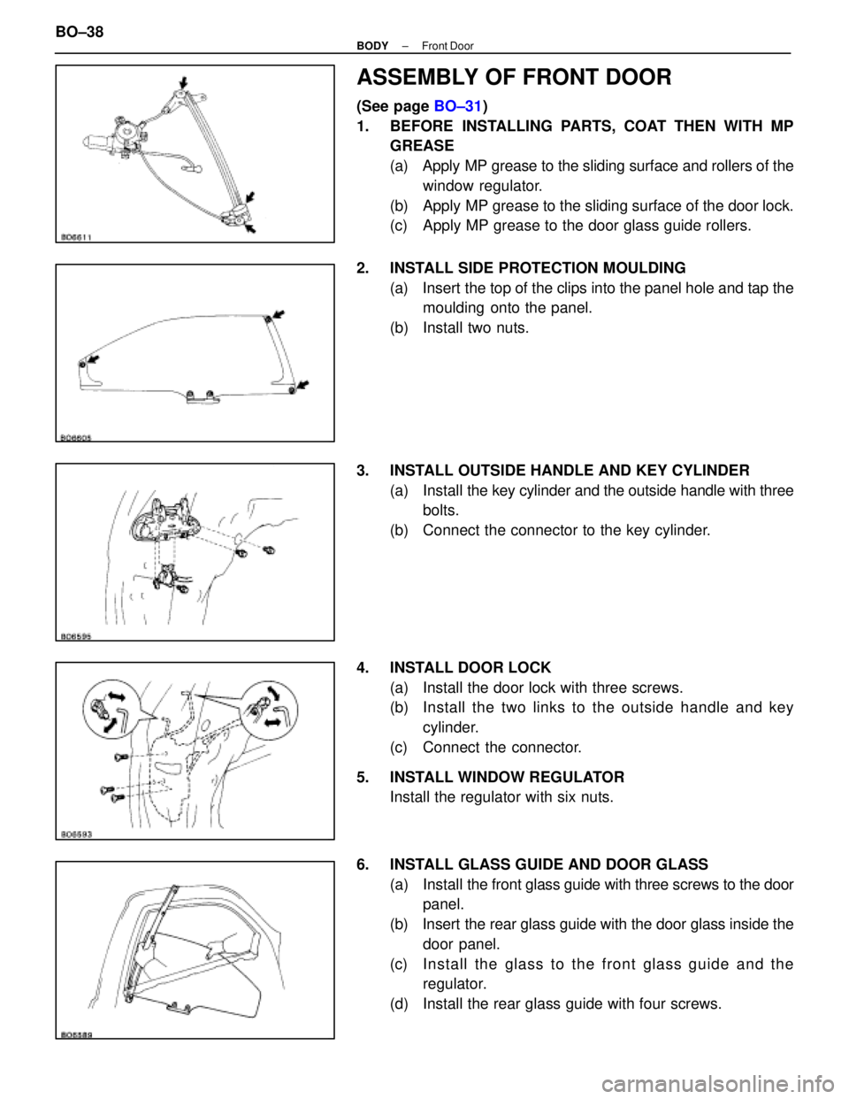
ASSEMBLY OF FRONT DOOR
(See page BO±31)
1. BEFORE INSTALLING PARTS, COAT THEN WITH MP GREASE
(a) Apply MP grease to the sliding surface and rollers of the
window regulator.
(b) Apply MP grease to the sliding surface of the door lock.
(c) Apply MP grease to the door glass guide rollers.
2. INSTALL SIDE PROTECTION MOULDING (a) Insert the top of the clips into the panel hole and tap themoulding onto the panel.
(b) Install two nuts.
3. INSTALL OUTSIDE HANDLE AND KEY CYLINDER (a) Install the key cylinder and the outside handle with three
bolts.
(b) Connect the connector to the key cylinder.
4. INSTALL DOOR LOCK (a) Install the door lock with three screws.
(b) Install the two links to the outside h andle and key
cylinder.
(c) Connect the connector.
5. INSTALL WINDOW REGULATOR Install the regulator with six nuts.
6. INSTALL GLASS GUIDE AND DOOR GLASS (a) Install the front glass guide with three screws to the door
panel.
(b) Insert the rear glass guide with the door glass inside the door panel.
(c) In sta ll th e gla ss to th e fro n t gla ss gu id e an d th e regulator.
(d) Install the rear glass guide with four screws.
BO±38
±
BODY Front Door
WhereEverybodyKnowsYourName
Page 539 of 4087

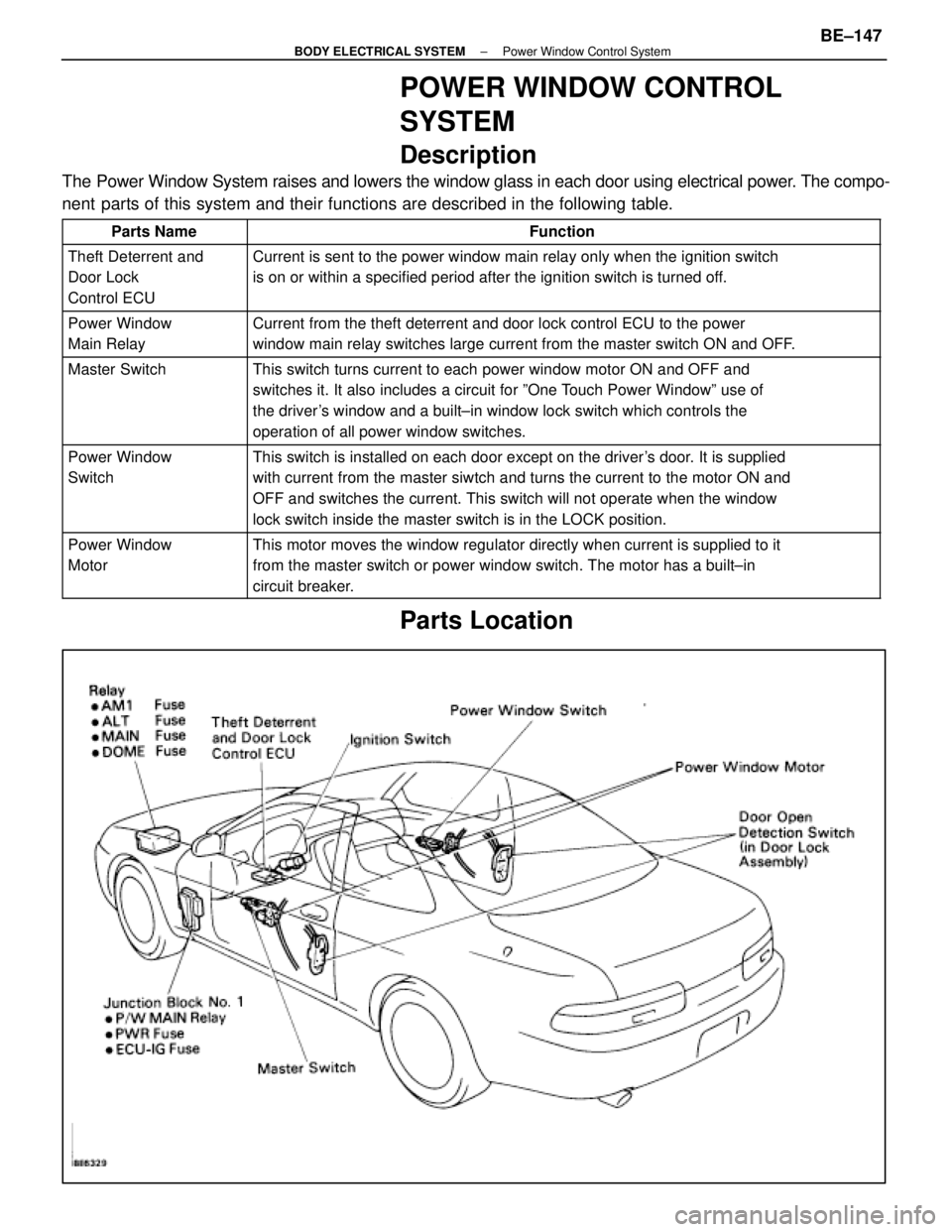
POWER WINDOW CONTROL
SYSTEM
Description
The Power Window System raises and lowers the window glass in each door usi\
ng electrical power. The compo-
nent parts of this system and their functions are described in the following\
table.
Parts NameFunction
Theft Deterrent and
Door Lock
Control ECUCurrent is sent to the power window main relay only when the ignition sw\
itch
is on or within a specified period after the ignition switch is turned o\
ff.
Power Window
Main RelayCurrent from the theft deterrent and door lock control ECU to the power
window main relay switches large current from the master switch ON and O\
FF.
Master SwitchThis switch turns current to each power window motor ON and OFF and
switches it. It also includes a circuit for ºOne Touch Power Windowº use of
the driver's window and a built±in window lock switch which controls the
operation of all power window switches.
Power Window
SwitchThis switch is installed on each door except on the driver's door. It is supplied
with current from the master siwtch and turns the current to the motor O\
N and
OFF and switches the current. This switch will not operate when the wind\
ow
lock switch inside the master switch is in the LOCK position.
Power Window
MotorThis motor moves the window regulator directly when current is supplied \
to it
from the master switch or power window switch. The motor has a built±\
in
circuit breaker.
Parts Location
±
BODY ELECTRICAL SYSTEM Power Window Control SystemBE±147
WhereEverybodyKnowsYourName
Page 540 of 4087
Wiring and Connector Diagrams
BE±148±
BODY ELECTRICAL SYSTEM Power Window Control System
WhereEverybodyKnowsYourName