Page 764 of 4087
DESCRIPTION
The wireless door lock control system is to lock and unlock all the door\
s at a distance, transmitting a weak radio
wave from a transmitter contained in the master ignition key.
The weak radio wave (coded differently for each key) is sent to the receiver via the rear window defo\
gger wiring.
For the function of the component parts of this system, refer to the circui\
t description in circuit inspection.
PARTS LOCATION
BE±440±
BODY ELECTRICAL SYSTEM Wireless Door Lock Control System
WhereEverybodyKnowsYourName
Page 769 of 4087

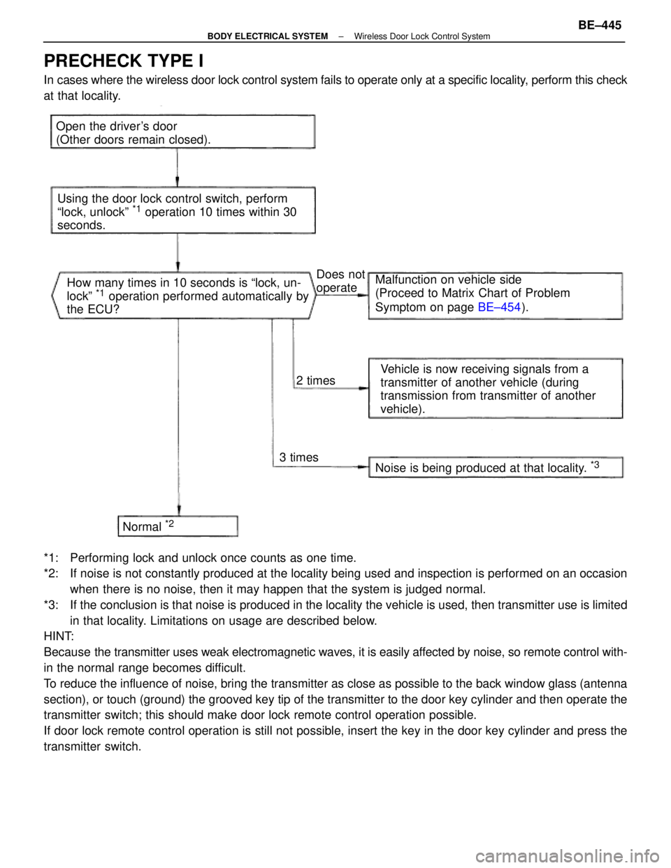
PRECHECK TYPE I
In cases where the wireless door lock control system fails to operate only\
at a specific locality, perform this check
at that locality.
Open the driver's door
(Other doors remain closed).Using the door lock control switch, perform
ªlock, unlockº
*1 operation 10 times within 30
seconds.
How many times in 10 seconds is ªlock, un-
lockº
*1 operation performed automatically by
the ECU?
Noise is being produced at that locality.
*3
Vehicle is now receiving signals from a
transmitter of another vehicle (during
transmission from transmitter of another
vehicle).
Malfunction on vehicle side
(Proceed to Matrix Chart of Problem
Symptom on page
BE±454).
Does not
operate
2 times
3 times
Normal
*2
*1: Performing lock and unlock once counts as one time.
*2: If noise is not constantly produced at the locality being used and inspect\
ion is performed on an occasion when there is no noise, then it may happen that the system is judged normal.\
*3: If the conclusion is that noise is produced in the locality the vehicle is\
used, then transmitter use is limited in that locality. Limitations on usage are described below.
HINT:
Because the transmitter uses weak electromagnetic waves, it is easily affected by noise, so remote control with-
in the normal range becomes difficult.
To reduce the influence of noise, bring the transmitter as close as possib\
le to the back window glass (antenna
section), or touch (ground) the grooved key tip of the transmitter to\
the door key cylinder and then operate the
transmitter switch; this should make door lock remote control operation possible.
If door lock remote control operation is still not possible, insert the \
key in the door key cylinder and press the
transmitter switch.
±
BODY ELECTRICAL SYSTEM Wireless Door Lock Control SystemBE±445
WhereEverybodyKnowsYourName
Page 804 of 4087
PREPARATION
SST (SPECIAL SERVICE TOOLS)
IllustrationPart No.Part NameNote
09213±31021
Crankshaft Pulley
Puller
For removing steering wheel
RECOMMENDED TOOLS
IllustrationPart No.Part NameNote
09082±00015TOYOTA
Electrical Tester
09041±0030Torx Driver
T30
For removing and installing steering wheel pad and
power window motor
09042±00010Torx Socket
T30For removing and installing steering wheel pad and
power window motor
EQUIPMENT
Part NameNote
Voltmeter
Ammeter
Ohmmeter
Test lead
ThermometerWater temperature sender gauge, Engine oil level, Warning switch, Seat heater
SyphonBrake fluid level warning switch
Oil bathEngine oil level warning switch
Bulb (1.4 W)Coolant level warning ECU
Bulb (3.4 W)Fuel sender, gauge, Seat belt warning relay
Bulb (21 W)Turn signal flasher relay
Dry cell batteryFuel sender gauge
Heat lightSeat heater
Hexagon wrench (6 mm)Power seat
BE±8±
BODY ELECTRICAL SYSTEM Preparation
WhereEverybodyKnowsYourName
Page 805 of 4087
EQUIPMENT (Cont'd)
PartNote
Torque wrench
Clip removerFor removing cowl louver
Masking tapeRear window defogger wire
Tim foilRear window defogger wire
SSM (SPECIAL SERVICE MATERIALS)
Part NamePart No.Use etc.
Adhesive 1324,
Three bond 1324 or equivalent08833±00070Power seat housing set nut, Power seat slide and vertical
motor set screw
Adhesive 1344,
Three bond 1344,
Loctite 242 or equivalent
08833±00080Low oil pressure warning switch Water temperature
sender gauge
Dupont paste No. 4817±Rear window defogger wire
±
BODY ELECTRICAL SYSTEM PreparationBE±9
WhereEverybodyKnowsYourName
Page 814 of 4087

Description
The power source supplies power to each of the vehicle's electrical devices. It is composed of the battery, fuses
and relays, which are located centrally at relay block No. 2 and relay block No. 6 i\
n the engine compartment
and junction block No. 1 relay block No. 4 and relay block No. 5 in the \
cabin near the driver's feet.
Related systems for each Fuse
No.Part NameRelated Systems or Parts
1IGN � Charging System � AIR±BAG System1IGN � Engine
2ST � Starter
3WIPER � Wiper and Washer System
4HTR � Defogger System � A/C System
5ENGINE � Charging System
6RADIO NO. 2 � Audio System � Power Mirror System
� Cigarette Lighter � A/C System
7CIG � Combination Meter System � AIR±BAG System7CIG � Shift Lock System � Theft Deterrent System
� TEL System
8STOP � Stop Light System � Cruise Control System
9TURN � Turn Signal and Hazard
Warning Light System � Cornnering Light System
10MIR HTR � Mirror Heater System
11PANEL � Illumination Light System
12ECU±B � Combination Meter System � AIR±BAG System
� Combination Meter System � ECT System
13GAUGE � Back±Up Light � Transmission Indicator
� Light Failare Sensor � ABS and TRAC
� Power Seat System � Door Lock Control System
� TEL System � Shift Lock System
14ECU±IG � Radiator Fan � Auto Antenna
� Electric Tension Reducer System � Power Steering
� Auto±Tilt away Steering � Cruise Control System
15TAIL � Taillight System � Side Marker15TAIL � Clearance Light
16DOOR � Power Seat System � Luggage Door Opener16DOOR � Door Lock Control System � Fuel Lid Opener System
17IG SWUpstream of ECU±IG, ENGINE, WIP, HTR, TURN, GAUGE, and ST Fuse
18PWR � Power Window System � Sliding Roof System
19ABS NO. 1 � ABS and TRAC
20AM1Upstream of MIR HTR, TAIL, PANEL, STOP, ECUA±B, DOOR and PWR Fuse
21ALTUpstream of DEF, HTR, AM1, and ABS No. 1 Fuse
BE±18±
BODY ELECTRICAL SYSTEM Power Source
WhereEverybodyKnowsYourName
Page 847 of 4087

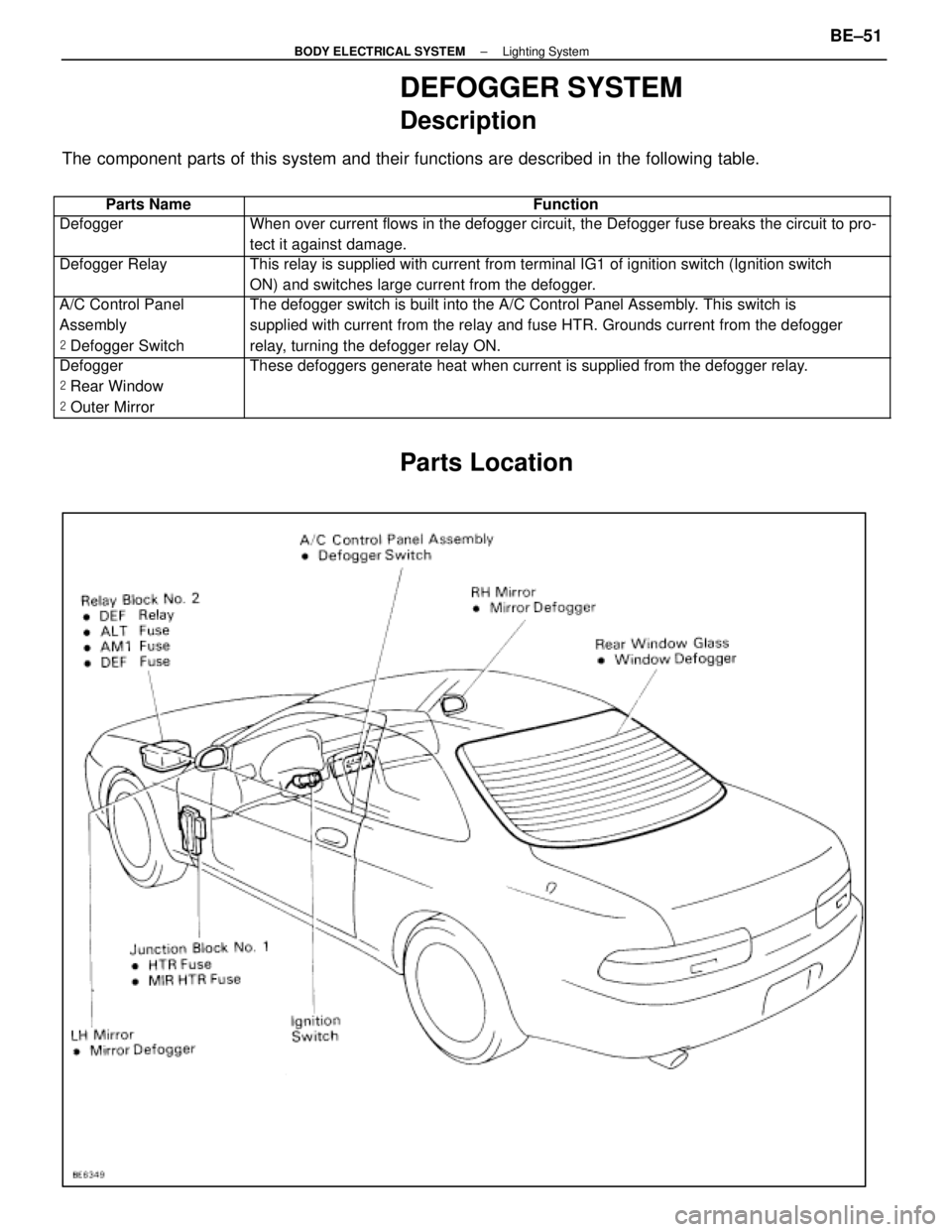
DEFOGGER SYSTEM
Description
The component parts of this system and their functions are described in the\
following table.
��������� ���������Parts Name������������������\
���������� ������������������\
����������Function
��������� ���������Defogger������������������\
���������� ������������������\
����������When over current flows in the defogger circuit, the Defogger fuse break\
s the circuit to pro-
tect it against damage.
��������� �
��������
���������
Defogger Relay������������������\
���������� �
������������������\
���������
������������������\
����������
This relay is supplied with current from terminal IG1 of ignition switch\
(Ignition switch
ON) and switches large current from the defogger.
��������� �
��������
���������
A/C Control Panel
Assembly
�
Defogger Switch������������������\
���������� �
������������������\
���������
������������������\
����������
The defogger switch is built into the A/C Control Panel Assembly. This switch is
supplied with current from the relay and fuse HTR. Grounds current from \
the defogger
relay, turning the defogger relay ON.
��������� �
��������
�
��������
���������
Defogger
�
Rear Window
� Outer Mirror������������������\
���������� �
������������������\
���������
�
������������������\
���������
������������������\
����������
These defoggers generate heat when current is supplied from the defogger\
relay.
Parts Location
±
BODY ELECTRICAL SYSTEM Lighting SystemBE±51
WhereEverybodyKnowsYourName
Page 891 of 4087

Check forTester connectionConditionSpecified value
VoltageA14±GroundIgnition switchpositionLOCK or ACCNo voltageA14±GroundIgnition switch positionONBattery positive voltage
ContinuityA6±GroundConstantContinuity
(Washer Motor and Tank)
REMOVAL AND INSTALLATION OF
WASHER MOTOR AND TANK
1. REMOVE WASHER TANK AND WASHER MOTOR(a) Remove fender liner.
(b) Disconnect connector and hose.
(c) Remove three screws and tank.
(d) Separate tank and washer motor.
2. INSTALL WASHER TANK AND MOTOR For installation follow the removal procedure in reverse.
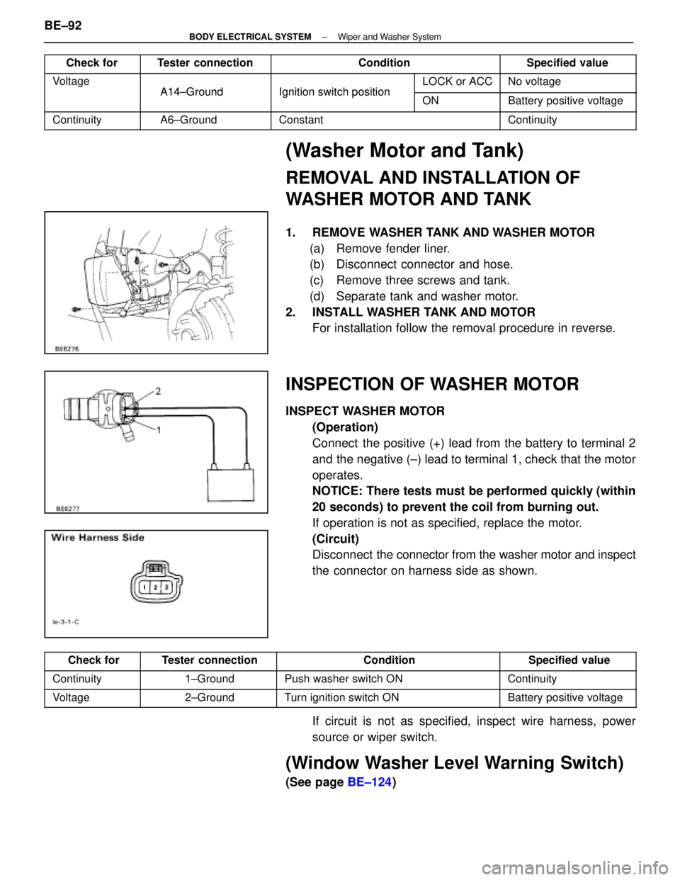
INSPECTION OF WASHER MOTOR
INSPECT WASHER MOTOR
(Operation)
Connect the positive (+) lead from the battery to terminal 2
and the negative (±) lead to terminal 1, check that the motor
operates.
NOTICE: There tests must be performed quickly (within
20 seconds) to prevent the coil from burning out.
If operation is not as specified, replace the motor.
(Circuit)
Disconnect the connector from the washer motor and inspect
the connector on harness side as shown.
Check forTester connectionConditionSpecified value
Continuity1±GroundPush washer switch ONContinuity
Voltage2±GroundTurn ignition switch ONBattery positive voltage
If circuit is not as specified, inspect wire harness, power
source or wiper switch.
(Window Washer Level Warning Switch)
(See page BE±124)
BE±92
±
BODY ELECTRICAL SYSTEM Wiper and Washer System
WhereEverybodyKnowsYourName
Page 893 of 4087

TROUBLESHOOTING
You will find the cause of trouble more easily by properly using the table \
shown below. In this table, the num-
bers indicate the order priority of causes of trouble. Check each part in th\
e order shown. If necessary, re-
place the parts.
See pageB±4,21BE±26BE±4,20BE±91BE±90BE±92BE±91BE±93±
Trouble
Part Name
AM1 FuseIgnition SwitchWIPER FuseWiper SwitchWiper MotorWasher MotorWasher SwitchWasher Hose and NozzleWire Harness
Wipers and washers do not operate.*1132456
Wipers and washers do not operate.*221345
Wipers and washers do not operate.*31234
Wipers do not operate in LO, HI or MIST.123
Wipers do not operate in INT.123
Washer motor does not operate.213
Wipers do not operate when washer switch
is ON.12
Washer fluid does not spray.1
*1: Door Lock and Power Windows do not operate
*
2: Door Lock and Power Window are normal. Combination Meter and Turn Signal do not operate.
*
3: Combination Meter and Turn Signal are normal.
BE±94
±
BODY ELECTRICAL SYSTEM Wiper and Washer System
WhereEverybodyKnowsYourName