Page 549 of 4087

Troubleshooting
You will find the cause of trouble more easily by properly using the table \
shown below. In this table, the
numbers indicate the order of priority of the causes of trouble. Check each part in \
the order shown. If neces-
sary, replace the part.
See page
BE±4 ,21BE±4,21BE±4,20BE±4,20BE±156BE±152BE±149BE±151BE±152BE±26BE±392BE±4,20 ±±
Part
name
Trouble
AM1 FuseDOME FuseDOOR FusePOWER FuseTheft Deterrent and Door Lock Control ECUPower Window Main RelayPower Window Master SwitchPower Window SwitchPower Window MotorIgnition SwitchDoor Open Detection SwitchECU±IG FuseWire Harness
*1 Power window does not operate.1234
*2 Power window does not operate.35467218
ªOne Touch Power Window Systemº does
not operate.1
Only one window glass does not move.1234
ªWindow Lock Systemº does not operate1
ªWindow Lock Illuminationº does not light
up.1
Key±off power window does not operate124536
*1: Dook Lock does not operate.
*2: Dook Lock is normal.
±
BODY ELECTRICAL SYSTEM Power Window Control SystemBE±157
WhereEverybodyKnowsYourName
Page 557 of 4087
DEFOGGER SYSTEM
Description
The component parts of this system and their functions are described in the\
following table.
Parts NameFunction
DefoggerWhen over current flows in the defogger circuit, the Defogger fuse break\
s the circuit
to protect it against damage.
Defogger RelayThis relay is supplied with current from terminal IG1 of ignition switch\
(Ignition switch ON)
and switches large current from the defogger.
A/C Control Panel
Assembly
� Defogger SwitchThe defogger switch is built into the A/C Control Panel Assembly. This switch is
supplied with current from the relay and fuse HTR. Grounds current from \
the defogger
relay, turning the defogger relay ON.
Defogger
� Rear Window
� Outer MirrorThese defoggers generate heat when current is supplied from the defogger\
relay.
Parts Location
±
BODY ELECTRICAL SYSTEM Defogger SystemBE±171
WhereEverybodyKnowsYourName
Page 561 of 4087
INSPECTION OF MIRROR DEFOGGER
INSPECT MIRROR DEFOGGER(a) Connect the positive (+) lead from the battery to terminal
7 and the negative (±) lead to terminal 8.
(b) Check that the mirror becomes warm.
HINT: It will take a short time for the mirror to become warm.
If the mirror does not become warm, replace the mirror as-
sembly.
Troubleshooting
You will find the cause of trouble more easily using the table shown below. In this table, the number indicate
the order priority of the causes in trouble. Check each part in the order s\
hown. If necessary, replace the parts.
See pageBE±4 ,20BE±4,20BE±4,22BE±172BE±173 ±±BE±173 ±±BE±174
TroubleParts
name
HEATER FuseMIR±HTR FuseDEFOG FuseDefogger SwitchDefogger RelayWire HarnessDefogger WiresCKE CoilMirror Defogger
All defogger systems do not operate.11234
Rear window defogger does not operate.312
Mirror Defogger does not operate.132
±
BODY ELECTRICAL SYSTEM Defogger SystemBE±175
WhereEverybodyKnowsYourName
Page 562 of 4087

SLIDING ROOF SYSTEM
Description
Standby Operation
� Current flows from the DOME fuse to terminal A1 of the sliding roof control rel\
ay (hereafter called
relay).
� When the ignition switch is ON, the current flows from the power window relay to terminal A3 of the
relay.
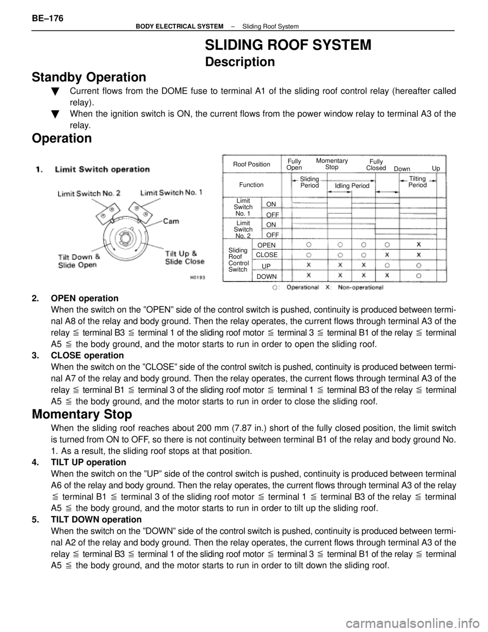
Operation
Roof Position
Function Fully
Open Fully
Closed
Momentary
Stop
Limit
Switch
No. 1
Limit
Switch
No. 2
Sliding
Roof
Control
Switch Down
Up
Sliding Period Idling Period
CLOSE DOWN OPEN
UP ON
ON OFF
OFF
Tilting
Period
2. OPEN operation
When the switch on the ºOPENº side of the control switch is pushed, co\
ntinuity is produced between termi-
nal A8 of the relay and body ground. Then the relay operates, the curren\
t flows through terminal A3 of the
relay � terminal B3 � terminal 1 of the sliding roof motor � terminal 3 � terminal B1 of the relay � terminal
A5 � the body ground, and the motor starts to run in order to open the slidi\
ng roof.
3. CLOSE operation
When the switch on the ºCLOSEº side of the control switch is pushed, c\
ontinuity is produced between termi-
nal A7 of the relay and body ground. Then the relay operates, the current f\
lows through terminal A3 of the
relay � terminal B1 � terminal 3 of the sliding roof motor � terminal 1 � terminal B3 of the relay � terminal
A5 � the body ground, and the motor starts to run in order to close the slid\
ing roof.
Momentary Stop
When the sliding roof reaches about 200 mm (7.87 in.) short of the fully closed position, the limit \
switch
is turned from ON to OFF, so there is not continuity between terminal B1 of the relay and body g\
round No.
1. As a result, the sliding roof stops at that position.
4. TILT UP operation
When the switch on the ºUPº side of the control switch is pushed, cont\
inuity is produced between terminal
A6 of the relay and body ground. Then the relay operates, the current flow\
s through terminal A3 of the relay
� terminal B1 � terminal 3 of the sliding roof motor � terminal 1 � terminal B3 of the relay � terminal
A5 � the body ground, and the motor starts to run in order to tilt up the sl\
iding roof.
5. TILT DOWN operation When the switch on the ºDOWNº side of the control switch is pushed, co\
ntinuity is produced between termi-
nal A2 of the relay and body ground. Then the relay operates, the current f\
lows through terminal A3 of the
relay � terminal B3 � terminal 1 of the sliding roof motor � terminal 3 � terminal B1 of the relay � terminal
A5 � the body ground, and the motor starts to run in order to tilt down the \
sliding roof.
BE±176
±
BODY ELECTRICAL SYSTEM Sliding Roof System
WhereEverybodyKnowsYourName
Page 565 of 4087

Parts Inspection
(Power Window Main Relay)
INSPECTION OF POWER WINDOW MAIN
RELAY
(See Power Window Main Relay on page BE±152)
(Sliding Roof Switch)
REMOVAL AND INSTALLATION OF
SLIDING ROOF SWITCH
(See Sliding Roof on page BO±85)
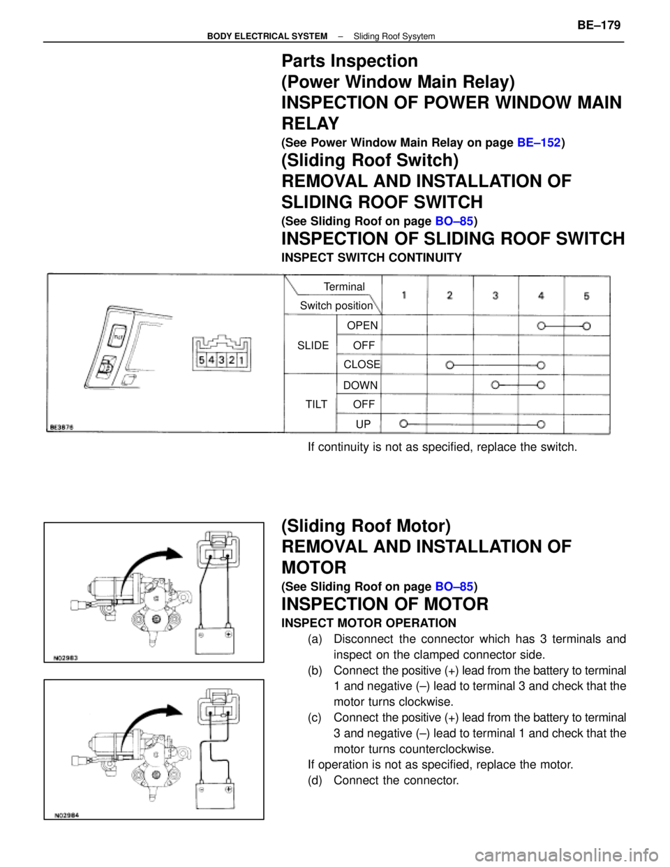
INSPECTION OF SLIDING ROOF SWITCH
INSPECT SWITCH CONTINUITY
Terminal
Switch position
SLIDE
TILT OFF
OPEN
CLOSE
OFFUP
DOWN
If continuity is not as specified, replace the switch.
(Sliding Roof Motor)
REMOVAL AND INSTALLATION OF
MOTOR
(See Sliding Roof on page
BO±85)
INSPECTION OF MOTOR
INSPECT MOTOR OPERATION
(a) Disconnect the connector which has 3 terminals andinspect on the clamped connector side.
(b) Connect the positive (+) lead from the battery to terminal
1 and negative (±) lead to terminal 3 and check that the
motor turns clockwise.
(c) Connect the positive (+) lead from the battery to terminal
3 and negative (±) lead to terminal 1 and check that the
motor turns counterclockwise.
If operation is not as specified, replace the motor.
(d) Connect the connector.
±
BODY ELECTRICAL SYSTEM Sliding Roof SysytemBE±179
WhereEverybodyKnowsYourName
Page 568 of 4087

Troubleshooting
You will find the cause of trouble more easily by properly using the tabl\
e shown below. In this table, the numbers
indicate the order of priority of the causes of trouble. Check each part in the \
order shown. If necessary, replace
the part.
See page
BE±4,21BE±4,21BE±4,20BE±4,20BE±156BE±152BE±180BE±179BE±179 ±±BE±181BE±26BE±79BE±4,20 ±±
Part
name
Trouble
AM1 FuseDOME FuseDOOR FusePOWER FuseTheft Deterrent and Door Lock Control ECUPower Window Main RelaySliding Roof Control RelaySliding Roof SwitchSliding Roof MotorSliding Rood Motor (Stones to foreign material
trapped in motor assembly)Limit SwitchIgnition SwitchDoor Courtesy SwitchECU±IG FuseWire Harness
*1 Sliding roof system does not operate.1234
*2 Sliding roof system does not operate.35467892110
Sliding roof system operates abnormally.1324
Sliding roof system stops operation half way.1342
Buzzer does not sound.123
Buzzer sounds abnormally.1
ªKey±off Sliding Roofº operation does not
operate.124536
*1: Door Lock does not operate
*2: Door Lock is normal
BE±182
±
BODY ELECTRICAL SYSTEM Sliding Roof System
WhereEverybodyKnowsYourName
Page 645 of 4087
31NoiseNOISE PRODUCED WHEN ENGINE STARTS
Whistling noise which becomes high±pitched when
accelerator strongly depressed, disappears shortly
after engine stops.Whining noise occurs when A/C is operating.
Scratching noise occurs during sudden accel-
eration, driving on rough roads or when ignition
switch is turned on.
Clicking sound heard when horn button is
pressed, then released. Whirring/grating sound
when pushed continuously.
Murmuring sound, stops when engine stops. Tick±tock noise, occurs in coordination with
blinking of flasher.
Noise occurs during window washer operation.Scratching noise occurs while engine is running,
continues a while even after engine stops.Scraping noise in time with wiper beat.
Other type of noise. Alternator noise.
A/C noise.
Fuel gauge noise.
Horn noise.
Ignition noise. Turn signal flasher noise.
Washer noise. Water temp. gauge noise.
Wiper noise.
±
BODY ELECTRICAL SYSTEM AUDIO SYSTEMBE±259
WhereEverybodyKnowsYourName
Page 763 of 4087
DESCRIPTION
The wireless door lock control system is to lock and unlock all the doors a\
t a distance, transmitting a weak radio
wave from a transmitter contained in the master ignition key.
The weak radio wave (coded differently for each key) is sent to the receiver via the rear window defo\
gger wiring.
For the function of the component parts of this system, refer to the circui\
t description in circuit inspection.
PARTS LOCATION
BE±440±
BODY ELECTRICAL SYSTEM Wireless Door Lock Control System
WhereEverybodyKnowsYourName