Page 896 of 4087

Parts NameFunction
Coolant Level
Warning SwitchThis switch is installed in the radiator reservoir tank. It lights up a \
warning light when the
coolant level becomes low.
Engine Oil Level
Warning SwitchThis switch is mounted in the engine oil pan. It lights a warning light \
when the engine oil
level is low.
Brake Fluid Level
Warning SwitchThis switch is mounted in the brake master cylinder reservoir tank. It l\
ights up a warning
light when the brake fluid level is low.
Parking Brake SwitchThis switch is on the parking brake lever bracket. Continuity in this sw\
itch is established
when the lever is released, causing a warning light to light up.
Door Courtesy SwitchContinuity is established in this switch when a door is opened, causing \
a warning light to
light up.
Warning LightsWhen an abnormality is detected in the vehicle, current is sent to these\
lights, or they are
grounded, causing them to light up.
Indicator LightsCurrent is sent to these lights, or they are grounded, causing them to l\
ight up and indicate
the vehicle's condition to the driver.
Window Washer Level
Warning SwitchThis switch is mounted in the window washer tank. It lights a warning li\
ght when the
window washer level becomes low.
±
BODY ELECTRICAL SYSTEM Cominbation MeterBE±97
WhereEverybodyKnowsYourName
Page 906 of 4087

ConnectionCheck forTester connectionConditionSpecified value
A19 A15Trip switch A/BPushContinuity
Trip switchContinuity
A19±A15Trip switch A/BFreeNo continuityTrip switchContinuity
A20 A15Trip switch RESETPushContinuityA20±A15Trip switch RESETFreeNo continuity
DOME
FuseVoltageA11±GroundConstantBattery positive voltage
Speed
SVoltageA13 A15
Ignition
switch
*3 Revolve propeller shaft0V � 11 V
SensorVoltageA13±A15switch
ON*3 Stop propeller shaft0V or 11V
C1±GroundPBattery positive voltage
C2±GroundIgnitionRBattery positive voltage
Neutral start
it hVoltageC3±Ground
Ignition
switch
ON andNBattery positive voltageswitchVoltageC4±GroundON and
shift leverDBattery positive voltage
C5±Ground
shift lever
position2Battery positive voltage
C16±Ground
osition
LBattery positive voltage
O/D OFFContinuityC18 GroundO/D OFF switchONContinuity
SwitchContinuityC18±GroundO/D OFF switchOFFNo continuity
AlternatorContinuityC15±GroundEngine stopContinuity
ºLº terminalVoltageC14±GroundEngine runningBattery positive voltage
FuelContinuityA7 GroundFuel remainderFullNo continuity
SenderContinuityA7±GroundFuel remainderEmptyContinuity
GaugeFull, Approx. 79.3 mm
(3.12 in.)Approx. 6 �
ResistanceA8±C8Float
position1/2, Approx. 193.1 mm
(76.0 in.)Approx. 32.5 �
Empty, Approx. 308.1 mm
(12.13 in.)Approx. 97 �
*Window
washer level
ContinuityB9±GroundON (float down)Continuitywasher level
warning
switchContinuityB9 Ground
(Canada)OFF (float up)No continuity
Brake fluidBrake fluid levelON (float down)Continuity
Level warning
Brake fluid level
warning SWOFF (float up)No continuity
SW and
Parking brake
SW
ContinuityC13±GroundParking brake
ON (Depress the Ped-
al))Continuity
SWParking brake
SWOFF (Release the Ped-
al)No continuity
Low oil
PressureContinuityC19 GroundEngine condition
RunningNo continuity
Pressure
Warning SWContinuityC19±GroundEngine conditionStopContinuity
Door courtesyContinuityC12 GroundDriver's andOpen (ON)Continuityy
SwitchContinuityC12±GroundDriver s and
passenger's doorClosed (OFF)No continuity
IGN fuseVoltageC14 GroundIgnition switchONBattery positive voltageVoltageC14±GroundIgnition switchLOCK or ACCNo voltage
CIG fuseVoltageA6 GroundIgnition switchACC or ONBattery positive voltageVoltageA6±GroundIgnition switchLOCK or STARTNo voltage
BE±107±
BODY ELECTRICAL SYSTEM Combination Meter
WhereEverybodyKnowsYourName
Page 1192 of 4087
INSTALLATION
Body Sealer
Body Sealer Braze
(both sides)
2. Braze the quarter panel connection.
NOTICE: Before performing these operations,place a wet rag on the roof panel to protect it fromdamage.
1. Before temporarily installing the new parts, apply body sealer to the windshield header
panel and the back window upper frame.
HINT: Apply just enough sealer for the new parts
to make contact.
BODY PANEL REPLACEMENTRE-35
WhereEverybodyKnowsYourName
Page 1194 of 4087
INSTALLATION
Body Sealer
Body Sealer Braze (both sides)
2. Braze the quarter panel connection.
NOTICE: Before performing these operations,place a wet rag on the roof panel to protect it fromdamage.
1. Before temporarily installing the new parts, apply body sealer to the windshield header
panel and back window upper frame.
HINT: Apply just enough sealer for the new parts
to make contact.
BODY PANEL REPLACEMENTRE-37
WhereEverybodyKnowsYourName
Page 1250 of 4087

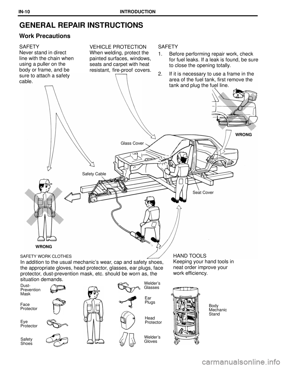
GENERAL REPAIR INSTRUCTIONS
Work Precautions
SAFETY
1. Before performing repair work, checkfor fuel leaks. If a leak is found, be sure
to close the opening totally.
2. If it is necessary to use a frame in the area of the fuel tank, first remove the
tank and plug the fuel line.
VEHICLE PROTECTION
When welding, protect the
painted surfaces, windows,
seats and carpet with heat
resistant, fire-proof covers.
SAFETY
Never stand in direct
line with the chain when
using a puller on the
body or frame, and be
sure to attach a safety
cable.
WRONG
Glass Cover
Safety Cable Seat Cover
WRONG
SAFETY WORK CLOTHES
HAND TOOLS
Keeping your hand tools in
neat order improve your
work efficiency.
In addition to the usual mechanic's wear, cap and safety shoes,
the appropriate gloves, head protector, glasses, ear plugs, face
protector, dust-prevention mask, etc. should be worn as, the
situation demands.
Dust-
Prevention
Mask Welder's
Glasses
Ear
Plugs Body
Mechanic
Stand
Face
Protector
Head
Protector
Eye
Protector
Welder's
Gloves
Safety
Shoes
INTRODUCTIONIN-10
WhereEverybodyKnowsYourName
Page 2759 of 4087

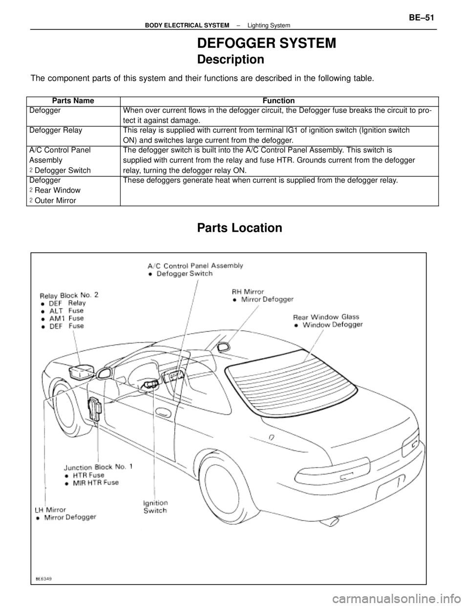
DEFOGGER SYSTEM
Description
The component parts of this system and their functions are described in the\
following table.
��������� ���������Parts Name������������������\
���������� ������������������\
����������Function
��������� ���������Defogger������������������\
���������� ������������������\
����������When over current flows in the defogger circuit, the Defogger fuse break\
s the circuit to pro-
tect it against damage.
��������� �
��������
���������
Defogger Relay������������������\
���������� �
������������������\
���������
������������������\
����������
This relay is supplied with current from terminal IG1 of ignition switch\
(Ignition switch
ON) and switches large current from the defogger.
��������� �
��������
���������
A/C Control Panel
Assembly
�
Defogger Switch������������������\
���������� �
������������������\
���������
������������������\
����������
The defogger switch is built into the A/C Control Panel Assembly. This switch is
supplied with current from the relay and fuse HTR. Grounds current from \
the defogger
relay, turning the defogger relay ON.
��������� �
��������
�
��������
���������
Defogger
�
Rear Window
� Outer Mirror������������������\
���������� �
������������������\
���������
�
������������������\
���������
������������������\
����������
These defoggers generate heat when current is supplied from the defogger\
relay.
Parts Location
±
BODY ELECTRICAL SYSTEM Lighting SystemBE±51
WhereEverybodyKnowsYourName
Page 3126 of 4087

When scrapping vehicle
HINT: Have a battery ready as the power source to deploy the
airbag.
1. DISCONNECT NEGATIVE (±) TERMINAL CABLE FROM BATTERY
CAUTION: Work must be started after 90 seconds from
the time the ignition switch is turned to the LOCK posi-
tion and the negative (±) terminal cable is disconnected
from the battery (See page RS±2).
2. CONFIRM FUNCTIONING OF SST (See page RS±27)
SST 09082±00700
3. INSTALL SST CAUTION: Check that there is no looseness in the steer-
ing wheel and steering wheel pad.
(a) Remove the No.1 under cover.
(b) Disconnect the airbag connector of the spiral cable.
(c) Connect the SST connector to the airbag connector of the spiral cable.
SST 09082±00700
(d) Move the SST to at least 10 m (33 ft) from the front of the vehicle.
(e) Close all the doors and windows of the vehicle. NOTICE: Take care not to damage the SST wire harness.
(f) Connect the SST red clip to the battery positive (+) terminal and the black clip to the battery negative (±) terminal.
RS±22±
SUPPLEMENTAL RESTRAINT SYSTEM STEERING WHEEL PAD AND SPIRAL CABLE
WhereEverybodyKnowsYourName
Page 3140 of 4087

(b) Move the SST to at least 10 m (33 ft) from the front of thevehicle.
(c) Close all the doors and windows of the vehicle. NOTICE: Take care not change the SST wire harness.
(d) Connect the SST red clip to the battery positive (+) terminal and the black clip to the battery negative (±) terminal.
5. DEPLOY AIRBAG
(a) Confirm that no±one is inside the vehicle or within 10 m (33ft) of the vehicle.
(b) Press the SST activation switch and deploy the airbag. HINT: The airbag deploys simultaneously as the LED of the
SST activation switch lights up.
6. DISPOSAL OF FRONT PASSENGER AIRBAG ASSEMBLY
NOTICE:
w The front passenger airbag assembly is very out not
when the airbag is deployed, so leave it alone for at least
30 minutes after deployment.
w Use gloves and safety glasses when handling a front
passenger airbag assembly with deployed airbag.
w Do not apply water, etc., to a front passenger airbag
assembly with deployed airbag.
w Always wash your hands with water after completing the
operation.
When scrapping a vehicle, deploy the airbag and scrap the
vehicle with the front passenger airbag assembly still
installed.
RS±36
±
SUPPLEMENTAL RESTRAINT SYSTEM FRONT PASSENGER AIRBAG ASSEMBLY
WhereEverybodyKnowsYourName