Page 2093 of 4087
ON±VEHICLE INSPECTION
SPARK TEST
CHECK THAT SPARK OCCURS(a) Remove the No.3 timing belt covers.(See steps 2 to 8 on pages IG±11 to 13)
(b) Disconnect the high±tension cords (from the ignition
coils) from the distributor caps.
(c) Hold the end about 12.5 mm (0.50 in.) from the body ground.
(d) Check if spark occurs while engine is being cranked.
HINT: To prevent gasoline from being injected from injectors
during this test, crank the engine for no more than 1±2 se-
conds at a time.
If the spark does not occur, perform the test as follows:
(e) Reconnect the high±tension cords to the distributor caps.
(f) Reinstall the No.3 timing belt covers. (See steps 5 to 11 on pages IG±17 to 19)
IG±6
±
IGNITION SYSTEM On±Vehicle Inspection
WhereEverybodyKnowsYourName
Page 2100 of 4087
6. REMOVE VSV FOR EVAP SYSTEMRemove the two bolts, and disconnect the VSV from cylinder
head and timing belt cover.
7. REMOVE RH NO.3 TIMING BELT COVER Remove the three bolts and timing belt cover.
8. REMOVE LH NO.3 TIMING BELT COVER (a) Remove the four mounting bolts.
(b) Disconnect the cord grommet from the timing belt cover,
and remove the timing belt cover.
(c) Remove the cord grommet from the high±tension cord.
9. REMOVE HIGH±TENSION CORDS (a) Disconnect the high±tension cords from the spark plugs
and distributor caps. Disconnect the high±tension cords
at the rubber boot. Do not pull on the cords.
NOTICE: Pulling on or bending the cords may damage
the conductor inside.
±
IGNITION SYSTEM High±Tension Cords and Cord ClampsIG±13
WhereEverybodyKnowsYourName
Page 2104 of 4087
wAlign the spline of the ignition coil with the spline of
the holder, and slide on the holder.
NOTICE: Check that holder is correctly installed to the
grommet and ignition coil as shown in the illustration. w Check that the lock claw of the holder is engaged
by lightly pulling the holder.
5. INSTALL RH NO.3 TIMING BELT COVER (a) Install the three gaskets to the timing belt cover.
(b) Fit portion A of the timing belt cover, matching it with the
lower high±tension cord cover.
(c) Install the timing belt cover with the three bolts.
±
IGNITION SYSTEM High±Tension Cords and Cord ClampsIG±17
WhereEverybodyKnowsYourName
Page 2105 of 4087
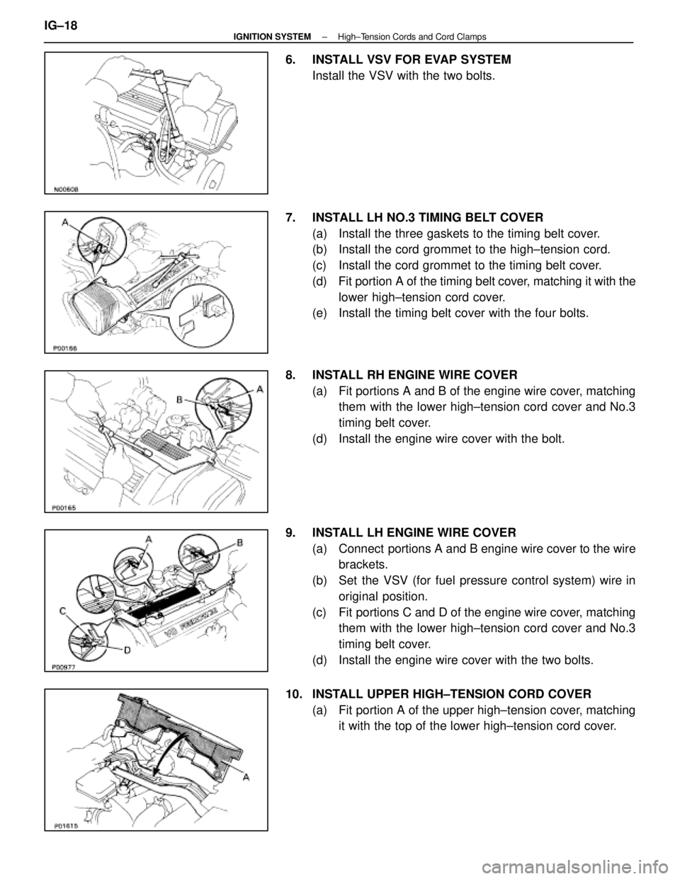
6. INSTALL VSV FOR EVAP SYSTEMInstall the VSV with the two bolts.
7. INSTALL LH NO.3 TIMING BELT COVER (a) Install the three gaskets to the timing belt cover.
(b) Install the cord grommet to the high±tension cord.
(c) Install the cord grommet to the timing belt cover.
(d) Fit portion A of the timing belt cover, matching it with the
lower high±tension cord cover.
(e) Install the timing belt cover with the four bolts.
8. INSTALL RH ENGINE WIRE COVER (a) Fit portions A and B of the engine wire cover, matchingthem with the lower high±tension cord cover and No.3
timing belt cover.
(d) Install the engine wire cover with the bolt.
9. INSTALL LH ENGINE WIRE COVER (a) Connect portions A and B engine wire cover to the wirebrackets.
(b) Set the VSV (for fuel pressure control system) wire in original position.
(c) Fit portions C and D of the engine wire cover, matching them with the lower high±tension cord cover and No.3
timing belt cover.
(d) Install the engine wire cover with the two bolts.
10. INSTALL UPPER HIGH±TENSION CORD COVER (a) Fit portion A of the upper high±tension cover, matchingit with the top of the lower high±tension cord cover.
IG±18
±
IGNITION SYSTEM High±Tension Cords and Cord Clamps
WhereEverybodyKnowsYourName
Page 2112 of 4087
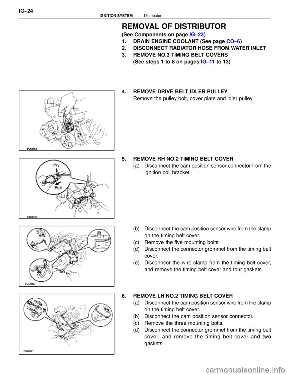
REMOVAL OF DISTRIBUTOR
(See Components on page IG±23)
1. DRAIN ENGINE COOLANT (See page CO±6)
2. DISCONNECT RADIATOR HOSE FROM WATER INLET
3. REMOVE NO.3 TIMING BELT COVERS
(See steps 1 to 8 on pages IG±11 to 13)
4. REMOVE DRIVE BELT IDLER PULLEY Remove the pulley bolt, cover plate and idler pulley.
5. REMOVE RH NO.2 TIMING BELT COVER (a) Disconnect the cam position sensor connector from theignition coil bracket.
(b) Disconnect the cam position sensor wire from the clamp
on the timing belt cover.
(c) Remove the five mounting bolts.
(d) Disconnect the connector grommet from the timing belt cover.
(e) Disconnect the wire clamp from the timing belt cover, and remove the timing belt cover and four gaskets.
6. REMOVE LH NO.2 TIMING BELT COVER (a) Disconnect the cam position sensor wire from the clamp
on the timing belt cover.
(b) Disconnect the cam position sensor connector.
(c) Remove the three mounting bolts.
(d) Disconnect the connector grommet from the timing belt cover, and remove the timing belt cover and two
gaskets.
IG±24
±
IGNITION SYSTEM Distributor
WhereEverybodyKnowsYourName
Page 2115 of 4087
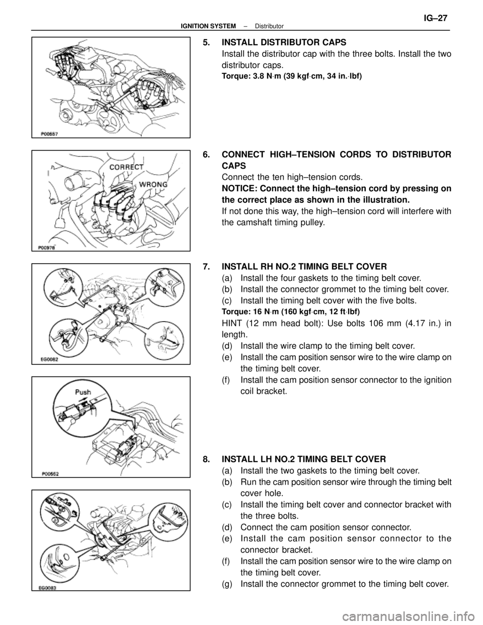
5. INSTALL DISTRIBUTOR CAPSInstall the distributor cap with the three bolts. Install the two
distributor caps.
Torque: 3.8 N Vm (39 kgf Vcm, 34 in. Vlbf)
6. CONNECT HIGH±TENSION CORDS TO DISTRIBUTOR
CAPS
Connect the ten high±tension cords.
NOTICE: Connect the high±tension cord by pressing on
the correct place as shown in the illustration.
If not done this way, the high±tension cord will interfere with
the camshaft timing pulley.
7. INSTALL RH NO.2 TIMING BELT COVER (a) Install the four gaskets to the timing belt cover.
(b) Install the connector grommet to the timing belt cover.
(c) Install the timing belt cover with the five bolts.
Torque: 16 N Vm (160 kgf Vcm, 12 ft Vlbf)
HINT (12 mm head bolt): Use bolts 106 mm (4.17 in.) in
length.
(d) Install the wire clamp to the timing belt cover.
(e) Install the cam position sensor wire to the wire clamp on
the timing belt cover.
(f) Install the cam position sensor connector to the ignition coil bracket.
8. INSTALL LH NO.2 TIMING BELT COVER (a) Install the two gaskets to the timing belt cover.
(b) Run the cam po sition sensor wire through the timing belt
cover hole.
(c) Install the timing belt cover and connector bracket with the three bolts.
(d) Connect the cam position sensor connector.
(e) In sta ll th e ca m po sitio n se n so r c onnector to the
connector bracket.
(f) Install the cam position sensor wire to the wire clamp on
the timing belt cover.
(g) Install the connector grommet to the timing belt cover.
±
IGNITION SYSTEM DistributorIG±27
WhereEverybodyKnowsYourName
Page 2116 of 4087
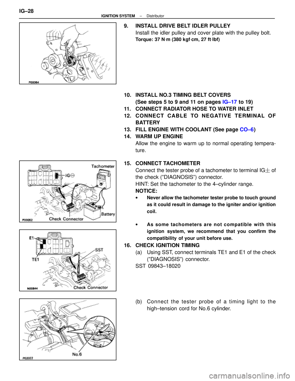
9. INSTALL DRIVE BELT IDLER PULLEYInstall the idler pulley and cover plate with the pulley bolt.
Torque: 37 N Vm (380 kgf Vcm, 27 ft Vlbf)
10. INSTALL NO.3 TIMING BELT COVERS
(See steps 5 to 9 and 11 on pages IG±17 to 19)
11. CONNECT RADIATOR HOSE TO WATER INLET
12. C O N N E C T C A B L E TO N E G AT I V E T E R M I N A L O F BATTERY
13. FILL ENGINE WITH COOLANT (See page CO±6)
14. WARM UP ENGINE Allow the engine to warm up to normal operating tempera-
ture.
15. CONNECT TACHOMETER Connect the tester probe of a tachometer to terminal IG � of
the check (ºDIAGNOSISº) connector.
HINT: Set the tachometer to the 4±cylinder range.
NOTICE:
w Never allow the tachometer tester probe to touch ground
as it could result in damage to the igniter and/or ignition
coil.
w As some tachometers are not compatible with this
ignition system, we recommend that you confirm the
compatibility of your unit before use.
16. CHECK IGNITION TIMING
(a) Using SST, connect terminals TE1 and E1 of the check(ºDIAGNOSISº) connector.
SST 09843±18020
(b) C onnect the tester probe of a timing light to the
high±tension cord for No.6 cylinder.
IG±28
±
IGNITION SYSTEM Distributor
WhereEverybodyKnowsYourName
Page 2130 of 4087
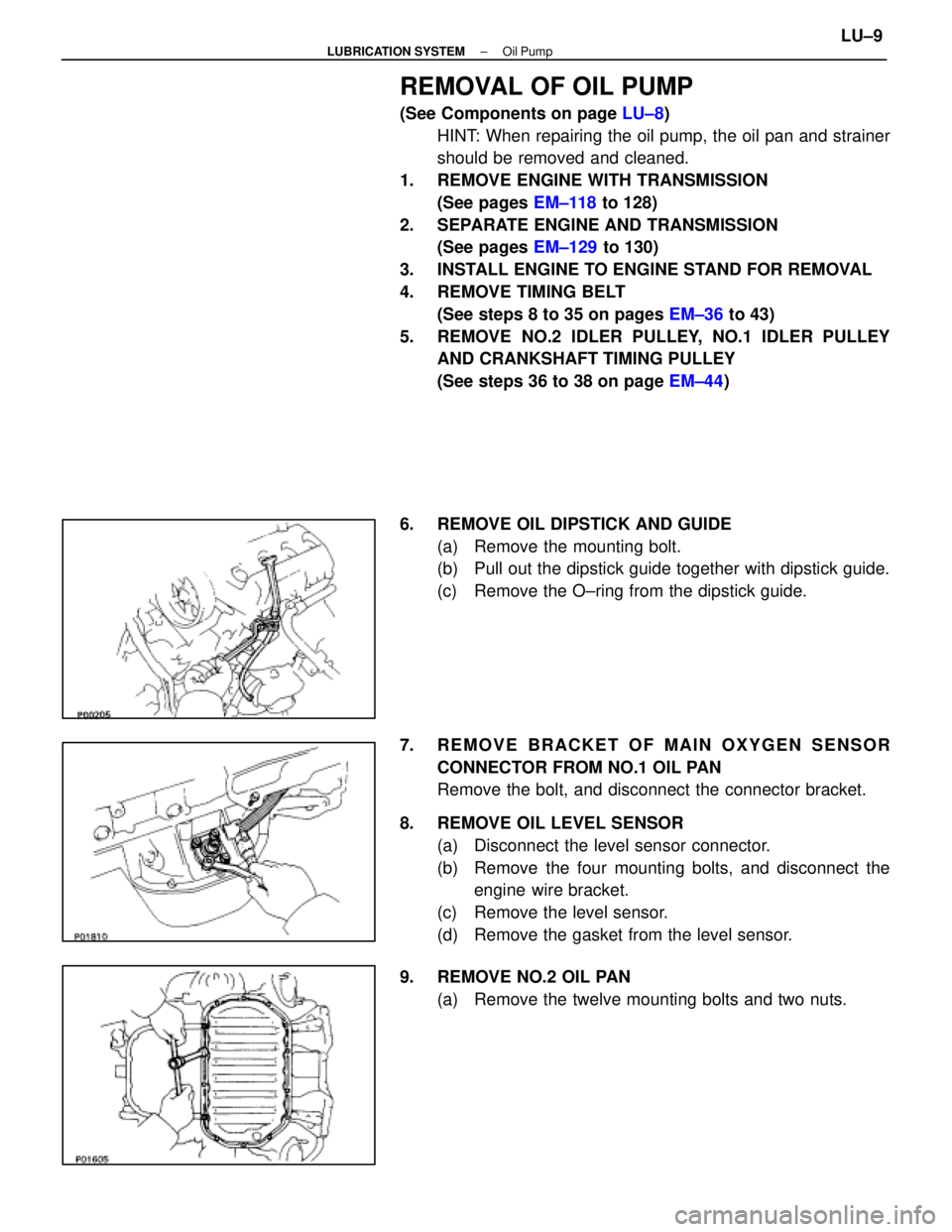
REMOVAL OF OIL PUMP
(See Components on page LU±8)
HINT: When repairing the oil pump, the oil pan and strainer
should be removed and cleaned.
1. REMOVE ENGINE WITH TRANSMISSION (See pages EM±118 to 128)
2. SEPARATE ENGINE AND TRANSMISSION (See pages EM±129 to 130)
3. INSTALL ENGINE TO ENGINE STAND FOR REMOVAL
4. REMOVE TIMING BELT (See steps 8 to 35 on pages EM±36 to 43)
5. REMOVE NO.2 IDLER PULLEY, NO.1 IDLER PULLEY AND CRANKSHAFT TIMING PULLEY
(See steps 36 to 38 on page EM±44)
6. REMOVE OIL DIPSTICK AND GUIDE (a) Remove the mounting bolt.
(b) Pull out the dipstick guide together with dipstick guide.
(c) Remove the O±ring from the dipstick guide.
7. REMOVE BRACKET OF MAIN OXYGEN SENSOR CONNECTOR FROM NO.1 OIL PAN
Remove the bolt, and disconnect the connector bracket.
8. REMOVE OIL LEVEL SENSOR (a) Disconnect the level sensor connector.
(b) Remove the four mounting bolts, and disconnect theengine wire bracket.
(c) Remove the level sensor.
(d) Remove the gasket from the level sensor.
9. REMOVE NO.2 OIL PAN (a) Remove the twelve mounting bolts and two nuts.
±
LUBRICATION SYSTEM Oil PumpLU±9
WhereEverybodyKnowsYourName