Page 2216 of 4087
(b) Check that the timing marks of the camshaft timingpulleys and timing belt rear plates aligned.
If not, turn the crankshaft one revolution (360 5) and align the
mark as above.
20. INSPECT VALVE CLEARANCE (a) Check only those valves indicated.w Using a feeler gauge, measure the clearance
between the valve lifter and camshaft.
w Record the out±of±specification valve clearance
measurements. They will be used later to
determine the required replacement adjusting
shim.
Valve clearance (Cold):
Intake 0.15±0.25 mm (0.006±0.010 in.)
Exhaust 0.25±0.35 mm (0.010±0.014 in.)
(b) Turn the crankshaft one revolution (360 °), and align the
mark as above. (See procedure step in 19 (a))
(c) Check only the valves indicated as shown. Measure the
valve clearance.
(See procedure in step (a))
EM±16
±
ENGINE MECHANICAL Engine Tune±Up
WhereEverybodyKnowsYourName
Page 2225 of 4087

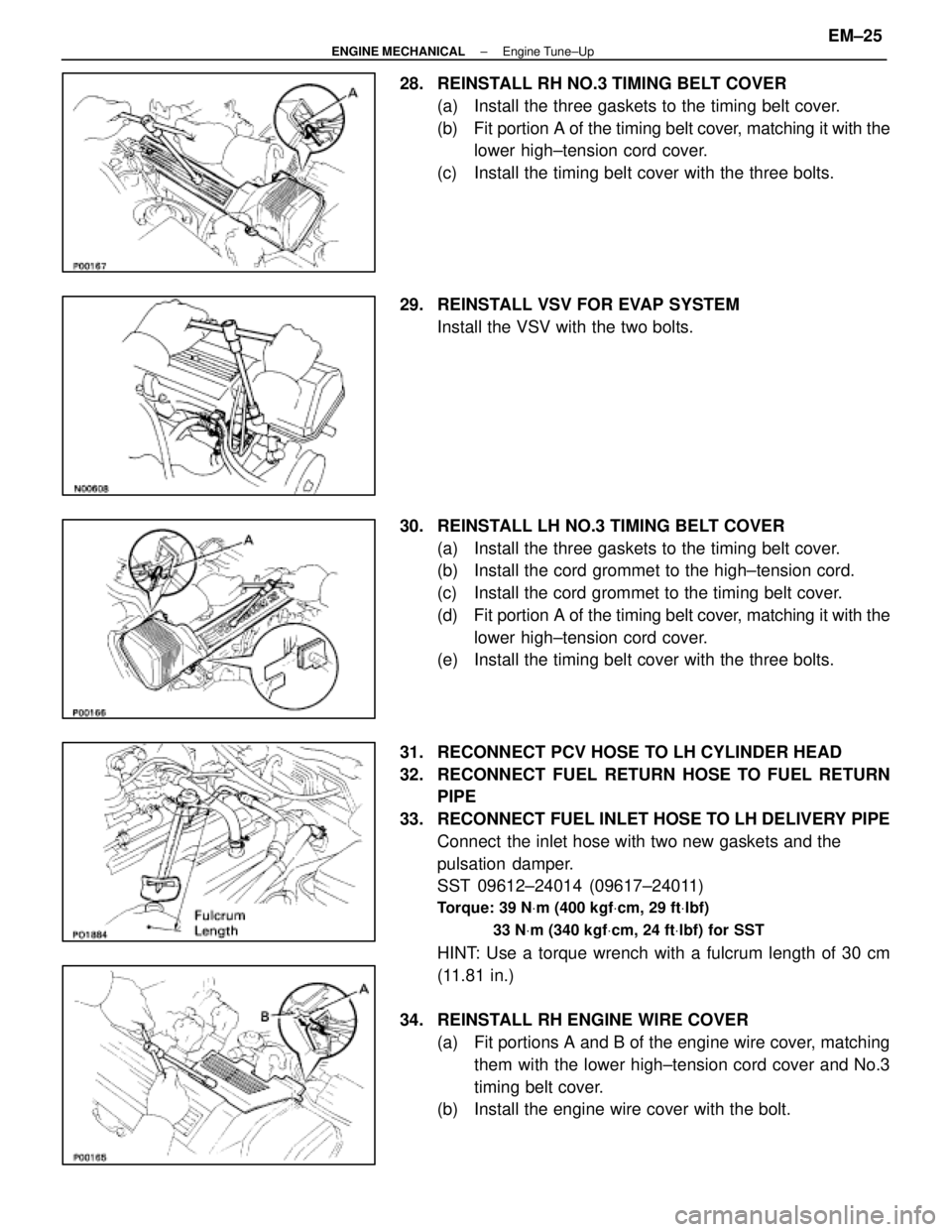
28. REINSTALL RH NO.3 TIMING BELT COVER(a) Install the three gaskets to the timing belt cover.
(b) Fit portion A of the timing belt cover, matching it with the
lower high±tension cord cover.
(c) Install the timing belt cover with the three bolts.
29. REINSTALL VSV FOR EVAP SYSTEM Install the VSV with the two bolts.
30. REINSTALL LH NO.3 TIMING BELT COVER (a) Install the three gaskets to the timing belt cover.
(b) Install the cord grommet to the high±tension cord.
(c) Install the cord grommet to the timing belt cover.
(d) Fit portion A of the timing belt cover, matching it with the
lower high±tension cord cover.
(e) Install the timing belt cover with the three bolts.
31. RECONNECT PCV HOSE TO LH CYLINDER HEAD
32. RECONNECT FUEL RETURN HOSE TO FUEL RETURN PIPE
33. RECONNECT FUEL INLET HOSE TO LH DELIVERY PIPE Connect the inlet hose with two new gaskets and the
pulsation damper.
SST 09612±24014 (09617±24011)
Torque: 39 N Vm (400 kgf Vcm, 29 ft Vlbf)
33 N Vm (340 kgf Vcm, 24 ft Vlbf) for SST
HINT: Use a torque wrench with a fulcrum length of 30 cm
(11.81 in.)
34. REINSTALL RH ENGINE WIRE COVER (a) Fit portions A and B of the engine wire cover, matchingthem with the lower high±tension cord cover and No.3
timing belt cover.
(b) Install the engine wire cover with the bolt.
±
ENGINE MECHANICAL Engine Tune±UpEM±25
WhereEverybodyKnowsYourName
Page 2226 of 4087

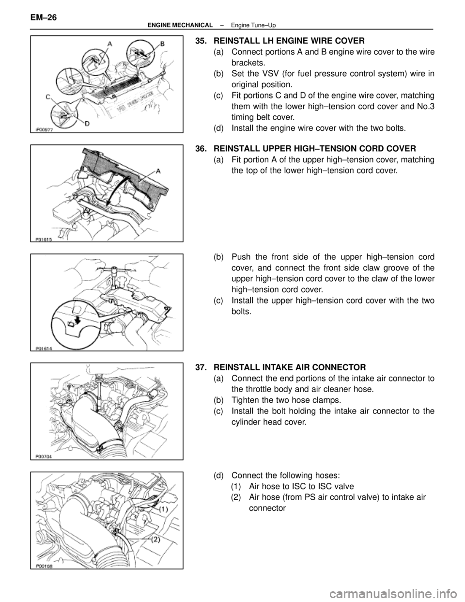
35. REINSTALL LH ENGINE WIRE COVER(a) Connect portions A and B engine wire cover to the wirebrackets.
(b) Set the VSV (for fuel pressure control system) wire in
original position.
(c) Fit portions C and D of the engine wire cover, matching them with the lower high±tension cord cover and No.3
timing belt cover.
(d) Install the engine wire cover with the two bolts.
36. REINSTALL UPPER HIGH±TENSION CORD COVER (a) Fit portion A of the upper high±tension cover, matchingthe top of the lower high±tension cord cover.
(b) Push the front side of the upper high±tension cord cover, and connect the front side claw groove of the
upper high±tension cord cover to the claw of the lower
high±tension cord cover.
(c) Install the upper high±tension cord cover with the two bolts.
37. REINSTALL INTAKE AIR CONNECTOR (a) Connect the end portions of the intake air connector tothe throttle body and air cleaner hose.
(b) Tighten the two hose clamps.
(c) Install the bolt holding the intake air connector to the cylinder head cover.
(d) Connect the following hoses: (1) Air hose to ISC to ISC valve
(2) Air hose (from PS air control valve) to intake air connector
EM±26
±
ENGINE MECHANICAL Engine Tune±Up
WhereEverybodyKnowsYourName
Page 2230 of 4087
COMPRESSION CHECK
HINT: If there is lack of power, excessive oil consumption or
poor fuel economy, measure the compression pressure.
1. WARM UP AND STOP ENGINE Allow the engine to warm up to normal operating tempera-
ture.
2. REMOVE NO.3 TIMING BELT COVERS (See steps 1, 5 to 10 and 14 on pages EM±11 to 13)
3. DISCONNECT COLD START INJECTOR CONNECTOR
4. DISCONNECT RH CAM POSITION SENSOR CONNECTOR
(a) Disconnect the connector from the ignition coil bracket.
(b) Disconnect the sensor connector.
5. DISCONNECT LH CAM POSITION SENSOR CONNECTOR
6. REMOVE SPARK PLUGS (a) Disconnect the eight high±tension cords from the sparkplugs.
Disconnect the high±tension cords at rubber boot. Do
not pull on the cords.
NOTICE: Pulling on or bending the cords may damage
the conductor inside.
EM±30
±
ENGINE MECHANICAL Compression Check
WhereEverybodyKnowsYourName
Page 2232 of 4087
9. RECONNECT RH CAM POSITION SENSOR CONNECTOR
(a) Connect the sensor connector.
(b) Connect the connector to the ignition coil bracket.
10. RECONNECT LH CAM POSITION SENSOR CONNECTOR
11. RECONNECT COLD START INJECTOR CONNECTOR
12. REINSTALL NO.3 TIMING BELT COVERS (See steps 28 to 30, 34 to 37, 40 and 41 on pages EM±25
to 27)
EM±32
±
ENGINE MECHANICAL Compression Check
WhereEverybodyKnowsYourName
Page 2233 of 4087
TIMING BELT
COMPONENTS FOR REMOVAL AND
INSTALLATION
±
ENGINE MECHANICAL Timing BeltEM±33
WhereEverybodyKnowsYourName
Page 2234 of 4087
COMPONENTS FOR REMOVAL AND
INSTALLATION (Cont'd)
EM±34±
ENGINE MECHANICAL Timing Belt
WhereEverybodyKnowsYourName
Page 2235 of 4087

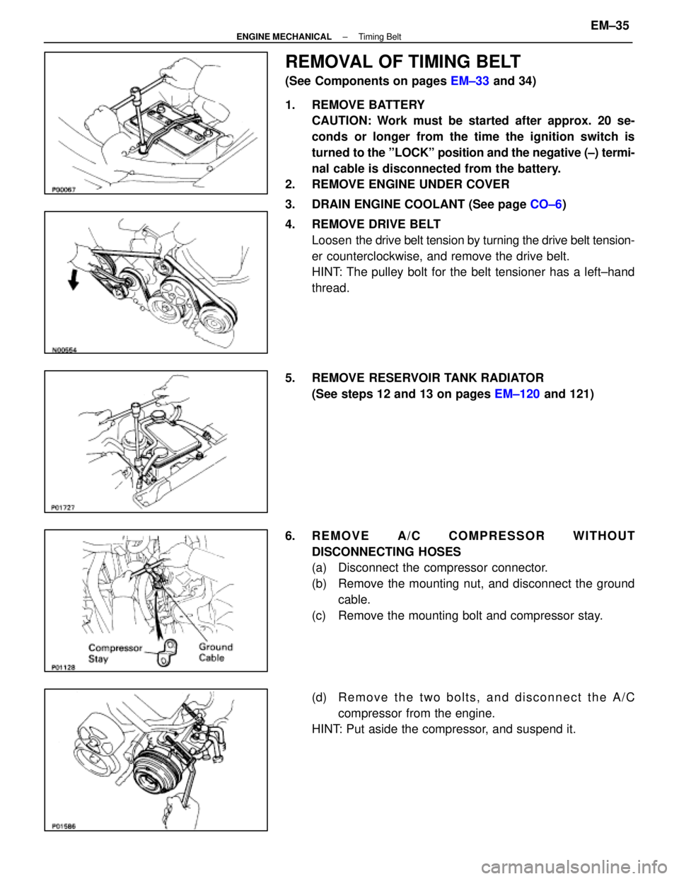
REMOVAL OF TIMING BELT
(See Components on pages EM±33 and 34)
1. REMOVE BATTERY CAUTION: Work must be started after approx. 20 se-
conds or longer from the time the ignition switch is
turned to the ºLOCKº position and the negative (±) termi-
nal cable is disconnected from the battery.
2. REMOVE ENGINE UNDER COVER
3. DRAIN ENGINE COOLANT (See page CO±6)
4. REMOVE DRIVE BELT Loosen the drive belt tension by turning the drive belt tension-
er counterclockwise, and remove the drive belt.
HINT: The pulley bolt for the belt tensioner has a left±hand
thread.
5. REMOVE RESERVOIR TANK RADIATOR (See steps 12 and 13 on pages EM±120 and 121)
6. REMOVE A/C COMPRESSOR WITHOUT DISCONNECTING HOSES
(a) Disconnect the compressor connector.
(b) Remove the mounting nut, and disconnect the groundcable.
(c) Remove the mounting bolt and compressor stay.
(d) R e m o v e t h e t w o b o l t s , a n d d i s c onnect the A/C
compressor from the engine.
HINT: Put aside the compressor, and suspend it.
±
ENGINE MECHANICAL Timing BeltEM±35
WhereEverybodyKnowsYourName