Page 2140 of 4087

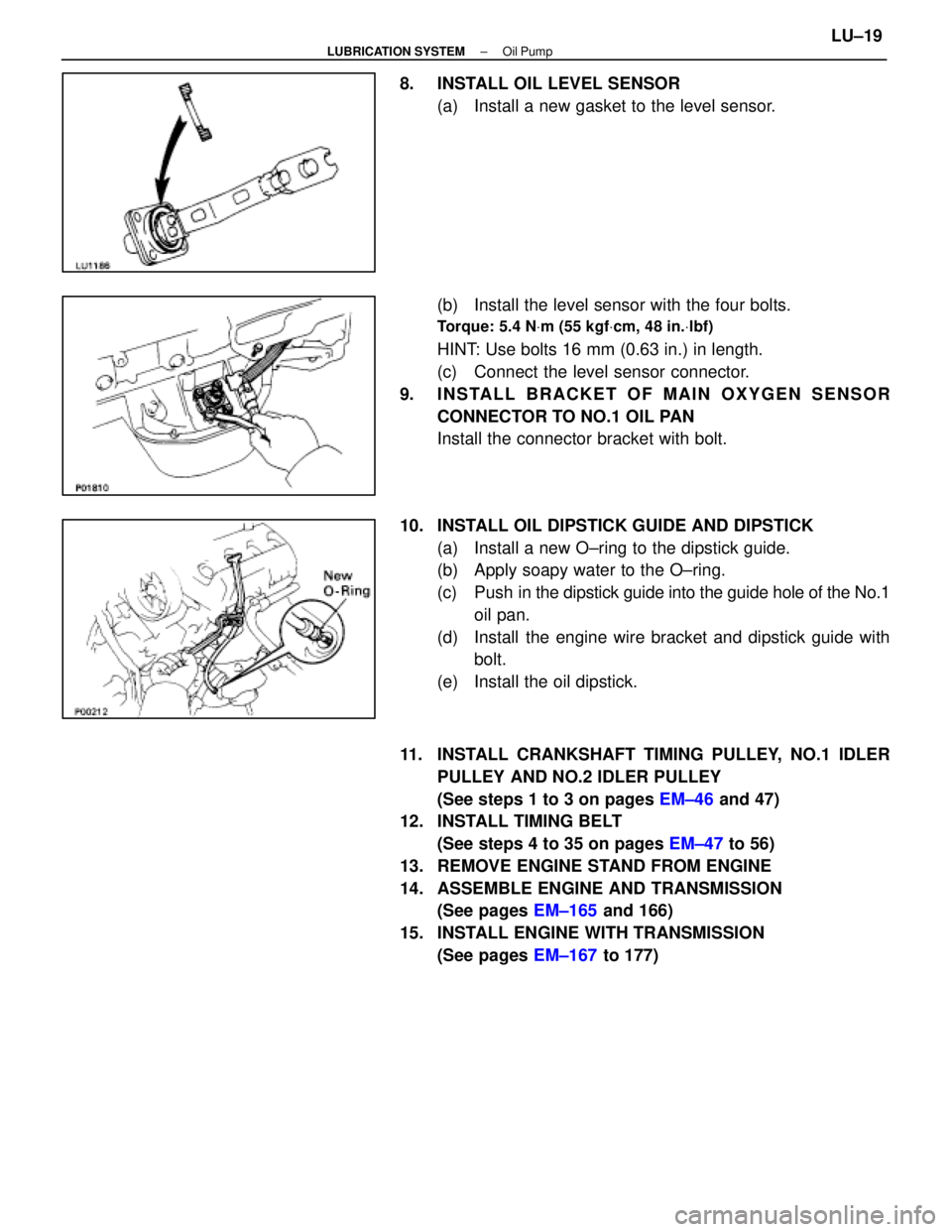
8. INSTALL OIL LEVEL SENSOR(a) Install a new gasket to the level sensor.
(b) Install the level sensor with the four bolts.
Torque: 5.4 N Vm (55 kgf Vcm, 48 in. Vlbf)
HINT: Use bolts 16 mm (0.63 in.) in length.
(c) Connect the level sensor connector.
9. INSTALL BRACKET OF MAIN OXYGEN SENSOR CONNECTOR TO NO.1 OIL PAN
Install the connector bracket with bolt.
10. INSTALL OIL DIPSTICK GUIDE AND DIPSTICK (a) Install a new O±ring to the dipstick guide.
(b) Apply soapy water to the O±ring.
(c) Push in the dipstick guide into the guide hole of the No.1
oil pan.
(d) Install the engine wire bracket and dipstick guide with bolt.
(e) Install the oil dipstick.
11. INSTALL CRANKSHAFT TIMING PULLEY, NO.1 IDLER PULLEY AND NO.2 IDLER PULLEY
(See steps 1 to 3 on pages EM±46 and 47)
12. INSTALL TIMING BELT
(See steps 4 to 35 on pages EM±47 to 56)
13. REMOVE ENGINE STAND FROM ENGINE
14. ASSEMBLE ENGINE AND TRANSMISSION (See pages EM±165 and 166)
15. INSTALL ENGINE WITH TRANSMISSION (See pages EM±167 to 177)
±
LUBRICATION SYSTEM Oil PumpLU±19
WhereEverybodyKnowsYourName
Page 2142 of 4087

REMOVAL OF OIL PUMP
(See Components on page LU±9)
HINT: When repairing the oil pump, the oil pan and strainer
should be removed and cleaned.
1. REMOVE ENGINE WITH TRANSMISSION (See pages EM±62 to 72)
2. SEPARATE ENGINE AND TRANSMISSION (See page EM±73)
3. INSTALL ENGINE TO ENGINE STAND FOR REMOVAL
4. REMOVE TIMING BELT (See steps 2 to 10 on pages EM±24 to 26)
5. REMOVE IDLER PULLEY AND CRANKSHAFT TIMING PULLEY
(See steps 11 and 12 on page EM±26)
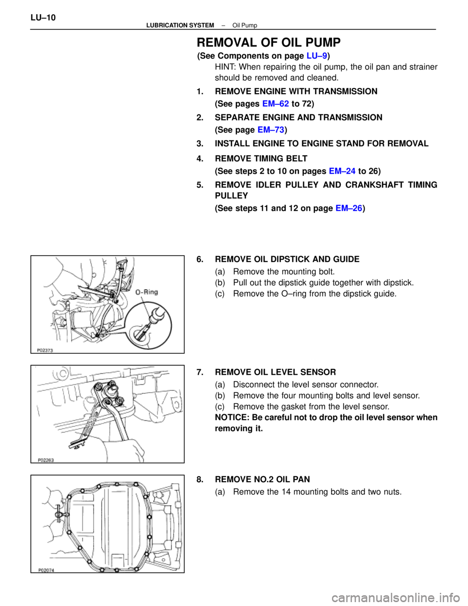
6. REMOVE OIL DIPSTICK AND GUIDE (a) Remove the mounting bolt.
(b) Pull out the dipstick guide together with dipstick.
(c) Remove the O±ring from the dipstick guide.
7. REMOVE OIL LEVEL SENSOR (a) Disconnect the level sensor connector.
(b) Remove the four mounting bolts and level sensor.
(c) Remove the gasket from the level sensor.
NOTICE: Be careful not to drop the oil level sensor when
removing it.
8. REMOVE NO.2 OIL PAN (a) Remove the 14 mounting bolts and two nuts.
LU±10
±
LUBRICATION SYSTEM Oil Pump
WhereEverybodyKnowsYourName
Page 2150 of 4087
6. INSTALL OIL LEVEL SENSOR(a) Install a new gasket to the level sensor.
(b) Install the level sensor with the four bolts.
Torque: 5.4 N Vm (55 kgf Vcm, 48 in. Vlbf)
(c) Connect the level sensor connector.
7. INSTALL OIL DIPSTICK GUIDE AND DIPSTICK (a) Install a new O±ring on the dipstick guide.
(b) Apply soapy water on the O±ring.
(c) Push in the dipstick guide into the guide hole of the No.1
oil pan.
(d) Install the guide with the mounting bolt.
8. INSTALL CRANKSHAFT TIMING PULLEY AND IDLER PULLEY
(See steps 1 and 2 on page EM±29)
9. INSTALL TIMING BELT (See steps 3 to 14 on pages EM±29 to 33)
10. REMOVE ENGINE STAND FROM ENGINE
11. ASSEMBLE ENGINE AND TRANSMISSION (See page EM±103)
12. INSTALL ENGINE WITH TRANSMISSION (See pages EM±104 to 112)
LU±18
±
LUBRICATION SYSTEM Oil Pump
WhereEverybodyKnowsYourName
Page 2157 of 4087

MAINTENANCE OPERATIONS
MA035±04
ENGINE
Cold Engine Operations
1. REPLACE TIMING BELT
(a) Remove the timing belt.(See page EG±46)
(b) Install the timing belt. (See page EG±59)
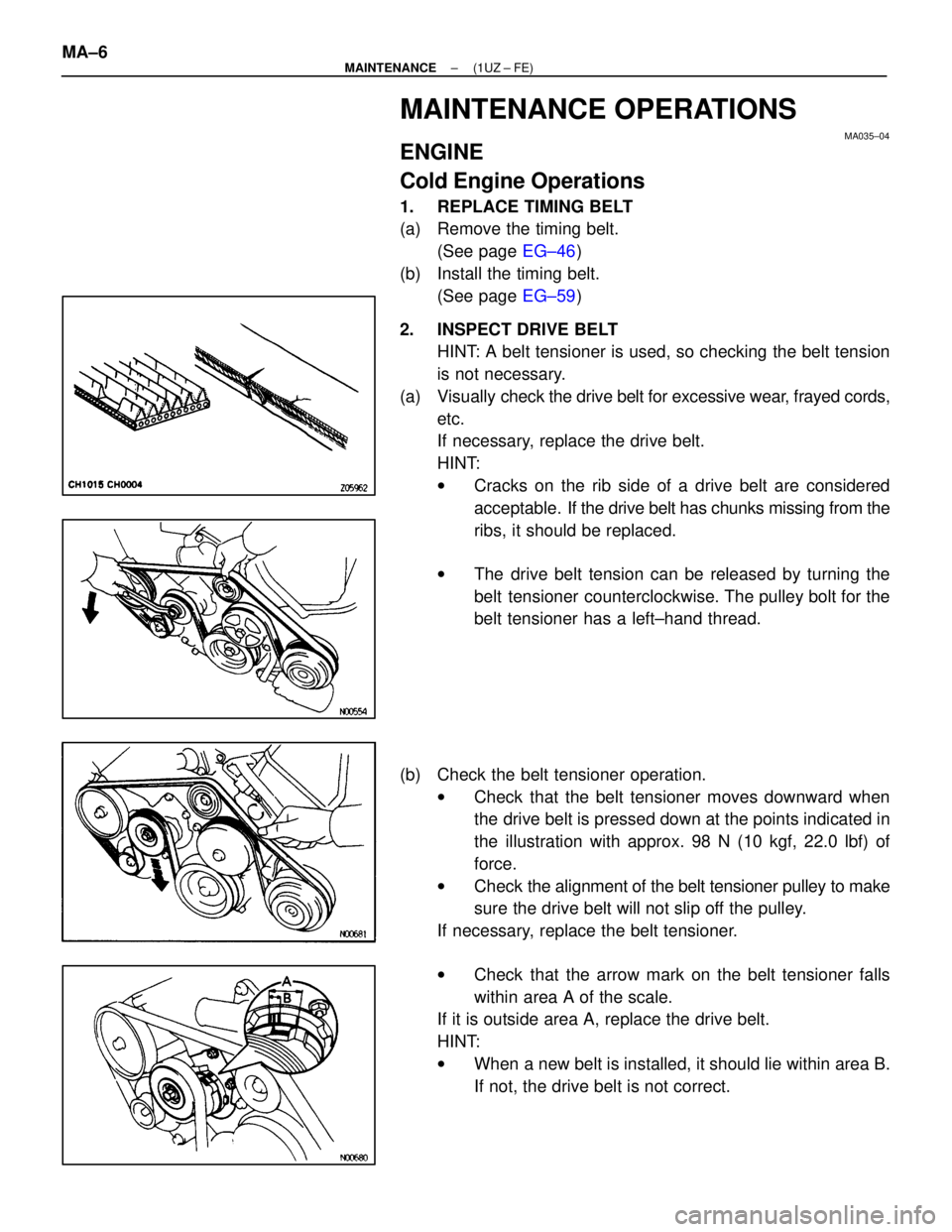
2. INSPECT DRIVE BELT HINT: A belt tensioner is used, so checking the belt tension
is not necessary.
(a) Visually check the drive belt for excessive wear, frayed cords,
etc.
If necessary, replace the drive belt.
HINT:
w Cracks on the rib side of a drive belt are considered
acceptable. If the drive belt has chunks missing from the
ribs, it should be replaced.
w The drive belt tension can be released by turning the
belt tensioner counterclockwise. The pulley bolt for the
belt tensioner has a left±hand thread.
(b) Check the belt tensioner operation. wCheck that the belt tensioner moves downward when
the drive belt is pressed down at the points indicated in
the illustration with approx. 98 N (10 kgf, 22.0 lbf) of
force.
w Check the ali gnment of the belt tensioner pulley to make
sure the drive belt will not slip off the pulley.
If necessary, replace the belt tensioner.
w Check that the arrow mark on the belt tensioner falls
within area A of the scale.
If it is outside area A, replace the drive belt.
HINT:
w When a new belt is installed, it should lie within area B.
If not, the drive belt is not correct.
MA±6
±
MAINTENANCE (1UZ ± FE)
WhereEverybodyKnowsYourName
Page 2159 of 4087
5. REPLACE SPARK PLUGS(See Ignition System, steps 1 to 8 on pages IG±16 to 18)
(a) Remove the No.3 timing belt covers.
(b) Disconnect the high±tension cords at the rubber boot. Do not
pull on the high±tension cords.
NOTICE: Pulling on or bending the cords may damage
the conductor inside.
(c) Using a 16 mm plug wrench, remove the 8 spark plugs.
(d) Check the electrode gap of new spark plugs.
Correct electrode gap: 1.1 mm (0.043 in.)
Recommended spark plug: PK20R11 for ND
BKR6EP11 for NGK
NOTICE: If adjusting the gap of a new spark plug, bend
only the base of the ground electrode. Do not touch the
tip.
(e) Using a 16 mm plug wrench, reinstall the 8 spark plugs.
Torque: 18 N Vm (180 kgf Vcm, 13 ft Vlbf)
(f) Reconnect the high±tension cords.
(g) Reinstall the No.3 timing belt covers.
(See Ignition System, steps 5 to 13 on pages IG±22 to 24)
MA±8
±
MAINTENANCE (1UZ ± FE)
WhereEverybodyKnowsYourName
Page 2212 of 4087
6. REMOVE UPPER HIGH±TENSION CORD COVER(a) Remove the two mounting bolts.
(b) Disconnect the front side claw groove of the cord coverfrom the claw of the lower cover, and remove the cord
cover.
7. REMOVE RH ENGINE WIRE COVER Remove the bolt and engine wire cover.
8. REMOVE LH ENGINE WIRE COVER Remove the two bolts and engine wire cover.
9. REMOVE VSV FOR EVAP SYSTEM Remove the two bolts, and disconnect the VSV from cylinder
head and timing belt cover.
10. REMOVE RH NO.3 TIMING BELT COVER Remove the three bolts and timing belt cover.
EM±12
±
ENGINE MECHANICAL Engine Tune±Up
WhereEverybodyKnowsYourName
Page 2213 of 4087

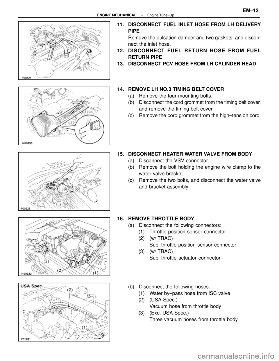
11. DISCONNECT FUEL INLET HOSE FROM LH DELIVERYPIPE
Remove the pulsation damper and two gaskets, and discon-
nect the inlet hose.
12. D I S C O N N E C T F U E L R E T U R N H O S E F R O M F U E L RETURN PIPE
13. DISCONNECT PCV HOSE FROM LH CYLINDER HEAD
14. REMOVE LH NO.3 TIMING BELT COVER (a) Remove the four mounting bolts.
(b) Disconnect the cord grommet from the timing belt cover,
and remove the timing belt cover.
(c) Remove the cord grommet from the high±tension cord.
15. DISCONNECT HEATER WATER VALVE FROM BODY (a) Disconnect the VSV connector.
(b) Remove the bolt holding the engine wire clamp to thewater valve bracket.
(c) Remove the two bolts, and disconnect the water valve and bracket assembly.
16. REMOVE THROTTLE BODY (a) Disconnect the following connectors:(1) Throttle position sensor connector
(2) (w/ TRAC)
Sub±throttle position sensor connector
(3) (w/ TRAC) Sub±throttle actuator connector
(b) Disconnect the following hoses: (1) Water by±pass hose from ISC valve
(2) (USA Spec.) Vacuum hose from throttle body
(3) (Exc. USA Spec.) Three vacuum hoses from throttle body
±
ENGINE MECHANICAL Engine Tune±UpEM±13
WhereEverybodyKnowsYourName
Page 2215 of 4087
16. REMOVE LH CYLINDER HEAD COVER(a) Remove the two bolts holding the high±tension cordclamp to the cylinder head.
(b) Disc onnect the high±tension cords from the spark
plugs.
(c) Disconnect the high±tension cords from the front high±tension cord clamp.
(d) Disconnect the engine wire from the two wire clamps on
the LH delivery pipe.
(e) Disconnect the four injector connectors.
(f) Disconnect the two engine wire connectors.
(g) Remove the eight bolts, seal washers, cylinder head
cover and gasket.
19. SET NO.1 CYLINDER TO TDC/COMPRESSION (a) Turn the crankshaft pulley, and align its groove with thetiming mark º0º of the No.1 timing belt cover.
±
ENGINE MECHANICAL Engine Tune±UpEM±15
WhereEverybodyKnowsYourName