Page 1730 of 4087
37. INSTALL A/C COMPRESSOR(a) In sta ll th e A/C co mp re sso r, co mp re sso r sta y an dground cable with the three bolts and nut.
Torque: Bolt 49 N Vm (500 kgf Vcm, 36 ft Vlbf)
Nut 29 N Vm (300 kgf Vcm, 22 ft Vlbf)
(b) Connect the A/C compressor connector.
38. INSTALL RADIATOR AND RESERVOIR TANK (See steps 25 and 26 on pages EM±174 to 175)
39. INSTALL DRIVE BELT Install the drive belt by turning the drive belt tensioner coun-
terclockwise.
HINT: The pully bolt for the belt tensioner has a lefthand
thread.
40. INSTALL BATTERY
41. FILL WITH ENGINE COOLANT (See page CO±7)
42. CHECK IGNITION TIMING (See page IG±28)
Ignition timing:
8±125 BTDC @ idle
(w/ Terminals TE1 and E1 connected)
43. INSTALL ENGINE UNDER COVER
±
ENGINE MECHANICAL Timing BeltEM±57
WhereEverybodyKnowsYourName
Page 1733 of 4087
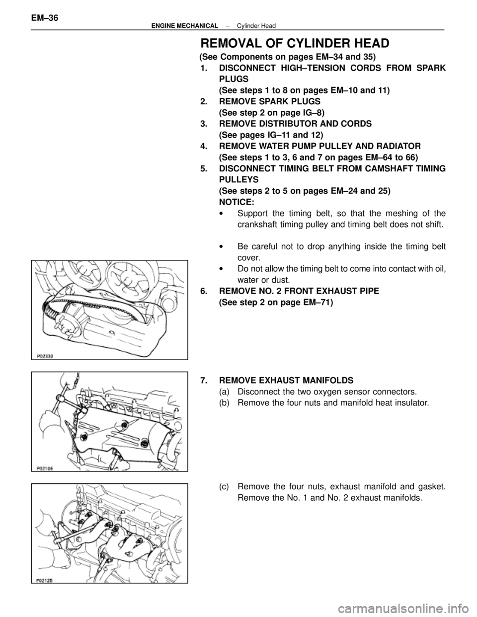
REMOVAL OF CYLINDER HEAD
(See Components on pages EM±34 and 35)1. DISCONNECT HIGH±TENSION CORDS FROM SPARK PLUGS
(See steps 1 to 8 on pages EM±10 and 11)
2. REMOVE SPARK PLUGS (See step 2 on page IG±8)
3. REMOVE DISTRIBUTOR AND CORDS
(See pages IG±11 and 12)
4. REMOVE WATER PUMP PULLEY AND RADIATOR (See steps 1 to 3, 6 and 7 on pages EM±64 to 66)
5. DISCONNECT TIMING BELT FROM CAMSHAFT TIMING PULLEYS
(See steps 2 to 5 on pages EM±24 and 25)
NOTICE:
wSupport the timing belt, so that the meshing of the
crankshaft timing pulley and timing belt does not shift.
w Be careful not to drop anything inside the timing belt
cover.
w Do not allow the timing belt to come into contact with oil,
water or dust.
6. REMOVE NO. 2 FRONT EXHAUST PIPE (See step 2 on page EM±71)
7. REMOVE EXHAUST MANIFOLDS (a) Disconnect the two oxygen sensor connectors.
(b) Remove the four nuts and manifold heat insulator.
(c) Remove the four nuts, exhaust manifold and gasket.Remove the No. 1 and No. 2 exhaust manifolds.
EM±36
±
ENGINE MECHANICAL Cylinder Head
WhereEverybodyKnowsYourName
Page 1736 of 4087
17. REMOVE NO. 3, No. 1 AND NO. 2 CYLINDER HEADCOVERS
(a) Remove the 12 bolts and four nuts.
(b) Remove the cylinder head covers and gaskets.
18. REMOVE CAMSHAFT TIMING PULLEYS Hold the hexagon portion of the camshaft with a wrench, and
remove the pulley mount bolt and camshaft pulley.
19. REMOVE NO. 4 TIMING BELT COVER Remove the four bolts and timing belt cover.
20. REMOVE CAMSHAFTS (a) Uniformly loosen and remove the four bearing cap bolts.
(b) Using a screwdriver, pry out the two No. 1 camshaft bearing caps and oil seals.
NOTICE: Be careful not to damage the cap. Tape the
screwdriver tip.
±
ENGINE MECHANICAL Cylinder HeadEM±39
WhereEverybodyKnowsYourName
Page 1755 of 4087
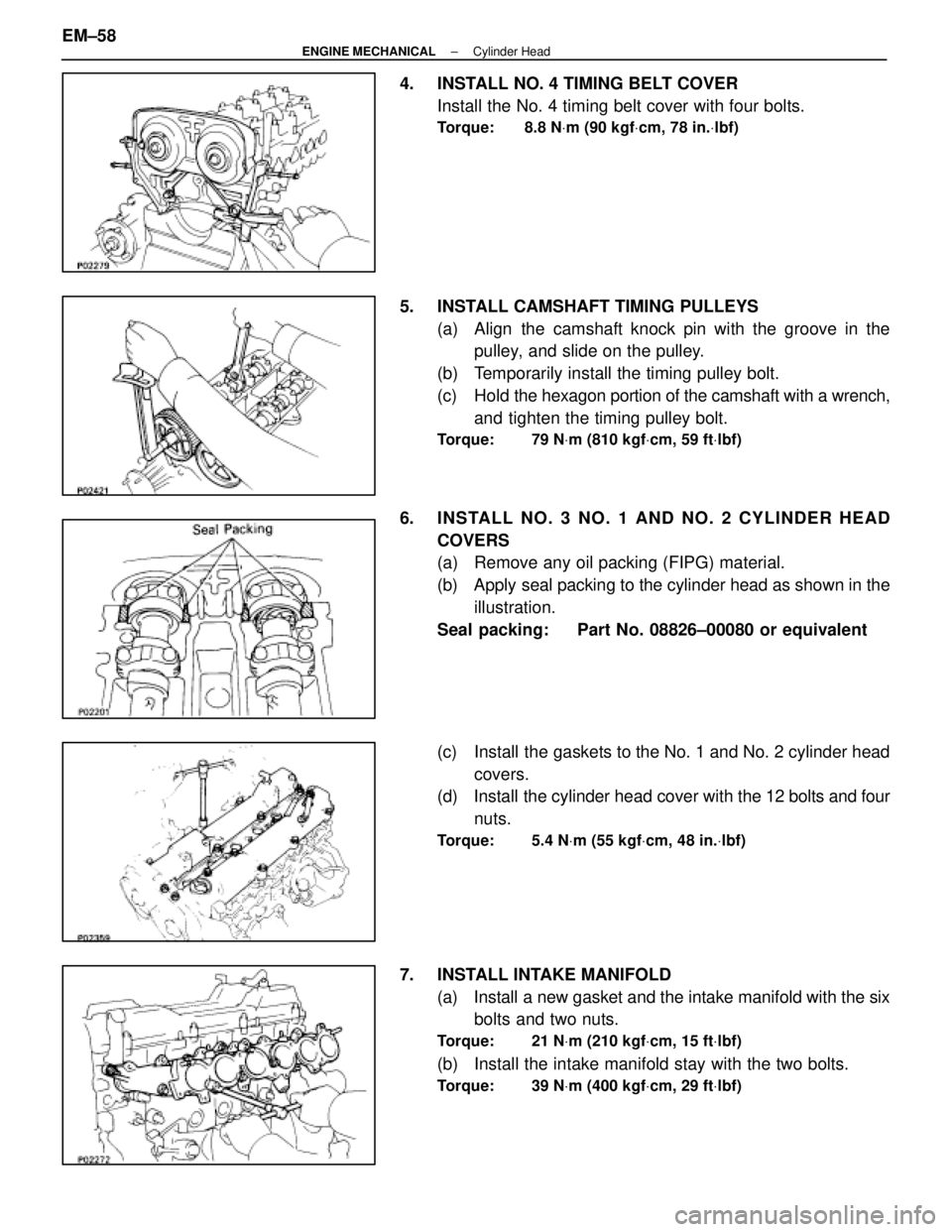
4. INSTALL NO. 4 TIMING BELT COVERInstall the No. 4 timing belt cover with four bolts.
Torque: 8.8 N Vm (90 kgf Vcm, 78 in. Vlbf)
5. INSTALL CAMSHAFT TIMING PULLEYS
(a) Align the camshaft knock pin with the groove in thepulley, and slide on the pulley.
(b) Temporarily install the timing pulley bolt.
(c) Hold the hexagon portion of the camshaft with a wrench,
and tighten the timing pulley bolt.
Torque: 79 N Vm (810 kgf Vcm, 59 ft Vlbf)
6. INS TALL NO . 3 NO . 1 AND NO . 2 CY LINDE R HE AD
COVERS
(a) Remove any oil packing (FIPG) material.
(b) Apply seal packing to the cylinder head as shown in theillustration.
Seal packing: Part No. 08826±00080 or equivalent
(c) Install the gaskets to the No. 1 and No. 2 cylinder head covers.
(d) Install the cylinder head cover with the 12 bolts and four
nuts.
Torque: 5.4 N Vm (55 kgf Vcm, 48 in. Vlbf)
7. INSTALL INTAKE MANIFOLD
(a) Install a new gasket and the intake manifold with the sixbolts and two nuts.
Torque: 21 N Vm (210 kgf Vcm, 15 ft Vlbf)
(b) Install the intake manifold stay with the two bolts.
Torque: 39 N Vm (400 kgf Vcm, 29 ft Vlbf)
EM±58±
ENGINE MECHANICAL Cylinder Head
WhereEverybodyKnowsYourName
Page 1758 of 4087
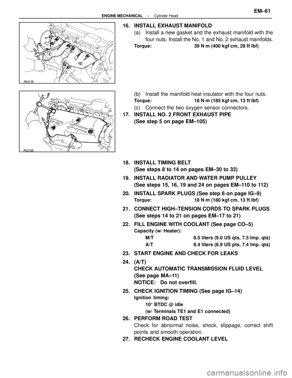
16. INSTALL EXHAUST MANIFOLD(a) Install a new gasket and the exhaust manifold with thefour nuts. Install the No. 1 and No. 2 exhaust manifolds.
Torque: 39 N Vm (400 kgf Vcm, 29 ft Vlbf)
(b) Install the manifold heat insulator with the four nuts.
Torque: 18 N Vm (185 kgf Vcm, 13 ft Vlbf)
(c) Connect the two oxygen sensor connectors.
17. INSTALL NO. 2 FRONT EXHAUST PIPE (See step 5 on page EM±105)
18. INSTALL TIMING BELT (See steps 8 to 14 on pages EM±30 to 33)
19. INSTALL RADIATOR AND WATER PUMP PULLEY (See steps 15, 16, 19 and 24 on pages EM±110 to 112)
20. INSTALL SPARK PLUGS (See step 6 on page IG±9)
Torque: 18 N Vm (180 kgf Vcm, 13 ft Vlbf)
21. CONNECT HIGH±TENSION CORDS TO SPARK PLUGS
(See steps 14 to 21 on pages EM±17 to 21)
22. FILL ENGINE WITH COOLANT (See page CO±5)
Capacity (w/ Heater): M/T 8.5 liters (9.0 US qts, 7.5 lmp. qts)
A/T 8.4 liters (8.9 US pts, 7.4 lmp. qts)
23. START ENGINE AND CHECK FOR LEAKS
24. (A/T)CHECK AUTOMATIC TRANSMISSION FLUID LEVEL
(See page MA±11)
NOTICE: Do not overfill.
25. CHECK IGNITION TIMING (See page IG±14)
Ignition timing: 105 BTDC @ idle
(w/ Terminals TE1 and E1 connected)
26. PERFORM ROAD TEST Check for abnormal noise, shock, slippage, correct shift
points and smooth operation.
27. RECHECK ENGINE COOLANT LEVEL
±
ENGINE MECHANICAL Cylinder HeadEM±61
WhereEverybodyKnowsYourName
Page 1761 of 4087
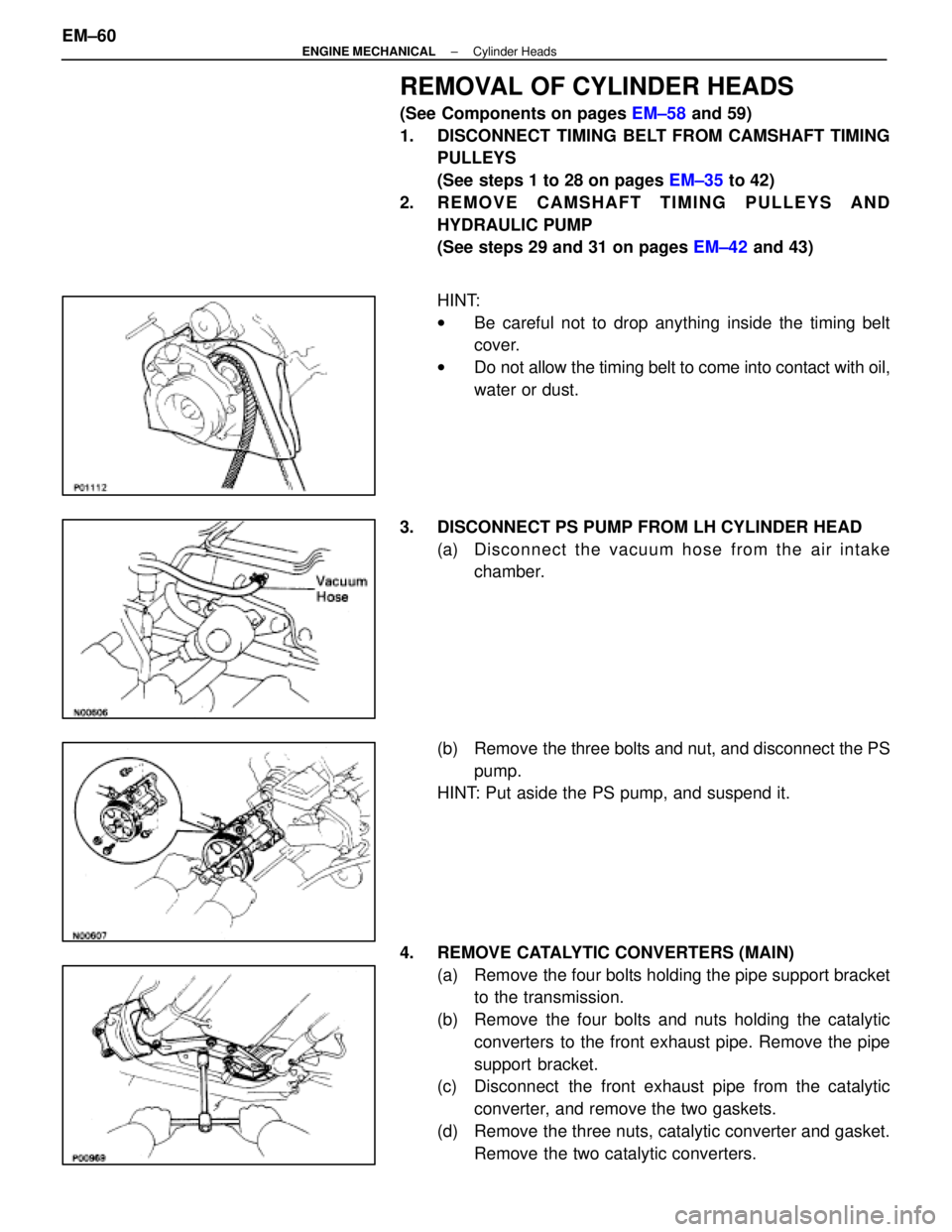
REMOVAL OF CYLINDER HEADS
(See Components on pages EM±58 and 59)
1. DISCONNECT TIMING BELT FROM CAMSHAFT TIMING PULLEYS
(See steps 1 to 28 on pages EM±35 to 42)
2. REMOVE CAMSHAFT TIMING PULLEYS AND HYDRAULIC PUMP
(See steps 29 and 31 on pages EM±42 and 43)
HINT:
w Be careful not to drop anything inside the timing belt
cover.
w Do not allow the timing belt to come into contact with oil,
water or dust.
3. DISCONNECT PS PUMP FROM LH CYLINDER HEAD (a) Disc onnect the vacuum hose from the air intake
chamber.
(b) Remove the three bolts and nut, and disconnect the PS pump.
HINT: Put aside the PS pump, and suspend it.
4. REMOVE CATALYTIC CONVERTERS (MAIN) (a) Remove the four bolts holding the pipe support bracketto the transmission.
(b) Remove the four bolts and nuts holding the catalytic converters to the front exhaust pipe. Remove the pipe
support bracket.
(c) Disconnect the front exhaust pipe from the catalytic
converter, and remove the two gaskets.
(d) Remove the three nuts, catalytic converter and gasket. Remove the two catalytic converters.
EM±60
±
ENGINE MECHANICAL Cylinder Heads
WhereEverybodyKnowsYourName
Page 1763 of 4087
9. REMOVE TIMING BELT REAR PLATESRemove the two bolts and rear plate. Remove the two rear
plates.
10. REMOVE VACUUM PIPE (a) Disconnect the following hoses:(1) (USA Spec.)
Vacuum hose from throttle body
(2) (Exc. USA Spec.) Three vacuum hoses from throttle body
(3) Vacuum hose from fuel pressure regulator
(4) Two vacuum hoses from VSV for fuel pressure con-
trol system
(5) (Exc. USA Spec.) Two vacuum hoses from EGR vacuum modulator
(6) Two vacuum hoses (from VSV for EVAP system)
from vacuum pipe
(7) Vacuum hose (from VSV for fuel pressure control system) from air intake chamber
(8) Vacuum hose (from charcoal canister) from vacu-
um pipe.
(b) Remove the two bolts, the vacuum pipe and vacuum hoses assembly.
EM±62
±
ENGINE MECHANICAL Cylinder Heads
WhereEverybodyKnowsYourName
Page 1814 of 4087
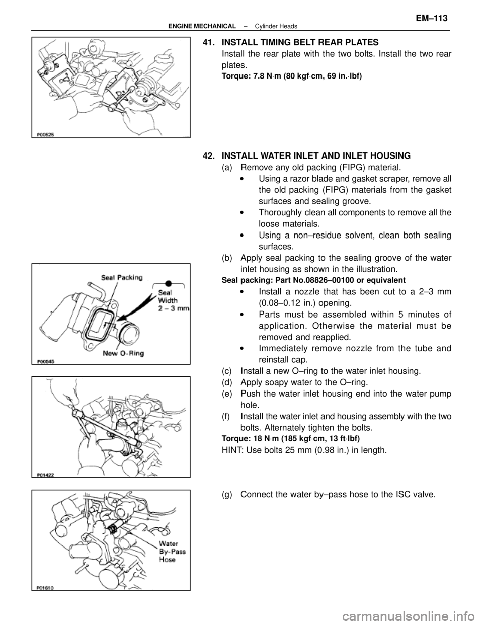
41. INSTALL TIMING BELT REAR PLATESInstall the rear plate with the two bolts. Install the two rear
plates.
Torque: 7.8 N Vm (80 kgf Vcm, 69 in. Vlbf)
42. INSTALL WATER INLET AND INLET HOUSING
(a) Remove any old packing (FIPG) material.w Using a razor blade and gasket scraper, remove all
the old packing (FIPG) materials from the gasket
surfaces and sealing groove.
w Thoroughly clean all components to remove all the
loose materials.
w Using a non±residue solvent, clean both sealing
surfaces.
(b) Apply seal packing to the sealing groove of the water inlet housing as shown in the illustration.
Seal packing: Part No.08826±00100 or equivalent
w Install a nozzle that has been cut to a 2±3 mm
(0.08±0.12 in.) opening.
w Parts must be assembled within 5 minutes of
application. Otherwise the material must be
removed and reapplied.
w Immediately remove nozzle from the tube and
reinstall cap.
(c) Install a new O±ring to the water inlet housing.
(d) Apply soapy water to the O±ring.
(e) Push the water inlet housing end into the water pump hole.
(f) Install the water inlet and housing assembly with the two
bolts. Alternately tighten the bolts.
Torque: 18 N Vm (185 kgf Vcm, 13 ft Vlbf)
HINT: Use bolts 25 mm (0.98 in.) in length.
(g) Connect the water by±pass hose to the ISC valve.
±
ENGINE MECHANICAL Cylinder HeadsEM±113
WhereEverybodyKnowsYourName