Page 2374 of 4087
24. CONNECT IGNITER CONNECTOR(a) Connect the two igniter connectors.
(b) Install the wire clamp.
25. INSTALL RADIATOR (a) Install the two lower radiator supports to the radiator.
(b) Place the radiator on the body bracket.
(c) Slightly lift the radiator, and connect the two cooler hose(for cooling fan) to the hose clamp on the radiator fan
shrould.
(d) Install the upper radiator support with the two bolts and screw. Install the two upper radiator supports.
(e) Connect the following hoses: (1) Pressure hose to hydraulic pump
(2) Suction hose to hydraulic pump
EM±174
±
ENGINE MECHANICAL Cylinder Block
WhereEverybodyKnowsYourName
Page 2375 of 4087
(3) Two oil cooler hoses (for A/T) to radiator
(4) Two radiator hoses
(5) Two oil cooler hoses (for cooling fan) to pipes
(f) Connect the water temperature sensor connector.
(g) Install the wire clamp (for water temperature sensor) to the radiator fan shrould.
26. INSTALL RADIATOR RESERVOIR TANK (a) Install the reservoir tank to the reservoir tank bracket.
(b) Install the reservoir tank bracket with the two bolts.
±
ENGINE MECHANICAL Cylinder BlockEM±175
WhereEverybodyKnowsYourName
Page 2376 of 4087

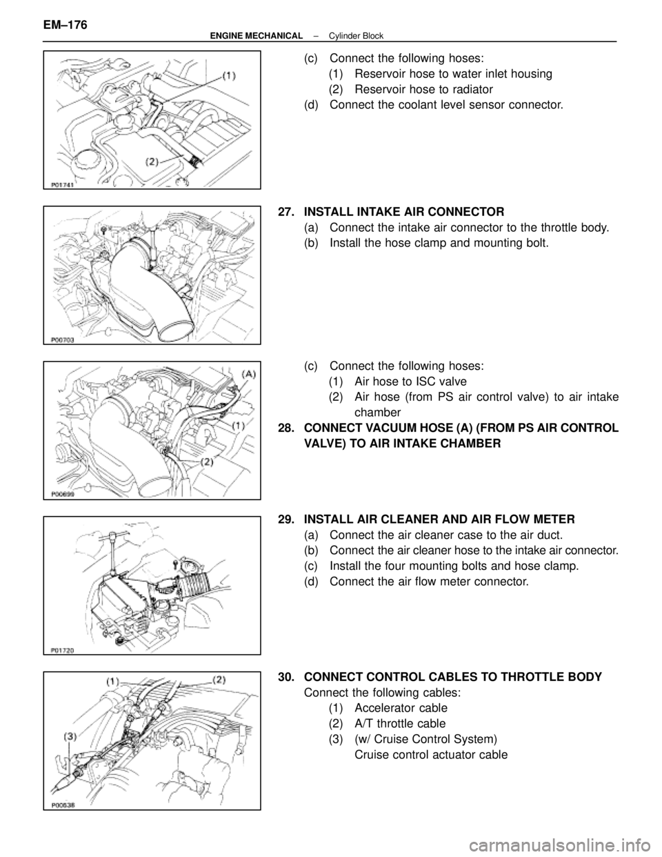
(c) Connect the following hoses:(1) Reservoir hose to water inlet housing
(2) Reservoir hose to radiator
(d) Connect the coolant level sensor connector.
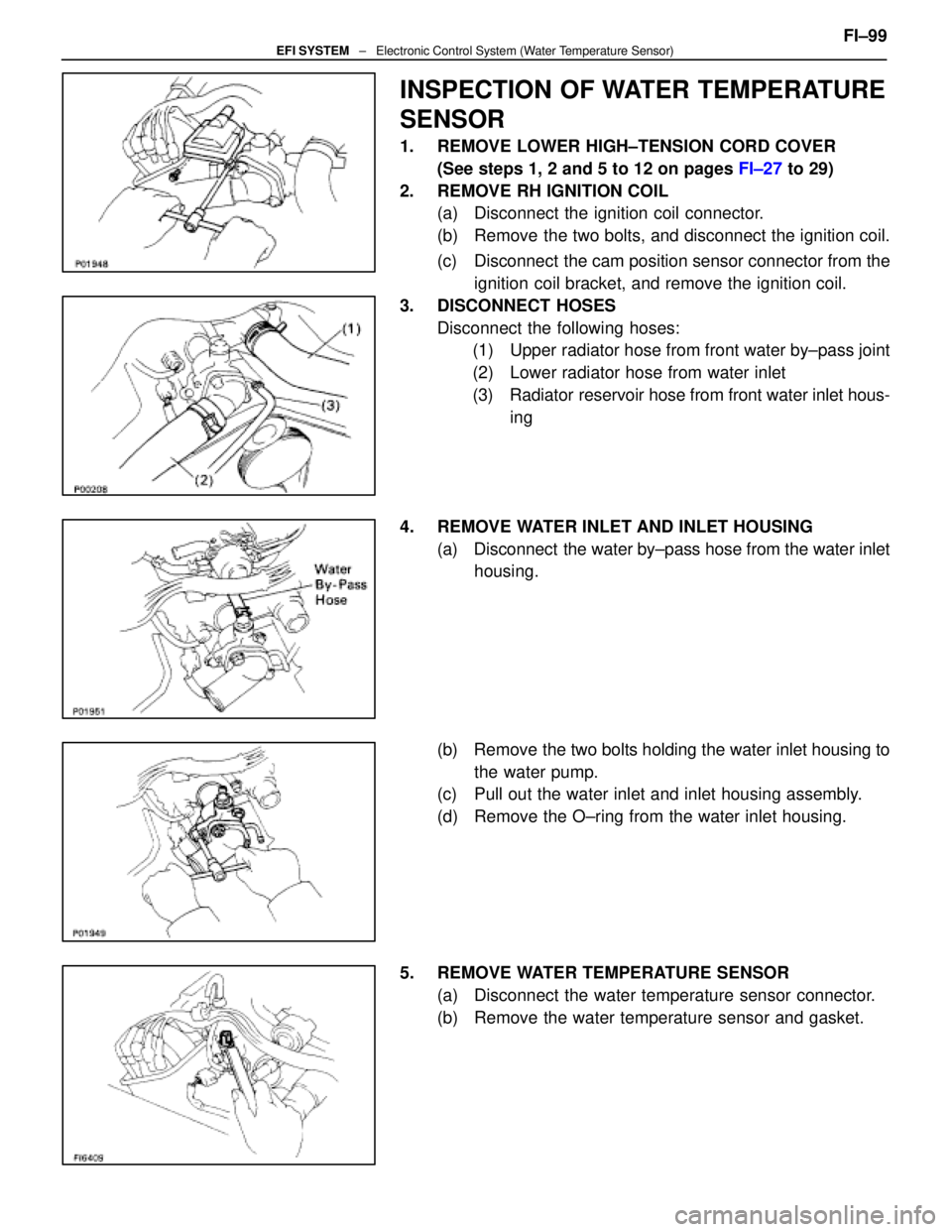
27. INSTALL INTAKE AIR CONNECTOR (a) Connect the intake air connector to the throttle body.
(b) Install the hose clamp and mounting bolt.
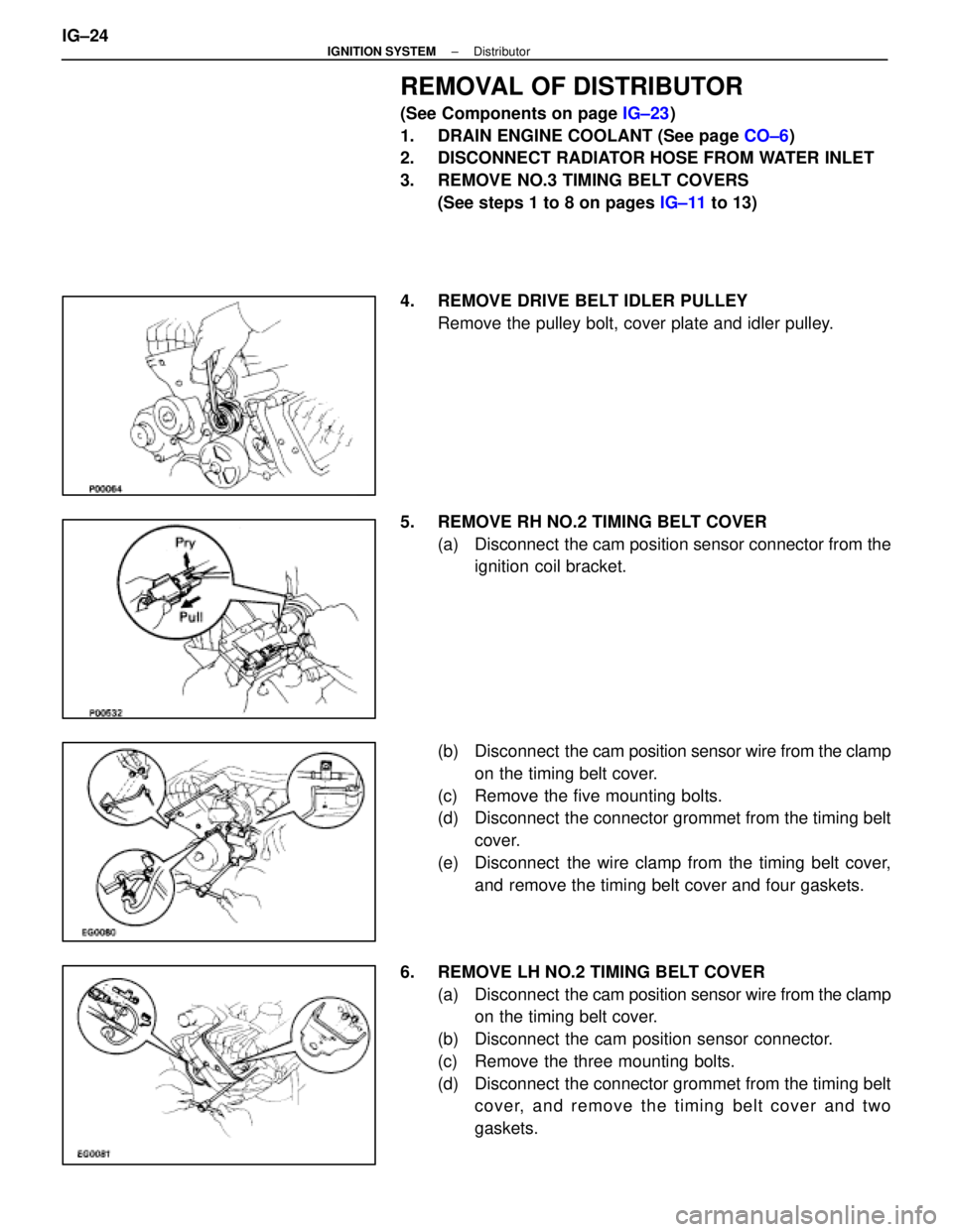
(c) Connect the following hoses:(1) Air hose to ISC valve
(2) Air hose (from PS air control valve) to air intake chamber
28. CONNECT VACUUM HOSE (A) (FROM PS AIR CONTROL VALVE) TO AIR INTAKE CHAMBER
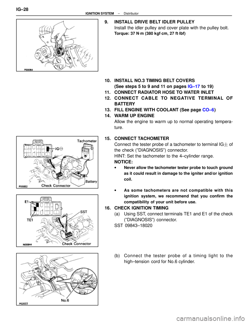
29. INSTALL AIR CLEANER AND AIR FLOW METER (a) Connect the air cleaner case to the air duct.
(b) Connect the air cleaner hose to the intake air connector.
(c) Install the four mounting bolts and hose clamp.
(d) Connect the air flow meter connector.
30. CONNECT CONTROL CABLES TO THROTTLE BODY Connect the following cables:(1) Accelerator cable
(2) A/T throttle cable
(3) (w/ Cruise Control System)
Cruise control actuator cable
EM±176
±
ENGINE MECHANICAL Cylinder Block
WhereEverybodyKnowsYourName
Page 2479 of 4087

INSPECTION OF WATER TEMPERATURE
SENSOR
1. REMOVE LOWER HIGH±TENSION CORD COVER(See steps 1, 2 and 5 to 12 on pages FI±27 to 29)
2. REMOVE RH IGNITION COIL (a) Disconnect the ignition coil connector.
(b) Remove the two bolts, and disconnect the ignition coil.
(c) Disconnect the cam position sensor connector from the
ignition coil bracket, and remove the ignition coil.
3. DISCONNECT HOSES Disconnect the following hoses:(1) Upper radiator hose from front water by±pass joint
(2) Lower radiator hose from water inlet
(3) Radiator reservoir hose from front water inlet hous-
ing
4. REMOVE WATER INLET AND INLET HOUSING (a) Disconnect the water by±pass hose from the water inlethousing.
(b) Remove the two bolts holding the water inlet housing to the water pump.
(c) Pull out the water inlet and inlet housing assembly.
(d) Remove the O±ring from the water inlet housing.
5. REMOVE WATER TEMPERATURE SENSOR (a) Disconnect the water temperature sensor connector.
(b) Remove the water temperature sensor and gasket. FI±99
EFI SYSTEM
± Electronic Control System (Water Temperature Sensor)
WhereEverybodyKnowsYourName
Page 2481 of 4087
(e) Push in the water inlet housing end into the water pumphole.
(f) Install the water inlet and inlet housing assembly with
the two bolts. Alternately tighten the bolts.
Torque: 18 N Vm (185 kgf Vcm, 13 ft Vlbf)
(g) Connect the water by±pass hose to the water inlet
housing.
9. RECONNECT HOSES Connect the following hoses:(1) Upper radiator hose to front water by±pass joint
(2) Lower radiator hose to water inlet
(3) Radiator reservoir hose to front water inlet housing
10. REINSTALL RH IGNITION COIL (a) Install the ignition coil with the two bolts.
(b) Install the cam position sensor connector to the ignitioncoil bracket.
(c) Connect the ignition coil connector.
11. REINSTALL LOWER HIGH±TENSION CORD COVER (See steps 1 to 13 and 16 to 18 on pages FI±39 to 41)FI±101
EFI SYSTEM
± Electronic Control System (Water Temperature Sensor)
WhereEverybodyKnowsYourName
Page 2546 of 4087

REMOVAL OF DISTRIBUTOR
(See Components on page IG±23)
1. DRAIN ENGINE COOLANT (See page CO±6)
2. DISCONNECT RADIATOR HOSE FROM WATER INLET
3. REMOVE NO.3 TIMING BELT COVERS
(See steps 1 to 8 on pages IG±11 to 13)
4. REMOVE DRIVE BELT IDLER PULLEY Remove the pulley bolt, cover plate and idler pulley.
5. REMOVE RH NO.2 TIMING BELT COVER (a) Disconnect the cam position sensor connector from theignition coil bracket.
(b) Disconnect the cam position sensor wire from the clamp
on the timing belt cover.
(c) Remove the five mounting bolts.
(d) Disconnect the connector grommet from the timing belt cover.
(e) Disconnect the wire clamp from the timing belt cover, and remove the timing belt cover and four gaskets.
6. REMOVE LH NO.2 TIMING BELT COVER (a) Disconnect the cam position sensor wire from the clamp
on the timing belt cover.
(b) Disconnect the cam position sensor connector.
(c) Remove the three mounting bolts.
(d) Disconnect the connector grommet from the timing belt cover, and remove the timing belt cover and two
gaskets.
IG±24
±
IGNITION SYSTEM Distributor
WhereEverybodyKnowsYourName
Page 2550 of 4087

9. INSTALL DRIVE BELT IDLER PULLEYInstall the idler pulley and cover plate with the pulley bolt.
Torque: 37 N Vm (380 kgf Vcm, 27 ft Vlbf)
10. INSTALL NO.3 TIMING BELT COVERS
(See steps 5 to 9 and 11 on pages IG±17 to 19)
11. CONNECT RADIATOR HOSE TO WATER INLET
12. C O N N E C T C A B L E TO N E G AT I V E T E R M I N A L O F BATTERY
13. FILL ENGINE WITH COOLANT (See page CO±6)
14. WARM UP ENGINE Allow the engine to warm up to normal operating tempera-
ture.
15. CONNECT TACHOMETER Connect the tester probe of a tachometer to terminal IG � of
the check (ºDIAGNOSISº) connector.
HINT: Set the tachometer to the 4±cylinder range.
NOTICE:
w Never allow the tachometer tester probe to touch ground
as it could result in damage to the igniter and/or ignition
coil.
w As some tachometers are not compatible with this
ignition system, we recommend that you confirm the
compatibility of your unit before use.
16. CHECK IGNITION TIMING
(a) Using SST, connect terminals TE1 and E1 of the check(ºDIAGNOSISº) connector.
SST 09843±18020
(b) C onnect the tester probe of a timing light to the
high±tension cord for No.6 cylinder.
IG±28
±
IGNITION SYSTEM Distributor
WhereEverybodyKnowsYourName
Page 2787 of 4087
DESCRIPTION
This engine utilizes a pressurized forced circulation cooling system which i\
ncludes a hermostat equipped
with a by±pass valve mounted on the inlet side. The cooling system is composed of the water jacket (inside the cylinder bl\
ock and cylinderhead), radiator,
water pump, thermostat, cooling fan, hoses and other components.
OPERATION
CO±2±
COOLIING SYSTEM Description
WhereEverybodyKnowsYourName