Page 2112 of 4087

REMOVAL OF DISTRIBUTOR
(See Components on page IG±23)
1. DRAIN ENGINE COOLANT (See page CO±6)
2. DISCONNECT RADIATOR HOSE FROM WATER INLET
3. REMOVE NO.3 TIMING BELT COVERS
(See steps 1 to 8 on pages IG±11 to 13)
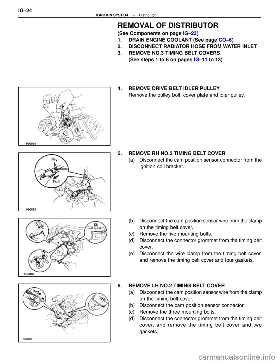
4. REMOVE DRIVE BELT IDLER PULLEY Remove the pulley bolt, cover plate and idler pulley.
5. REMOVE RH NO.2 TIMING BELT COVER (a) Disconnect the cam position sensor connector from theignition coil bracket.
(b) Disconnect the cam position sensor wire from the clamp
on the timing belt cover.
(c) Remove the five mounting bolts.
(d) Disconnect the connector grommet from the timing belt cover.
(e) Disconnect the wire clamp from the timing belt cover, and remove the timing belt cover and four gaskets.
6. REMOVE LH NO.2 TIMING BELT COVER (a) Disconnect the cam position sensor wire from the clamp
on the timing belt cover.
(b) Disconnect the cam position sensor connector.
(c) Remove the three mounting bolts.
(d) Disconnect the connector grommet from the timing belt cover, and remove the timing belt cover and two
gaskets.
IG±24
±
IGNITION SYSTEM Distributor
WhereEverybodyKnowsYourName
Page 2116 of 4087

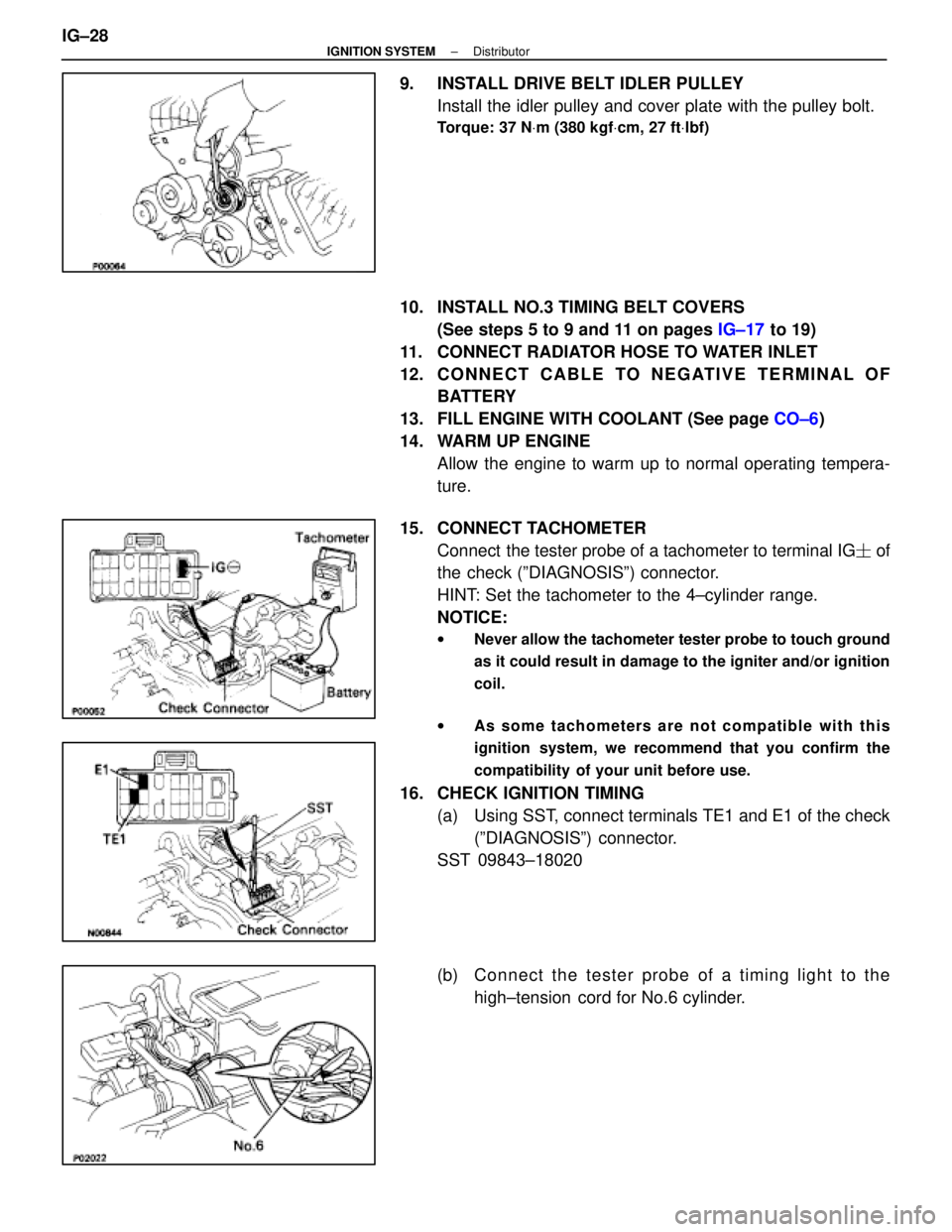
9. INSTALL DRIVE BELT IDLER PULLEYInstall the idler pulley and cover plate with the pulley bolt.
Torque: 37 N Vm (380 kgf Vcm, 27 ft Vlbf)
10. INSTALL NO.3 TIMING BELT COVERS
(See steps 5 to 9 and 11 on pages IG±17 to 19)
11. CONNECT RADIATOR HOSE TO WATER INLET
12. C O N N E C T C A B L E TO N E G AT I V E T E R M I N A L O F BATTERY
13. FILL ENGINE WITH COOLANT (See page CO±6)
14. WARM UP ENGINE Allow the engine to warm up to normal operating tempera-
ture.
15. CONNECT TACHOMETER Connect the tester probe of a tachometer to terminal IG � of
the check (ºDIAGNOSISº) connector.
HINT: Set the tachometer to the 4±cylinder range.
NOTICE:
w Never allow the tachometer tester probe to touch ground
as it could result in damage to the igniter and/or ignition
coil.
w As some tachometers are not compatible with this
ignition system, we recommend that you confirm the
compatibility of your unit before use.
16. CHECK IGNITION TIMING
(a) Using SST, connect terminals TE1 and E1 of the check(ºDIAGNOSISº) connector.
SST 09843±18020
(b) C onnect the tester probe of a timing light to the
high±tension cord for No.6 cylinder.
IG±28
±
IGNITION SYSTEM Distributor
WhereEverybodyKnowsYourName
Page 2171 of 4087

19. BRAKE PEDAL
(a) Check that pedal for smooth operation.
(b) Check that the pedal has the proper reservedistance and freeplay.
(c) Check the brake booster function.
20. BRAKES At a safe place, check that the brakes do not
pull to one side when applied.
21. PARKING BRAKE
(a) Check that the pedal has the proper travel.
(b) On a safe incline, check that the vehicle is held securely with only the parking brake applied.
22. A U TO M AT I C T RANSMISSION PARK
MECHANISM
(a) Check the lock release button of the selector lever for proper and smooth operation.
(b) On a safe incline, check that the vehicle is held securely with the selector lever in the ªPº
position and all brakes released.
MA00T±0A
UNDER HOOD
23. WINDSHIELD WASHER FLUIDCheck that there is sufficient fluid in the tank.
24. ENGINE COOLANT LEVEL
Check that the coolant level is between the
LEVEL lines on the see±through reservoir at
normal temperature (20 5C (68 5F)).
25. RADIATOR AND HOSES
(a) Check that the front of the radiator is clean and not blocked with leaves, dirt or bugs.
(b) Check the hoses for cracks, kinks, rot or loose connections.
26. BATTERY ELECTROLYTE LEVEL
Check the indicator.
When the indicator color is blue, the condition
is satisfactory. A red color indicates that dis-
tilled water must be added, and white indicates
that charging is necessary. 27. BRAKE FLUID LEVEL
Check that the brake fluid level is near the up-
per level line on the see±through reservoir.
28. ENGINE DRIVE BELT Check drive belt for fraying, cracks, wear or oili-
ness.
29. ENGINE OIL LEVEL
Check that level on the dipstick with the engine
turned off.
30. POWER STEERING FLUID LEVEL Check the level on the dipstick.
The level should be in the ªHOTº or ªCOLDº
range depending on the fluid temperature.
31. AUTOMATIC TRANSMISSION FLUID LEVEL
(a) Park the vehicle on a level surface.
(b) With the engine idling and the parking and foot brake applied, shift the selector into all
positions from ªPº to ªLº, and then shift into ªPº.
(c) Turn and pull out the dipstick and wipe off the fluid with a clean rag.
Re±insert the dipstick fully and check that the
fluid level is in the ªHOTº range.
(d) Perform this check with the fluid at normal driving temperature (70 ± 80 �C (158 ± 176 �F)).
If the level is at the low side, add fluid.
NOTICE: Do not overfill.
HINT: Wait about 30 minutes before checking
the fluid level after extended driving at high
speeds in hot weather, driving in heavy traffic
or with a trailer.
32. EXHAUST SYSTEM Visually inspect for cracks, holes or loose sup-
ports.
If any change in the sound of the exhaust or
smell of the exhaust fumes is noticed, have the
cause located and corrected.
MA±20
±
MAINTENANCE (1UZ ± FE)
WhereEverybodyKnowsYourName
Page 2208 of 4087

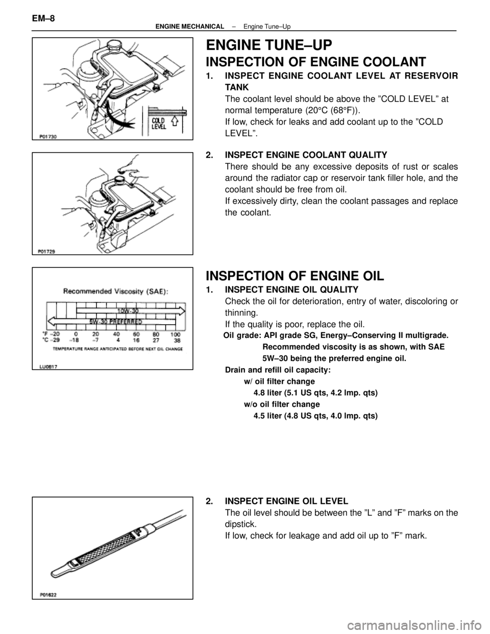
ENGINE TUNE±UP
INSPECTION OF ENGINE COOLANT
1. INSPECT ENGINE COOLANT LEVEL AT RESERVOIRTANK
The coolant level should be above the ºCOLD LEVELº at
normal temperature (20 5C (68 5F)).
If low, check for leaks and add coolant up to the ºCOLD
LEVELº.
2. INSPECT ENGINE COOLANT QUALITY There should be any excessive deposits of rust or scales
around the radiator cap or reservoir tank filler hole, and the
coolant should be free from oil.
If excessively dirty, clean the coolant passages and replace
the coolant.
INSPECTION OF ENGINE OIL
1. INSPECT ENGINE OIL QUALITYCheck the oil for deterioration, entry of water, discoloring or
thinning.
If the quality is poor, replace the oil.
Oil grade: API grade SG, Energy±Conserving II multigrade.
Recommended viscosity is as shown, with SAE
5W±30 being the preferred engine oil.
Drain and refill oil capacity: w/ oil filter change4.8 liter (5.1 US qts, 4.2 lmp. qts)
w/o oil filter change 4.5 liter (4.8 US qts, 4.0 lmp. qts)
2. INSPECT ENGINE OIL LEVEL The oil level should be between the ºLº and ºFº marks on the
dipstick.
If low, check for leakage and add oil up to ºFº mark.
EM±8
±
ENGINE MECHANICAL Engine Tune±Up
WhereEverybodyKnowsYourName
Page 2235 of 4087

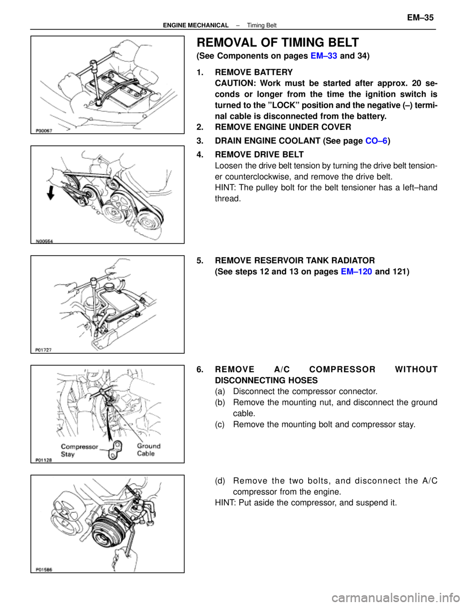
REMOVAL OF TIMING BELT
(See Components on pages EM±33 and 34)
1. REMOVE BATTERY CAUTION: Work must be started after approx. 20 se-
conds or longer from the time the ignition switch is
turned to the ºLOCKº position and the negative (±) termi-
nal cable is disconnected from the battery.
2. REMOVE ENGINE UNDER COVER
3. DRAIN ENGINE COOLANT (See page CO±6)
4. REMOVE DRIVE BELT Loosen the drive belt tension by turning the drive belt tension-
er counterclockwise, and remove the drive belt.
HINT: The pulley bolt for the belt tensioner has a left±hand
thread.
5. REMOVE RESERVOIR TANK RADIATOR (See steps 12 and 13 on pages EM±120 and 121)
6. REMOVE A/C COMPRESSOR WITHOUT DISCONNECTING HOSES
(a) Disconnect the compressor connector.
(b) Remove the mounting nut, and disconnect the groundcable.
(c) Remove the mounting bolt and compressor stay.
(d) R e m o v e t h e t w o b o l t s , a n d d i s c onnect the A/C
compressor from the engine.
HINT: Put aside the compressor, and suspend it.
±
ENGINE MECHANICAL Timing BeltEM±35
WhereEverybodyKnowsYourName
Page 2257 of 4087
37. INSTALL A/C COMPRESSOR(a) In sta ll th e A/C co mp re sso r, co mp re sso r sta y an dground cable with the three bolts and nut.
Torque: Bolt 49 N Vm (500 kgf Vcm, 36 ft Vlbf)
Nut 29 N Vm (300 kgf Vcm, 22 ft Vlbf)
(b) Connect the A/C compressor connector.
38. INSTALL RADIATOR AND RESERVOIR TANK (See steps 25 and 26 on pages EM±174 to 175)
39. INSTALL DRIVE BELT Install the drive belt by turning the drive belt tensioner coun-
terclockwise.
HINT: The pully bolt for the belt tensioner has a lefthand
thread.
40. INSTALL BATTERY
41. FILL WITH ENGINE COOLANT (See page CO±7)
42. CHECK IGNITION TIMING (See page IG±28)
Ignition timing:
8±125 BTDC @ idle
(w/ Terminals TE1 and E1 connected)
43. INSTALL ENGINE UNDER COVER
±
ENGINE MECHANICAL Timing BeltEM±57
WhereEverybodyKnowsYourName
Page 2320 of 4087
12. REMOVE RADIATOR RESERVOIR TANK(a) Disconnect the coolant level sensor connector.
(b) Disconnect the following hoses:(1) Reservoir hose to water inlet housing
(2) Reservoir hose to radiator
(c) Remove the two bolts and reservoir tank bracket.
(d) Disconnect the reservoir tank from the reservoir tank bracket, and remove the reservoir tank.
13. REMOVE RADIATOR (a) Disconnect the water temperature sensor connector.
(b) Disc onnect the wire clamp (for water temperature
sensor) from the radiator fan shrould.
(c) Disconnect the following hoses: (1) Two oil cooler hoses (for cooling fan) from pipes
(2) Two radiator hoses
EM±120
±
ENGINE MECHANICAL Cylinder Block
WhereEverybodyKnowsYourName
Page 2321 of 4087
(3) Two oil cooler hoses (for A/T) from radiator Plug thehose ends.
(4) Suction hose from hydraulic pump
(5) Pressure hose from hydraulic pump
(c) Re mo ve th e two bo lts, scre w an d u pper radiator
support. Remove the two upper radiator supports.
(d) Slightly lift the radiator, and d isconnect the two oil cooler
hoses (for cooling fan) from the hose clamp on the
radiator fan shrould.
(e) Remove the radiator.
14. DISCONNECT IGNITER CONNECTORS (a) Disconnect the two igniter connectors.
(b) Disconnect the wire clamp from the body.
±
ENGINE MECHANICAL Cylinder BlockEM±121
WhereEverybodyKnowsYourName