Page 1640 of 4087
(3) Two oil cooler hoses (for A/T) to radiator
(4) Two radiator hoses
(5) Two oil cooler hoses (for cooling fan) to pipes
(f) Connect the water temperature sensor connector.
(g) Install the wire clamp (for water temperature sensor) to the radiator fan shrould.
26. INSTALL RADIATOR RESERVOIR TANK (a) Install the reservoir tank to the reservoir tank bracket.
(b) Install the reservoir tank bracket with the two bolts.
±
ENGINE MECHANICAL Cylinder BlockEM±175
WhereEverybodyKnowsYourName
Page 1641 of 4087
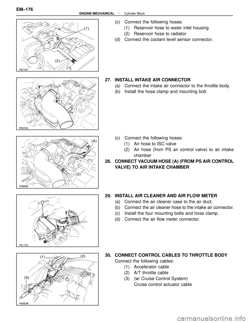
(c) Connect the following hoses:(1) Reservoir hose to water inlet housing
(2) Reservoir hose to radiator
(d) Connect the coolant level sensor connector.
27. INSTALL INTAKE AIR CONNECTOR (a) Connect the intake air connector to the throttle body.
(b) Install the hose clamp and mounting bolt.
(c) Connect the following hoses:(1) Air hose to ISC valve
(2) Air hose (from PS air control valve) to air intake chamber
28. CONNECT VACUUM HOSE (A) (FROM PS AIR CONTROL VALVE) TO AIR INTAKE CHAMBER
29. INSTALL AIR CLEANER AND AIR FLOW METER (a) Connect the air cleaner case to the air duct.
(b) Connect the air cleaner hose to the intake air connector.
(c) Install the four mounting bolts and hose clamp.
(d) Connect the air flow meter connector.
30. CONNECT CONTROL CABLES TO THROTTLE BODY Connect the following cables:(1) Accelerator cable
(2) A/T throttle cable
(3) (w/ Cruise Control System)
Cruise control actuator cable
EM±176
±
ENGINE MECHANICAL Cylinder Block
WhereEverybodyKnowsYourName
Page 1654 of 4087
ENGINE TUNE±UP
INSPECTION OF ENGINE COOLANT
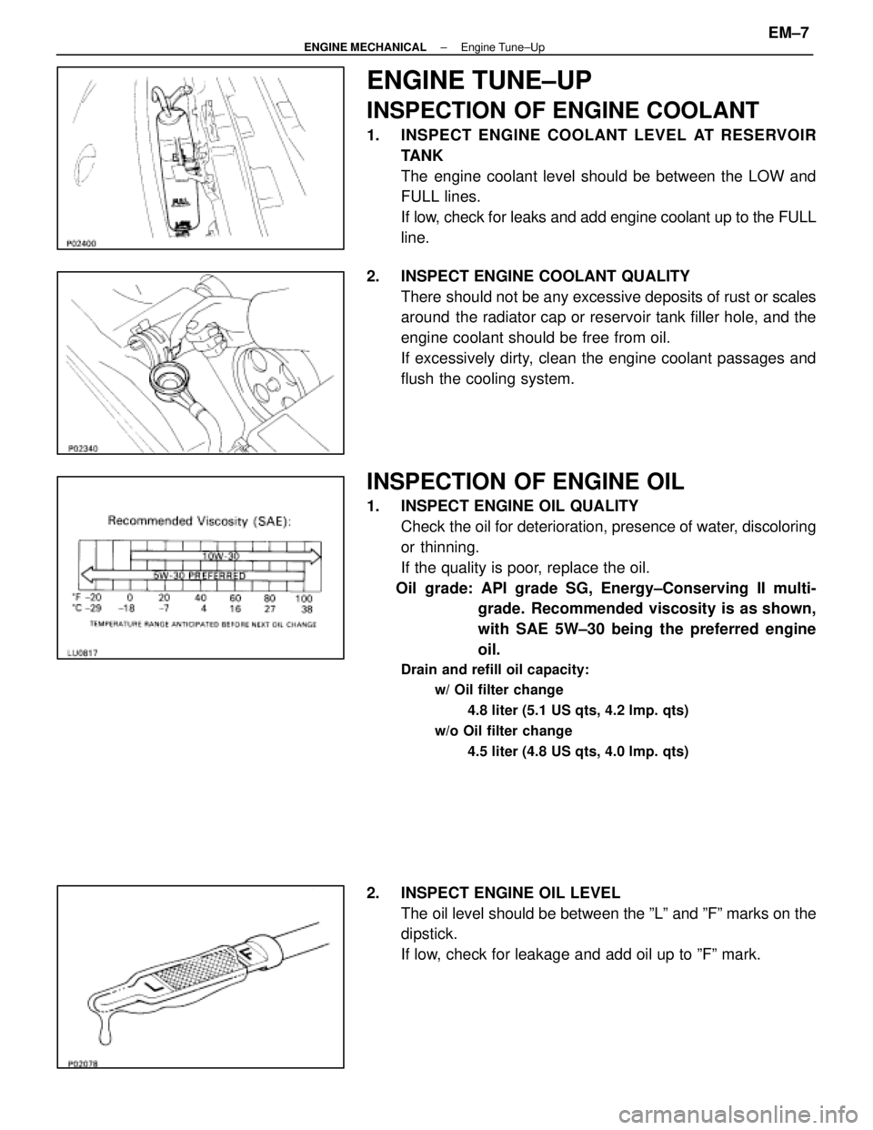
1. INSPECT ENGINE COOLANT LEVEL AT RESERVOIRTANK
The engine coolant level should be between the LOW and
FULL lines.
If low, check for leaks and add engine coolant up to the FULL
line.
2. INSPECT ENGINE COOLANT QUALITY There should not be any excessive deposits of rust or scales
around the radiator cap or reservoir tank filler hole, and the
engine coolant should be free from oil.
If excessively dirty, clean the engine coolant passages and
flush the cooling system.
INSPECTION OF ENGINE OIL
1. INSPECT ENGINE OIL QUALITYCheck the oil for deterioration, presence of water, discoloring
or thinning.
If the quality is poor, replace the oil.
Oil grade: API grade SG, Energy±Conserving II multi- grade. Recommended viscosity is as shown,
with SAE 5W±30 being the preferred engine
oil.
Drain and refill oil capacity:
w/ Oil filter change
4.8 liter (5.1 US qts, 4.2 lmp. qts)
w/o Oil filter change 4.5 liter (4.8 US qts, 4.0 lmp. qts)
2. INSPECT ENGINE OIL LEVELThe oil level should be between the ºLº and ºFº marks on the
dipstick.
If low, check for leakage and add oil up to ºFº mark.
±
ENGINE MECHANICAL Engine Tune±UpEM±7
WhereEverybodyKnowsYourName
Page 1667 of 4087
ENGINE TUNE±UP
INSPECTION OF ENGINE COOLANT
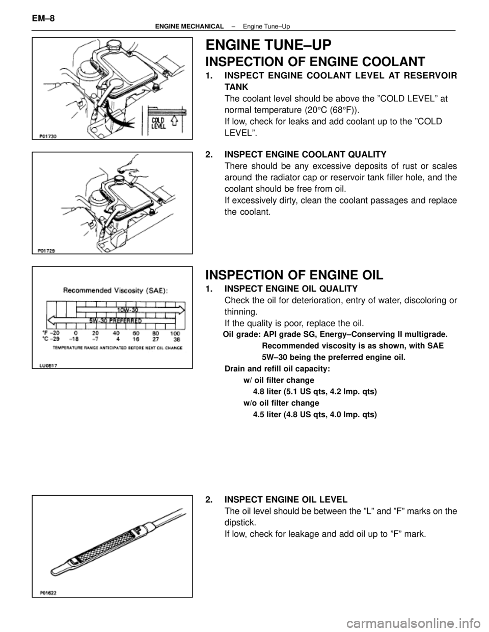
1. INSPECT ENGINE COOLANT LEVEL AT RESERVOIRTANK
The coolant level should be above the ºCOLD LEVELº at
normal temperature (20 5C (68 5F)).
If low, check for leaks and add coolant up to the ºCOLD
LEVELº.
2. INSPECT ENGINE COOLANT QUALITY There should be any excessive deposits of rust or scales
around the radiator cap or reservoir tank filler hole, and the
coolant should be free from oil.
If excessively dirty, clean the coolant passages and replace
the coolant.
INSPECTION OF ENGINE OIL
1. INSPECT ENGINE OIL QUALITYCheck the oil for deterioration, entry of water, discoloring or
thinning.
If the quality is poor, replace the oil.
Oil grade: API grade SG, Energy±Conserving II multigrade.
Recommended viscosity is as shown, with SAE
5W±30 being the preferred engine oil.
Drain and refill oil capacity: w/ oil filter change4.8 liter (5.1 US qts, 4.2 lmp. qts)
w/o oil filter change 4.5 liter (4.8 US qts, 4.0 lmp. qts)
2. INSPECT ENGINE OIL LEVEL The oil level should be between the ºLº and ºFº marks on the
dipstick.
If low, check for leakage and add oil up to ºFº mark.
EM±8
±
ENGINE MECHANICAL Engine Tune±Up
WhereEverybodyKnowsYourName
Page 1691 of 4087
REMOVAL OF TIMING BELT
(See Components on page EM±23)1. REMOVE WATER PUMP PULLEY AND RADIATOR (See steps 1 to 3, 6 and 7 on pages EM±64 and 66)
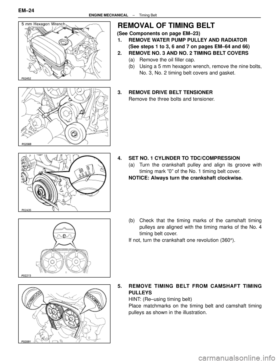
2. REMOVE NO. 3 AND NO. 2 TIMING BELT COVERS (a) Remove the oil filler cap.
(b) Using a 5 mm hexagon wrench, remove the nine bolts,No. 3, No. 2 timing belt covers and gasket.
3. REMOVE DRIVE BELT TENSIONER Remove the three bolts and tensioner.
4. SET NO. 1 CYLINDER TO TDC/COMPRESSION (a) Turn the crankshaft pulley and align its groove withtiming mark º0º of the No. 1 timing belt cover.
NOTICE: Always turn the crankshaft clockwise.
(b) Check that the timing marks of the camshaft timing pulleys are aligned with the timing marks of the No. 4
timing belt cover.
If not, turn the crankshaft one revolution (360 5).
5. REMOVE TIMING BELT FROM CAMSHAFT TIMING PULLEYS
HINT: (Re±using timing belt)
Place matchmarks on the timing belt and camshaft timing
pulleys as shown in the illustration.
EM±24
±
ENGINE MECHANICAL Timing Belt
WhereEverybodyKnowsYourName
Page 1700 of 4087
14. INSTALL NO. 2 AND NO. 3 TIMING BELT COVERS(a) Install the gasket on the timing belt cover.
(b) Using a 5 mm hexagon wrench, install the belt coverswith the nine bolts.
(c) Install the oil filler cap.
15. INSTALL RADIATOR AND WATER PUMP PULLEY (See steps 15, 16, 19 and 24 on pages EM±110 to 112)
16. FILL ENGINE WITH COOLANT (See page CO±5)
Capacity (w/ Heater):
M/T 8.5 liters (9.0 US qts, 7.5 Imp. qts)
A/T 8.4 liters (8.9 US qts, 7.4 Imp. qts)
17. (A/T)CHECK AUTOMATIC TRANSMISSION FLUID LEVEL
(See page MA±11)
NOTICE: Do not overfill.
18. START ENGINE AND CHECK FOR LEAKS
19. CHECK IGNITION TIMING (See page IG±14)
Ignition timing:
105 BTDC @ idle
(w/ Terminals TE1 and E1 connected)
20. PERFORM ROAD TEST Check for abnormal noise, shock, slippage, correct shift
points and smooth operation.
21. RECHECK ENGINE COOLANT LEVEL
±
ENGINE MECHANICAL Timing BeltEM±33
WhereEverybodyKnowsYourName
Page 1708 of 4087
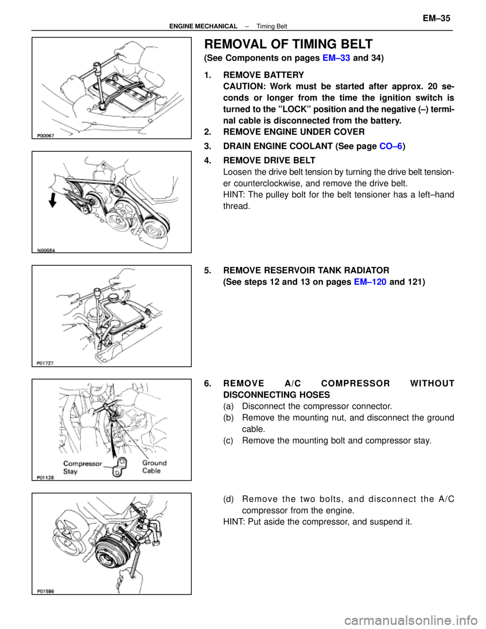
REMOVAL OF TIMING BELT
(See Components on pages EM±33 and 34)
1. REMOVE BATTERY CAUTION: Work must be started after approx. 20 se-
conds or longer from the time the ignition switch is
turned to the ºLOCKº position and the negative (±) termi-
nal cable is disconnected from the battery.
2. REMOVE ENGINE UNDER COVER
3. DRAIN ENGINE COOLANT (See page CO±6)
4. REMOVE DRIVE BELT Loosen the drive belt tension by turning the drive belt tension-
er counterclockwise, and remove the drive belt.
HINT: The pulley bolt for the belt tensioner has a left±hand
thread.
5. REMOVE RESERVOIR TANK RADIATOR (See steps 12 and 13 on pages EM±120 and 121)
6. REMOVE A/C COMPRESSOR WITHOUT DISCONNECTING HOSES
(a) Disconnect the compressor connector.
(b) Remove the mounting nut, and disconnect the groundcable.
(c) Remove the mounting bolt and compressor stay.
(d) R e m o v e t h e t w o b o l t s , a n d d i s c onnect the A/C
compressor from the engine.
HINT: Put aside the compressor, and suspend it.
±
ENGINE MECHANICAL Timing BeltEM±35
WhereEverybodyKnowsYourName
Page 1730 of 4087
37. INSTALL A/C COMPRESSOR(a) In sta ll th e A/C co mp re sso r, co mp re sso r sta y an dground cable with the three bolts and nut.
Torque: Bolt 49 N Vm (500 kgf Vcm, 36 ft Vlbf)
Nut 29 N Vm (300 kgf Vcm, 22 ft Vlbf)
(b) Connect the A/C compressor connector.
38. INSTALL RADIATOR AND RESERVOIR TANK (See steps 25 and 26 on pages EM±174 to 175)
39. INSTALL DRIVE BELT Install the drive belt by turning the drive belt tensioner coun-
terclockwise.
HINT: The pully bolt for the belt tensioner has a lefthand
thread.
40. INSTALL BATTERY
41. FILL WITH ENGINE COOLANT (See page CO±7)
42. CHECK IGNITION TIMING (See page IG±28)
Ignition timing:
8±125 BTDC @ idle
(w/ Terminals TE1 and E1 connected)
43. INSTALL ENGINE UNDER COVER
±
ENGINE MECHANICAL Timing BeltEM±57
WhereEverybodyKnowsYourName