1991 FORD FESTIVA tow
[x] Cancel search: towPage 157 of 454
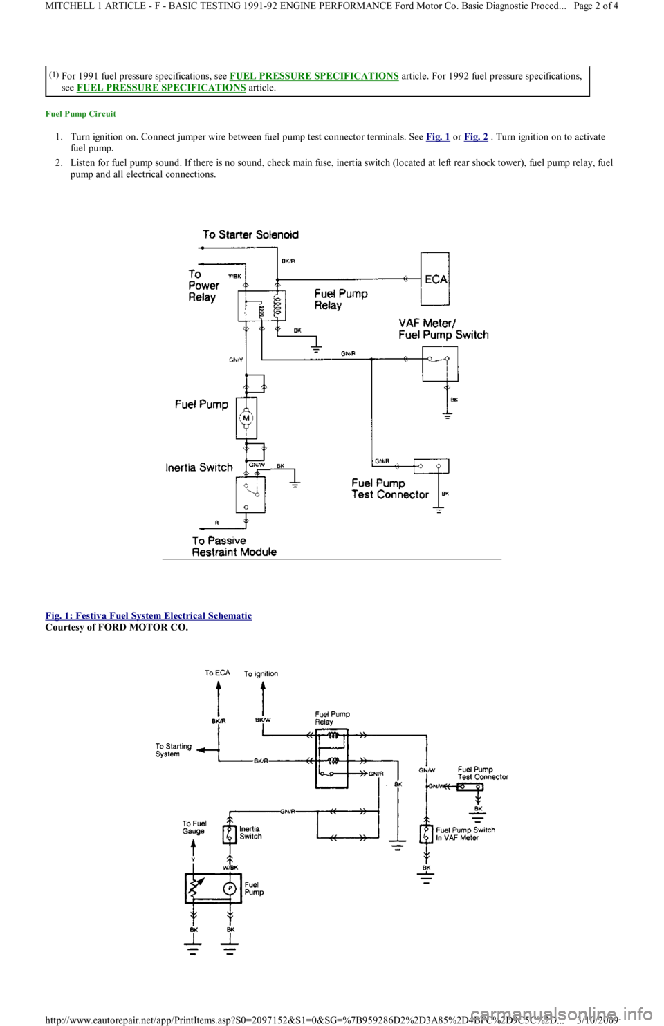
Fuel Pump Circuit
1. Turn ignition on. Connect jumper wire between fuel pump test connector terminals. See Fig. 1 or Fig. 2 . Turn ignition on to activate
fuel pump.
2. Listen for fuel pump sound. If there is no sound, check main fuse, inertia switch (located at left rear shock tower), fuel pump rel ay, fu el
pump and all electrical connections.
Fig. 1: Festiva Fuel System Electrical Schematic
Courtesy of FORD MOTOR CO.
(1)For 1991 fuel pressure specifications, see FUEL PRESSURE SPECIFICATIONS article. For 1992 fuel pressure specifications,
see FUEL PRESSURE SPECIFICATIONS
article.
Page 2 of 4 MITCHELL 1 ARTICLE - F - BASIC TESTING 1991-92 ENGINE PERFORMANCE Ford Motor Co. Basic Diagnostic Proced
...
3/10/2009 http://www.eautorepair.net/app/PrintItems.asp?S0=2097152&S1=0&SG=%7B959286D2%2D3A85%2D4BFC%2D9C5C%2D
...
Page 158 of 454
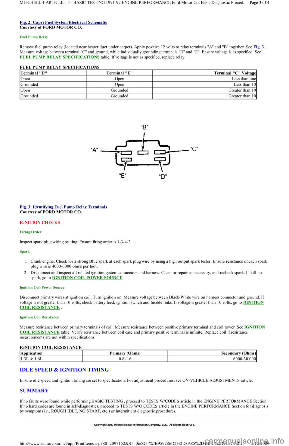
Fig. 2: Capri Fuel System Electrical Schematic
Courtesy of FORD MOTOR CO.
Fuel Pump Relay
Remove fuel pump relay (located near heater duct under carpet). Apply positive 12 volts to relay terminals "A" and "B" together. See Fig. 3 .
Measure voltage between terminal "C" and ground, while individually grounding terminals "D" and "E". Ensure voltage is as specified. See
FUEL PUMP RELAY SPECIFICATIONS
table. If voltage is not as specified, replace relay.
FUEL PUMP RELAY SPECIFICATIONS
Fig. 3: Identifying Fuel Pump Relay Terminals
Courtesy of FORD MOTOR CO.
IGNITION CHECKS
Firing Order
Inspect spark plug wiring routing. Ensure firing order is 1-3-4-2.
Spark
1. Crank engine. Check for a strong Blue spark at each spark plug wire by using a high output spark tester. Ensure resistance of each spark
plug wire is 4000-6000 ohms per foot.
2. Disconnect and inspect all related ignition system connectors and harness. Clean or repair as necessary, and recheck spark. If st il l n o
spark, go to IGNITION COIL POWER SOURCE
.
Ignition Coil Power Source
Disconnect primary wires at ignition coil. Turn ignition on. Measure voltage between Black/White wire on harness connector and ground. If
voltage is not greater than 10 volts, check battery feed, ignition switch and fusible links. If voltage is greater than 10 volts, go to IGNITION
COIL RESISTANCE .
Ignition Coil Resistance
Measure resistance between primary terminals of coil. Measure resistance between positive primary terminal and coil tower. See IGNITION
COIL RESISTANCE table. Verify resistance between coil case and primary positive terminal is infinite. Replace coil if resistance
measurements are not within specifications.
IGNITION COIL RESISTANCE
IDLE SPEED & IGNITION TIMING
Ensure idle speed and ignition timing are set to specification. For adjustment procedures, see ON-VEHICLE ADJUSTMENTS article.
SUMMARY
If no faults were found while performing BASIC TESTING , proceed to TESTS W/CODES article in the ENGINE PERFORMANCE Section.
If no hard codes are found in self-diagnostics, proceed to TESTS W/O CODES article in the ENGINE PERFORMANCE Section for diagnosis
by symptom (i.e., ROUGH IDLE, NO START, etc.) or intermittent diagnostic procedures.
Terminal "D"Terminal "E"Terminal "C" Voltage
OpenOpenLess than one
GroundedOpenLess than 10
OpenGroundedGreater than 10
GroundedGroundedGreater than 10
ApplicationPrimary (Ohms)Secondary (Ohms)
1.3L & 1.6L0.8-1.66000-30,000
Copyr ight 2009 Mitchell Repair Information Company, LLC. All Rights Reserved.
Page 3 of 4 MITCHELL 1 ARTICLE - F - BASIC TESTING 1991-92 ENGINE PERFORMANCE Ford Motor Co. Basic Diagnostic Proced
...
3/10/2009 http://www.eautorepair.net/app/PrintItems.asp?S0=2097152&S1=0&SG=%7B959286D2%2D3A85%2D4BFC%2D9C5C%2D
...
Page 172 of 454
WIGGLE TEST
Checking Circuitry
1. Visually inspect suspected sensor, switch, or solenoid. Enter WIGGLE TEST if using Super Star II tester. If using VOM, connect it to
STO terminal on self-test connector, and ground STI self-test connector terminal. Lightly tap sensor, switch, or solenoid.
2. Push and pull on suspected sensor, switch, or solenoid connector, but DO NOT unplug it. Test and wiggle harness vigorously, working
in small sections, from suspected device toward dash panel, and from dash panel to ECA.
3. If VOM or Super Star II tester does not display a positive indication of an intermittent defect, carefully disconnect suspected device.
Remove terminals from connector.
4. Inspect terminals at both ends for corrosion, bad crimps, or improperly seated terminals. Reconnect after inspection. Unplug harness
fro m E CA.
5. Inspect ECA and harness connector terminals for corrosion, bad crimps, or improperly seated terminals. If VOM does not indicate any
intermittent defect, reconnect wiring and erase codes.
PINPOINT TESTS
HOW TO USE PINPOINT TESTS
1. DO NOT perform any PINPOINT TEST unless directed by a QUICK TESTS procedure. Ensure all non-EEC related defects are
corrected. Follow each test step in order until defect is found. DO NOT replace any part unless so directed. When more than one service
code exists, start with first code displayed.
2. PINPOINT TESTS require ensuring electrical circuits are okay before replacing sensors or any other components. Always test circuits
for continuity between sensor and ECA. Test all circuits for shorts to power, opens, or shorts to ground. VREF and VPWR circuits
should be tested with KOEO or as specified in PINPOINT TESTS.
3. DO NOT measure voltage or resistance at ECA, or connect any test light unless specified in testing procedure. DO NOT pierce wiring.
Isolate both ends of a circuit and turn key off whenever checking for shorts or continuity, unless otherwise specified.
4. Disconnect solenoids and switches before checking circuit continuity or energizing solenoids.
5. An open is defined as any resistance greater than 10,000 ohms, unless otherwise specified.
6. To help diagnose circuits to ECA, turn ignition off and disconnect ECA harness. Connect BOB between ECA and ECA harness to
perform circuit and pinpoint tests.
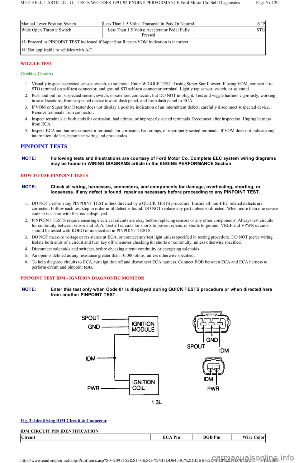
PINPOINT TEST IDM - IGNITION DIAGNOSTIC MONITOR
Fig. 3: Identifying IDM Circuit & Connector
IDM CIRCUIT PIN IDENTIFICATION
Manual Lever Position SwitchLess Than 1.5 Volts; Transaxle In Park Or NeutralSTP
Wide Open Throttle SwitchLess Than 1.5 Volts; Accelerator Pedal Fully
PressedSTG
(1)Proceed to PINPOINT TEST indicated if Super Star II tester/VOM indication is incorrect.
(2)Not applicable to vehicles with A/T.
NOTE:Following tests and illustrations are courtesy of Ford Motor Co. Com plete EEC system wiring diagram s
m ay be found in WIRING DIAGRAMS article in the ENGINE PERFORMANCE Section.
NOTE:Check all wiring, harnesses, connectors, and com ponents for dam age, overheating, shorting, or
looseness. If any defect is found, repair as necessary before proceeding to any PINPOINT T EST .
NOTE:Enter this test only when Code 01 is displayed during QUICK T EST S procedure or when directed here
from another PINPOINT TEST.
CircuitECA PinBOB PinWire Color
Page 5 of 20 MITCHELL 1 ARTICLE - G - TESTS W/CODES 1991-92 ENGINE PERFORMANCE Ford Motor Co. Self-Diagnostics
3/10/2009 http://www.eautorepair.net/app/PrintItems.asp?S0=2097152&S1=0&SG=%7B7DD6473C%2DB5BB%2D4F20%2D9D70%2D
...
Page 235 of 454
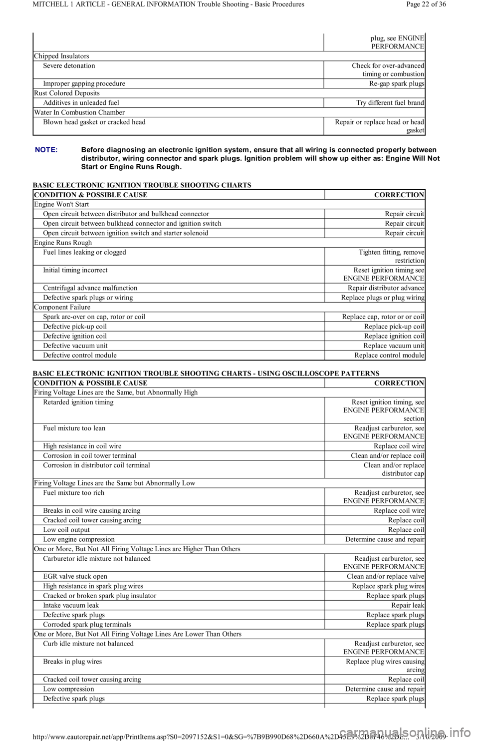
BASIC ELECTRONIC IGNITION TROUBLE SHOOTING CHARTS
BASIC ELECTRONIC IGNITION TROUBLE SHOOTING CHARTS - USING OSCILLOSCOPE PATTERNS
plug, see ENGINE
PERFORMANCE
Chipped Insulators
Severe detonationCheck for over-advanced
timing or combustion
Improper gapping procedureRe-gap spark plugs
Rust Colored Deposits
Additives in unleaded fuelTry different fuel brand
Water In Combustion Chamber
Blown head gasket or cracked headRepair or replace head or head
ga ske t
NOTE:Before diagnosing an electronic ignition system , ensure that all wiring is connected properly between
distributor, wiring connector and spark plugs. Ignition problem will show up either as: Engine Will Not
Start or Engine Runs Rough.
CONDITION & POSSIBLE CAUSECORRECTION
Engine Won't Start
Open circuit between distributor and bulkhead connectorRepair circuit
Open circuit between bulkhead connector and ignition switchRepair circuit
Open circuit between ignition switch and starter solenoidRepair circuit
Engine Runs Rough
Fuel lines leaking or cloggedTigh t e n fit t in g, r e mo ve
restriction
Initial timing incorrectReset ignition timing see
ENGINE PERFORMANCE
Centrifugal advance malfunctionRepair distributor advance
Defective spark plugs or wiringReplace plugs or plug wiring
Component Failure
Spark arc-over on cap, rotor or coilReplace cap, rotor or or coil
Defective pick-up coilReplace pick-up coil
Defective ignition coilReplace ignition coil
Defective vacuum unitReplace vacuum unit
Defective control moduleReplace control module
CONDITION & POSSIBLE CAUSECORRECTION
Firing Voltage Lines are the Same, but Abnormally High
Retarded ignition timingReset ignition timing, see
ENGINE PERFORMANCE
section
Fuel mixture too leanReadjust carburetor, see
ENGINE PERFORMANCE
High resistance in coil wireReplace coil wire
Corrosion in coil tower terminalClean and/or replace coil
Corrosion in distributor coil terminalClean and/or replace
distributor cap
Firing Voltage Lines are the Same but Abnormally Low
Fuel mixture too richReadjust carburetor, see
ENGINE PERFORMANCE
Breaks in coil wire causing arcingReplace coil wire
Cracked coil tower causing arcingReplace coil
Low coil outputReplace coil
Low engine compressionDetermine cause and repair
One or More, But Not All Firing Voltage Lines are Higher Than Others
Carburetor idle mixture not balancedReadjust carburetor, see
ENGINE PERFORMANCE
EGR valve stuck openClean and/or replace valve
High resistance in spark plug wiresReplace spark plug wires
Cracked or broken spark plug insulatorReplace spark plugs
Intake vacuum leakRepair leak
Defective spark plugsReplace spark plugs
Corroded spark plug terminalsReplace spark plugs
One or More, But Not All Firing Voltage Lines Are Lower Than Others
Curb idle mixture not balancedReadjust carburetor, see
ENGINE PERFORMANCE
Breaks in plug wiresReplace plug wires causing
arcing
Cracked coil tower causing arcingReplace coil
Low compressionDetermine cause and repair
Defective spark plugsReplace spark plugs
Page 22 of 36 MITCHELL 1 ARTICLE - GENERAL INFORMATION Trouble Shooting - Basic Procedures
3/10/2009 http://www.eautorepair.net/app/PrintItems.asp?S0=2097152&S1=0&SG=%7B9B990D68%2D660A%2D45E9%2D8F46%2DE
...
Page 255 of 454
Back To Article
GENERAL INFORMATION
Gear T ooth Contact Patterns
* PLEASE READ THIS FIRST *
INSPECTION
Wipe lubricant from internal parts. Rotate gears and inspect for wear or damage. Mount dial indicator to housing and check backlash at several
points around ring gear. Backlash must be within specification at all points. If no defects are found, check gear tooth pattern contact.
GEAR TOOTH CONTACT PATTERN
1. Paint ring gear teeth with marking compound. Wrap cloth or rope around drive pinion flange to act as brake. Rotate gear until clear
contact pattern is obtained.
2. Contact pattern will indicate whether correct pinion bearing mounting shim has been installed and if drive gear backlash has been set
properly. Backlash between drive gear pinion must be maintained within specified limits until correct tooth pattern is obtained.
ADJUSTMENTS
GEAR BACKLASH & PINION SHIM CHANGES
1. With no change in backlash, moving pinion further from ring gear moves drive pattern toward heel and top of tooth, and moves coast
pattern toward toe and top of tooth.
2. With no change in backlash, moving pinion closer to ring gear moves drive pattern toward toe and bottom of tooth, and moves coast
pattern toward heel and bottom of tooth.
3. With no change in pinion shim thickness, an increase in backlash moves ring gear further from pinion. Both drive and coast patterns
move toward heel and top of tooth.
4. With no change in pinion shim thickness, a decrease in backlash moves ring gear closer to pinion gear. Both drive and coast patterns
move toward toe and bottom of tooth. NOTE:This is GENERAL inform ation. This article is not intended to be specific to any unique situation or
individual vehicle configuration. For m odel-specific inform ation see appropriate articles where
available.
NOTE:This is GENERAL inform ation. This article is not intended to be specific to any unique situation or
individual vehicle configuration. For m odel-specific inform ation see appropriate articles where
available.
NOTE:Drive pattern should be well centered on ring gear teeth. Coast pattern should be centered, but m ay be
slightly toward toe of ring gear teeth.
NOTE:This is GENERAL inform ation. This article is not intended to be specific to any unique situation or
individual vehicle configuration. For m odel-specific inform ation see appropriate articles where
available.
NOTE:This is GENERAL inform ation. This article is not intended to be specific to any unique situation or
individual vehicle configuration. For m odel-specific inform ation see appropriate articles where
available.
NOTE:This is GENERAL inform ation. This article is not intended to be specific to any unique situation or
individual vehicle configuration. For m odel-specific inform ation see appropriate articles where
available.
Page 1 of 2 MITCHELL 1 ARTICLE - GENERAL INFORMATION Gear Tooth Contact Patterns
3/10/2009 http://www.eautorepair.net/app/PrintItems.asp?S0=2097152&S1=0&SG=%7B9B990D68%2D660A%2D45E9%2D8F46%2DE
...
Page 274 of 454
Back To Article
GENERAL INFORMATION
Engine Perform ance Safety Precautions
Always refer to Emission Decal in engine compartment before servicing vehicle. If manual and decal differ, always use decal
specifications.
Do not allow or create a condition of misfire in more than one cylinder for an extended period of time. Damage to converter may occur
due to loading converter with unburned air/fuel mixture.
Always turn ignition off and disconnect negative battery cable BEFORE disconnecting or connecting computer or other electrical
components.
DO NOT drop or shock electrical components such as computer, airflow meter, etc.
DO NOT use fuel system cleaning compounds that are not recommended by the manufacturer. Damage to gaskets, diaphragm materials
and catalytic converter may result.
Before performing a compression test or cranking engine using a remote starter switch, disconnect coil wire from distributor and secure it
to a good engine ground, or disable ignition.
Before disconnecting any fuel system component, ensure fuel system pressure is released.
Use a shop towel to absorb any spilled fuel to prevent fire.
DO NOT create sparks or have an open flame near battery.
If any fuel system components such as hoses or clamps are replaced, ensure they are replaced with components designed for fuel system
use.
Always reassemble throttle body components with new gaskets, "O" rings and seals.
If equipped with an inertia switch, DO NOT reset switch until fuel system has been inspected for leaks.
We a r sa fe t y go ggl e s wh e n d r il l in g o r gr in d in g.
Wear proper clothing which protects against chemicals and other hazards.
Copyr ight 2009 Mitchell Repair Information Company, LLC. All Rights Reserved.
Article GUID: A00002342
Page 1 of 1 MITCHELL 1 ARTICLE - GENERAL INFORMATION Engine Performance Safety Precautions
3/10/2009 http://www.eautorepair.net/app/PrintItems.asp?S0=2097152&S1=0&SG=%7B9B990D68%2D660A%2D45E9%2D8F46%2DE
...
Page 286 of 454
The voltage controlled driver inside the computer operates much like a simple switch because it does not need to worry about limiting current
flow. Recall, this driver typically requires injector circuits with a total leg resistance of 12 or more ohms.
The driver is either ON, closing/completing the circuit (eliminating the voltage-drop), or OFF, opening the circuit (causing a total voltage
drop).
Some manufacturers call it a "saturated switch" driver. This is because when switched ON, the driver allows the magnetic field in the injector
to build to saturation. This is the same "saturation" property that you are familiar with for an ignition coil.
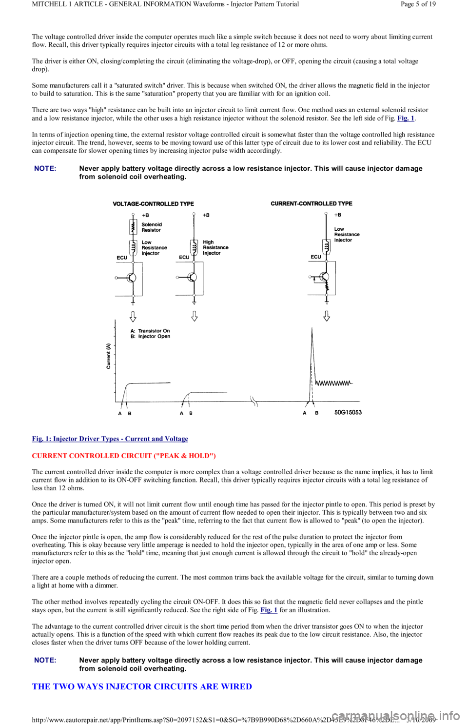
There are two ways "high" resistance can be built into an injector circuit to limit current flow. One method uses an external solenoid resistor
and a low resistance injector, while the other uses a high resistance injector without the solenoid resistor. See the left side of Fig. Fig. 1
.
In terms of injection opening time, the external resistor voltage controlled circuit is somewhat faster than the voltage controlled high resistance
injector circuit. The trend, however, seems to be moving toward use of this latter type of circuit due to its lower cost and reliability. The ECU
can compensate for slower opening times by increasing injector pulse width accordingly.
Fig. 1: Injector Driver Types
- Current and Voltage
CURRENT CONTROLLED CIRCUIT ("PEAK & HOLD")
The current controlled driver inside the computer is more complex than a voltage controlled driver because as the name implies, it has to limit
current flow in addition to its ON-OFF switching function. Recall, this driver typically requires injector circuits with a total leg resistance of
less than 12 ohms.
Once the driver is turned ON, it will not limit current flow until enough time has passed for the injector pintle to open. This period is preset by
the particular manufacturer/system based on the amount of current flow needed to open their injector. This is typically between two and six
amps. Some manufacturers refer to this as the "peak" time, referring to the fact that current flow is allowed to "peak" (to open the injector).
Once the injector pintle is open, the amp flow is considerably reduced for the rest of the pulse duration to protect the injector from
overheating. This is okay because very little amperage is needed to hold the injector open, typically in the area of one amp or less. Some
manufacturers refer to this as the "hold" time, meaning that just enough current is allowed through the circuit to "hold" the already-open
injector open.
There are a couple methods of reducing the current. The most common trims back the available voltage for the circuit, similar to turning down
a light at home with a dimmer.
The other method involves repeatedly cycling the circuit ON-OFF. It does this so fast that the magnetic field never collapses and the pintle
stays open, but the current is still significantly reduced. See the right side of Fig. Fig. 1
for an illustration.
The advantage to the current controlled driver circuit is the short time period from when the driver transistor goes ON to when the injector
actually opens. This is a function of the speed with which current flow reaches its peak due to the low circuit resistance. Also, the injector
closes faster when the driver turns OFF because of the lower holding current.
THE TWO WAYS INJECTOR CIRCUITS ARE WIRED
NOTE:Never apply battery voltage directly across a low resistance injector. T his will cause injector dam age
from solenoid coil overheating.
NOTE:Never apply battery voltage directly across a low resistance injector. T his will cause injector dam age
from solenoid coil overheating.
Page 5 of 19 MITCHELL 1 ARTICLE - GENERAL INFORMATION Waveforms - Injector Pattern Tutorial
3/10/2009 http://www.eautorepair.net/app/PrintItems.asp?S0=2097152&S1=0&SG=%7B9B990D68%2D660A%2D45E9%2D8F46%2DE
...
Page 306 of 454
Back To Article
1991 GENERAL SERVICING
A/C Com pressor Refrigerant Oil Checking
ISOLATING COMPRESSOR
1. Connect service gauge set to the compressor service valves and open compressor valves slightly (turn in clockwise). Start engine and
operate air conditioning. Slowly turn compressor suction valve clockwise toward closed (front-seated) position.
2. When suction pressure is reduced to zero or less, turn off engine and compressor and quickly turn suction valve stem in to full front-
seated position. Suction pressure should be slightly above zero. Turn discharge valve into front-seated position.
3. To check oil level, slowly open compressor crankcase plug to relieve any remaining pressure. After oil level is corrected, cap service
gauge ports on both valves. Back-seat suction service valve to allow refrigerant to enter compressor. Open discharge valve halfway.
4. Loosen discharge service valve cap, allowing refrigerant pressure to force air out of compressor. Back-seat service valve and tighten cap.
Compressor is now ready for operation.
REFRIGERANT OIL
Only new, pure, moisture-free refrigerant oil should be used in the air conditioning system. This oil is highly refined and dehydrated to a point
where moisture content is less than 10 parts per million. The oil container must be tightly closed at all times when not in use, or moisture will
be absorbed into the refrigerant oil from the air.
SERVICING PRECAUTIONS
DISCHARGING SYSTEM PRECAUTIONS
If compressor has stem-type service valves, it can be isolated and removed without discharging entire system. See ISOLATING
COMPRESSOR at the beginning of this article. Otherwise, discharge system completely before loosening any fittings.
DISCONNECTING LINES & FITTINGS TEST
After system is discharged, carefully clean area around all fittings to be opened. Always use 2 wrenches when tightening or loosening fittings
to avoid twisting or distorting lines. Cap or plug all openings as soon as lines are removed. DO NOT remove caps until immediately before
connections are made. This will keep entry of air and moisture to a minimum.
CONNECTING LINES AND FITTINGS
A new gasket or "O" ring should be used in all instances when connecting lines or fittings. Dip "O" ring in new refrigerant oil and ensure it is
not twisted during installation. Always use 2 wrenches to prevent damage to lines and fittings.
PLACING SYSTEM IN OPERATION
After component service or replacement has been completed and all connections have been made, evacuate system thoroughly with a vacuum
pump. Charge system with proper amount of refrigerant and perform a leak test. See REFRIGERANT OIL & R-12 SPECIFICATIONS chart in
this section for system capacities. Be sure to check all fittings that have been opened. After system has been leak tested, make a system
performance check.
ATSUGI ROTARY VANE DRAIN & REFILL
1. Before checking and adjusting oil level, operate compressor at engine idling speed, with controls set for maximum cooling and high
blower speed, for 20 to 30 minutes to return oil to compressor.
2. Stop engine, discharge refrigerant and remove compressor from vehicle. See SERVICING PRECAUTIONS at beginning of article. Drain
compressor oil from compressor discharge port and measure the amount. Oil is sometimes hard to drain when compressor is cool.
Remove oil while compressor is warm.
3. If the amount drained is less than 3 ounces, conduct leak tests at system connections, and if necessary, repair or replace faulty parts.
Check purity of oil and adjust oil level as follows.
4. If amount drained was above 3 ounces, oil level is right. Pour in same amount as was drained. If amount drained was below 3 ounces,
pour in 3 ounces of new refrigerant oil.
BOSCH 6-CYL DRAIN & REFILL
1. Before checking and adjusting oil level, operate compressor at engine idling speed, with controls set for maximum cooling and high
blower speed, for 20 to 30 minutes to return oil to compressor.
2. Stop engine and discharge refrigerant. Remove refrigerant oil level inspection plug on side of compressor. Oil should be at lower lip of
threaded hole. Add necessary new refrigerant oil (if low). Replace inspection plug and tighten to 10-12 ft. lbs. (14-16 N.m). NOTE:Only com pressors with stem -type service valves can be isolated.
NOTE:Recent findings by the EPA indicate that refrigerant is harm ful to the earth's protective Ozone layer.
When discharging refrigerant, DO NOT allow refrigerant to enter the atm osphere. If available, use
refrigerant recovery/recycle system s when discharging system . Always follow m anufacturer's
instructions.
NOTE:Air conditioning system s will not norm ally need addition of refrigerant oil unless definite oil loss has
occurred due to ruptured lines, leaking com pressor seals, com pressor overhaul or com ponent
replacem ent.
Page 1 of 4 MITCHELL 1 ARTICLE - 1991 GENERAL SERVICING A/C Compressor Refrigerant Oil Checking
3/10/2009 http://www.eautorepair.net/app/PrintItems.asp?S0=2097152&S1=0&SG=%7B9B990D68%2D660A%2D45E9%2D8F46%2DE
...