Page 1481 of 1640
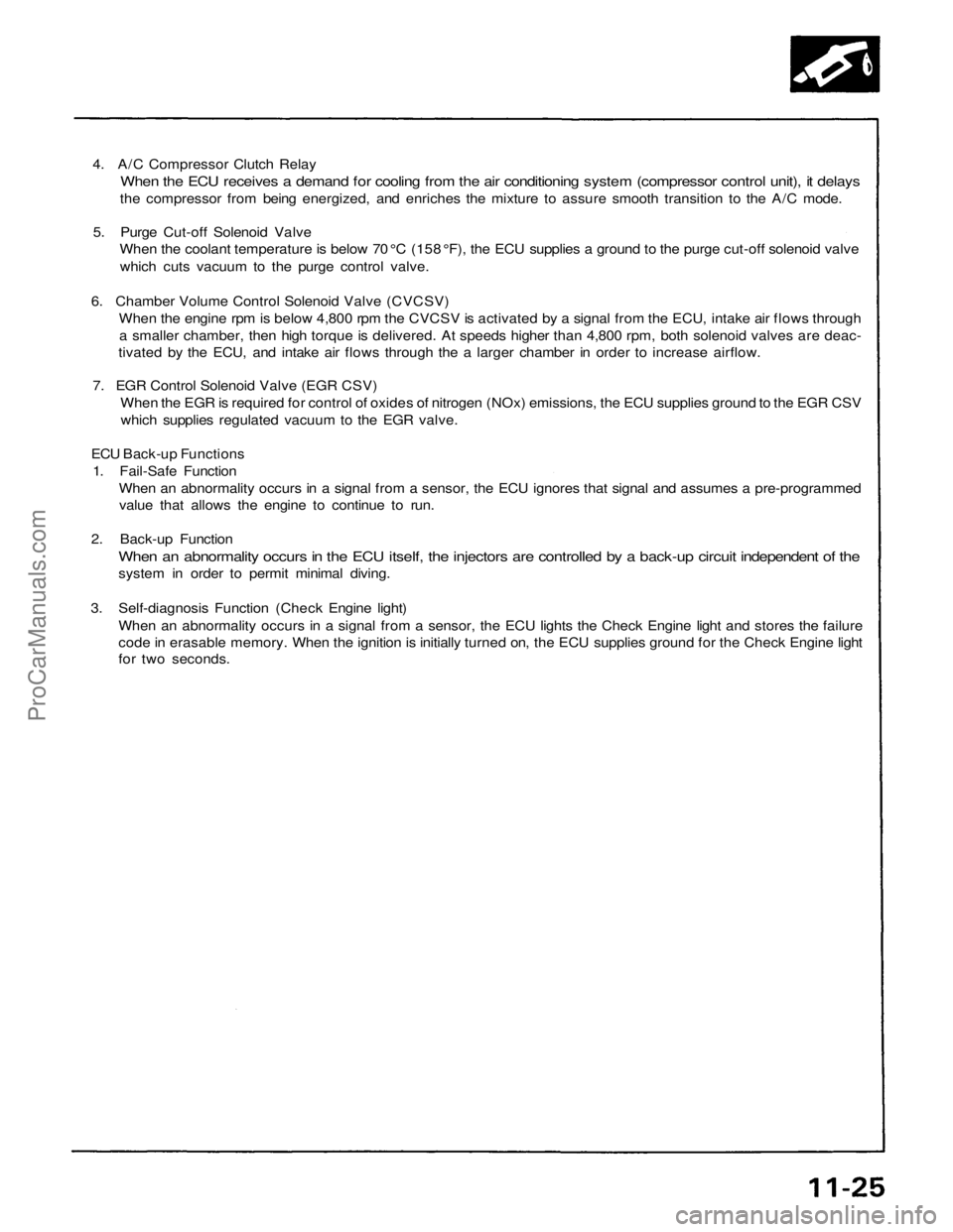
4. A/C Compressor Clutch Relay
When the ECU receives a demand for cooling from the air conditioning system (compressor control unit), it delays
the compressor from being energized, and enriches the mixture to assure smooth transition to the A/C mode.
5. Purge Cut-off Solenoid Valve
When the coolant temperature is below 70 °C (158 °F), the ECU supplies a ground to the purge cut-off solenoid valve
which cuts vacuum to the purge control valve.
6. Chamber Volume Control Solenoid Valve (CVCSV)
When the engine rpm is below 4,800 rpm the CVCSV is activated by a signal from the ECU, intake air flows through
a smaller chamber, then high torque is delivered. At speeds higher than 4,800 rpm, both solenoid valves are deac-
tivated by the ECU, and intake air flows through the a larger chamber in order to increase airflow.
7. EGR Control Solenoid Valve (EGR CSV)
When the EGR is required for control of oxides of nitrogen (NOx) emissions, the ECU supplies ground to the EGR CSV
which supplies regulated vacuum to the EGR valve.
ECU Back-up Functions
1. Fail-Safe Function
When an abnormality occurs in a signal from a sensor, the ECU ignores that signal and assumes a pre-programmed
value that allows the engine to continue to run.
2. Back-up Function
When an abnormality occurs in the ECU itself, the injectors are controlled by a back-up circuit independent of the
system in order to permit minimal diving.
3. Self-diagnosis Function (Check Engine light)
When an abnormality occurs in a signal from a sensor, the ECU lights the Check Engine light and stores the failure
code in erasable memory. When the ignition is initially turned on, the ECU supplies ground for the Check Engine light
for two seconds.ProCarManuals.com
Page 1487 of 1640
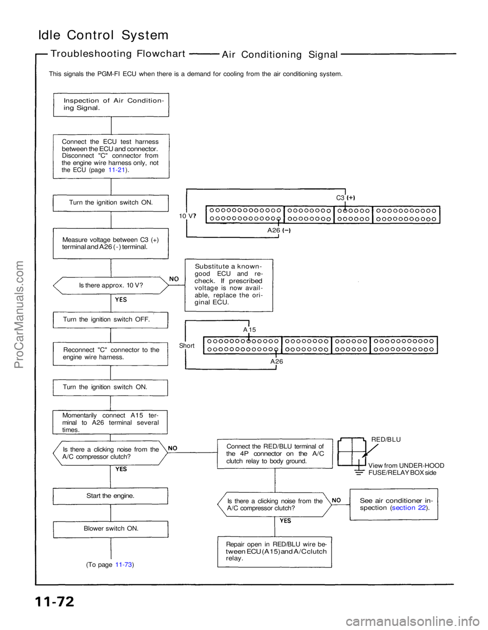
Idle Control System
Troubleshooting Flowchart
Air Conditioning Signal
This signals the PGM-FI ECU when there is a demand for cooling from the air conditioning system.
Inspection of Air Condition-
ing Signal.
Connect the ECU test harness
between the ECU and connector.
Disconnect "C" connector from
the engine wire harness only, not
the ECU (page 11-21).
Turn the ignition switch ON.
Measure voltage between C3 (+)
terminal and A26 (-) terminal.
Is there approx. 10 V?
Substitute a known-
good ECU and re-
check. If prescribed
voltage is now avail- able, replace the ori-
ginal ECU.
C3
A26
10 V
Turn the ignition switch OFF. Reconnect "C" connector to the
engine wire harness.
Turn the ignition switch ON.
Momentarily connect A15 ter-
minal to A26 terminal several
times.
Is there a clicking noise from the
A/C compressor clutch? Connect the RED/BLU terminal of
the 4P connector on the A/C
clutch relay to body ground. RED/BLU
A 15
Short
A26
View from UNDER-HOODFUSE/RELAY BOX side
Start the engine.
Is there a clicking noise from the
A/C compressor clutch?
See air conditioner in-
spection (section 22).
Repair open in RED/BLU wire be-
tween ECU (A15) and A/C clutch
relay.
Blower switch ON.
(To page 11-73)ProCarManuals.com
Page 1489 of 1640
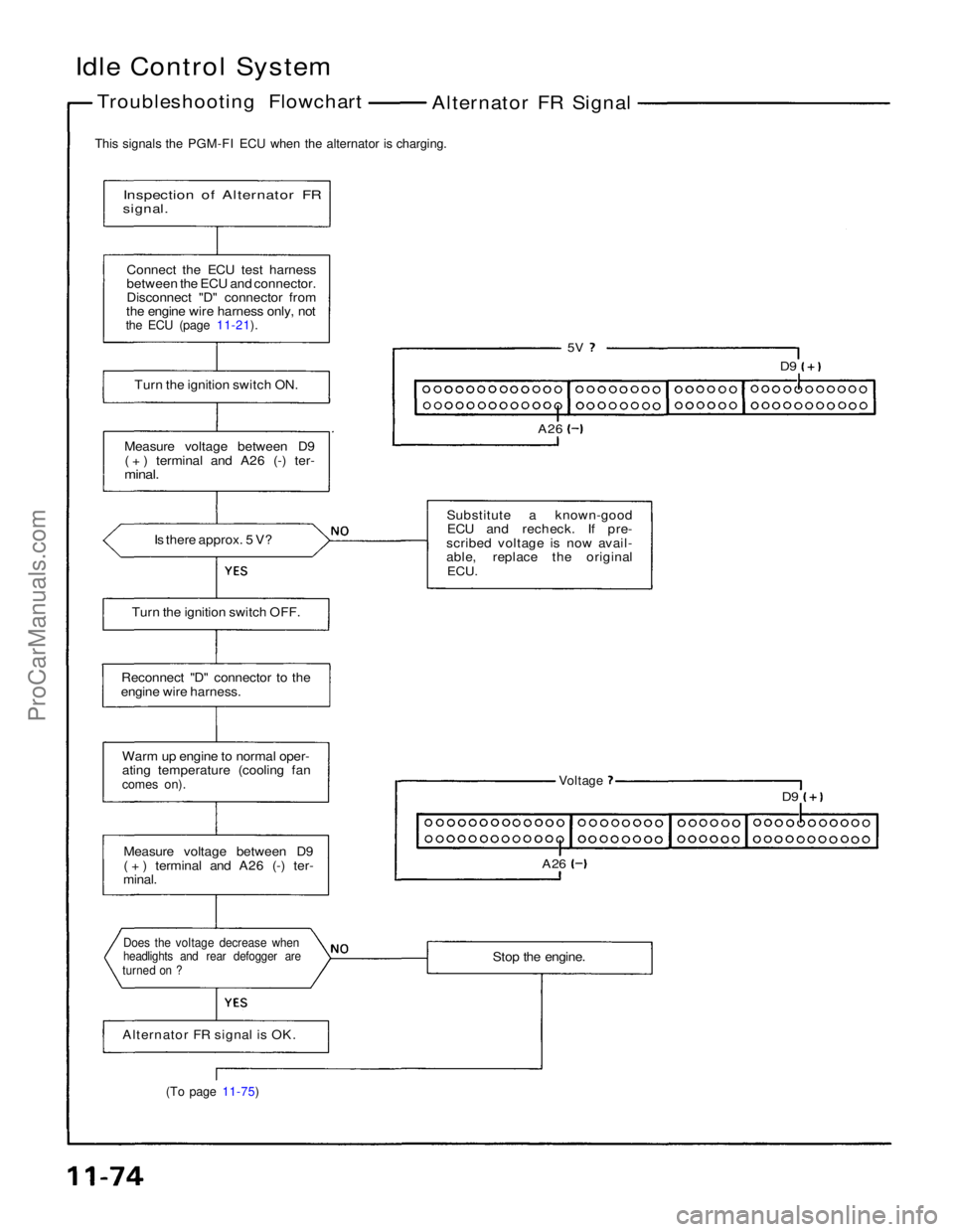
Idle Control System
Troubleshooting Flowchart Alternator FR Signal
This signals the PGM-FI ECU when the alternator is charging.
Inspection of Alternator FR
signal.
Connect the ECU test harness
between the ECU and connector.
Disconnect "D" connector from
the engine wire harness only, not
the ECU (page 11-21).
Turn the ignition switch ON.
Measure voltage between D9 ( + ) terminal and A26 (-) ter-
minal.
Is there approx. 5 V?
5V
D9
A26
Substitute a known-good ECU and recheck. If pre-
scribed voltage is now avail-
able, replace the original ECU.
Turn the ignition switch OFF.
Reconnect "D" connector to the
engine wire harness.
Warm up engine to normal oper-
ating temperature (cooling fan
comes on).
Voltage
D9
A26
Measure voltage between D9
( + ) terminal and A26 (-) ter-
minal.
Stop the engine.
Does the voltage decrease when
headlights and rear defogger are
turned on ?
Alternator FR signal is OK.
(To page 11-75)ProCarManuals.com
Page 1497 of 1640
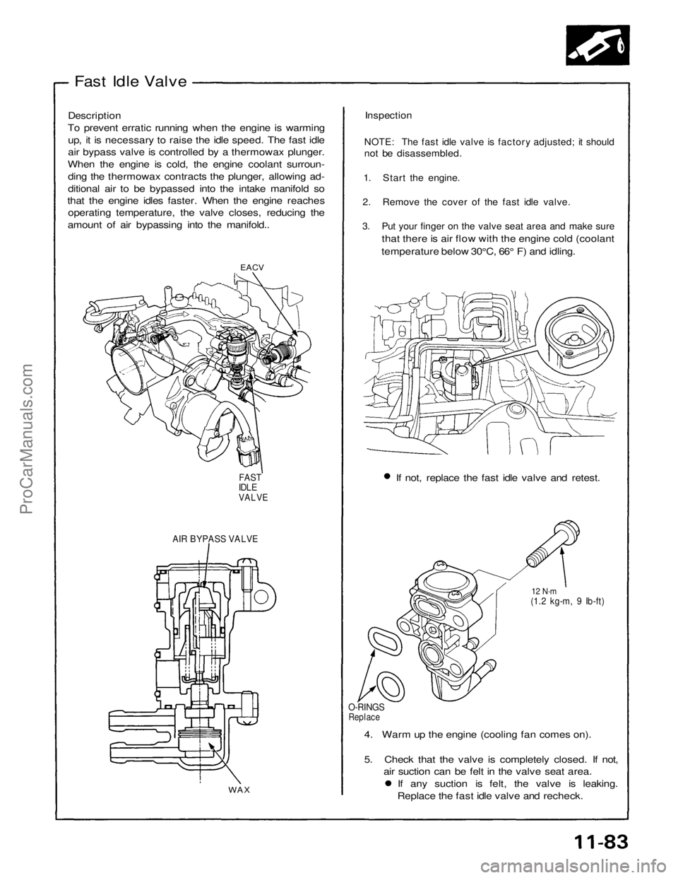
Fast Idle Valve
Description
To prevent erratic running when the engine is warming up, it is necessary to raise the idle speed. The fast idle
air bypass valve is controlled by a thermowax plunger.
When the engine is cold, the engine coolant surroun- ding the thermowax contracts the plunger, allowing ad-
ditional air to be bypassed into the intake manifold so
that the engine idles faster. When the engine reaches operating temperature, the valve closes, reducing the
amount of air bypassing into the manifold..
Inspection
NOTE: The fast idle valve is factory adjusted; it should
not be disassembled.
1. Start the engine.
2. Remove the cover of the fast idle valve.
3. Put your finger on the valve seat area and make sure
that there is air flow with the engine cold (coolant
temperature below 30°C, 66° F) and idling.
EACV
If not, replace the fast idle valve and retest.
FAST
IDLE
VALVE
AIR BYPASS VALVE
12 N·m
(1.2 kg-m, 9 Ib-ft)
O-RINGS
Replace
4. Warm up the engine (cooling fan comes on).
5. Check that the valve is completely closed. If not, air suction can be felt in the valve seat area. If any suction is felt, the valve is leaking.
Replace the fast idle valve and recheck.
WAXProCarManuals.com
Page 1498 of 1640
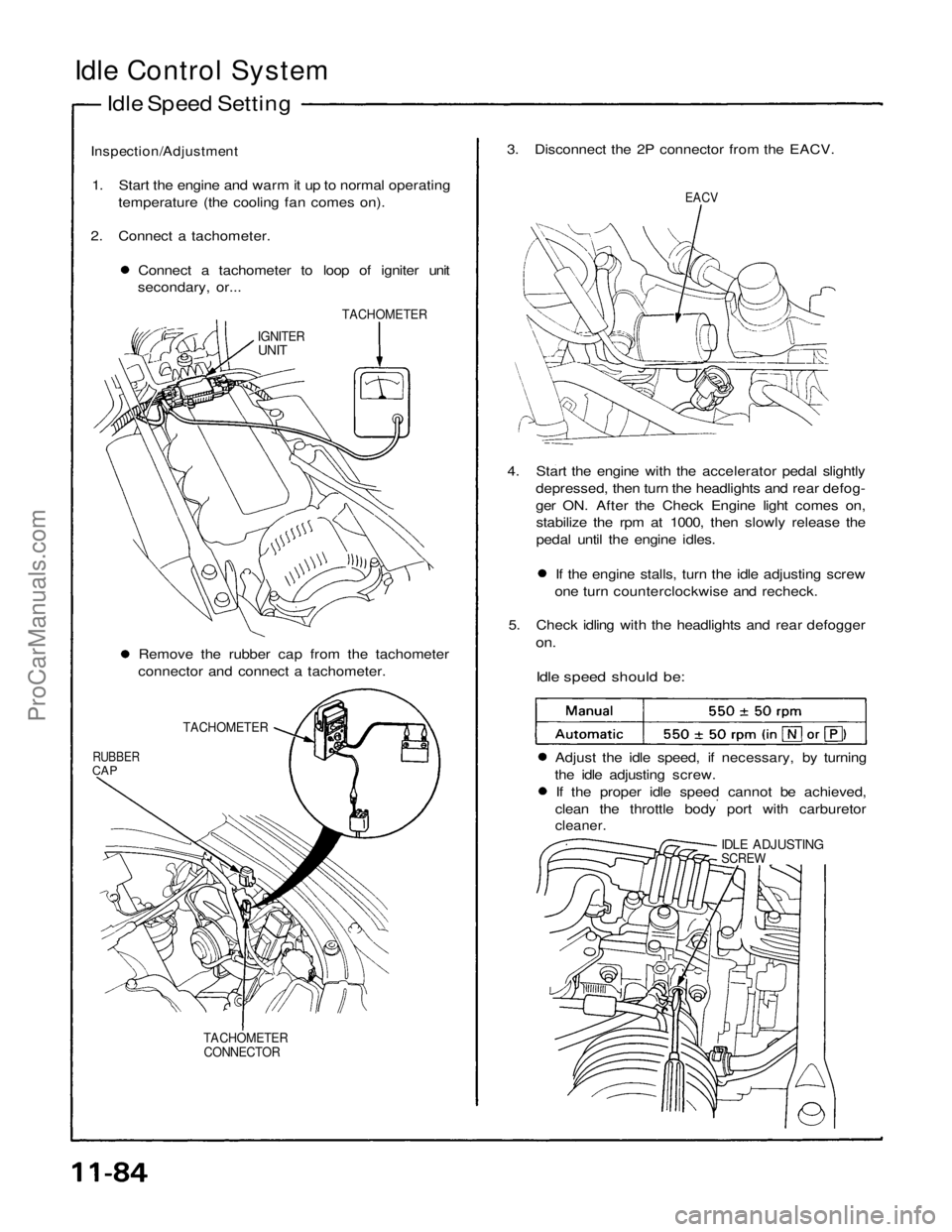
Idle Control System
Idle Speed Setting
Inspection/Adjustment
1. Start the engine and warm it up to normal operating temperature (the cooling fan comes on).
2. Connect a tachometer. Connect a tachometer to loop of igniter unit
secondary, or... 3. Disconnect the 2P connector from the EACV.
EACV
TACHOMETER
IGNITER
UNIT
4. Start the engine with the accelerator pedal slightlydepressed, then turn the headlights and rear defog-
ger ON. After the Check Engine light comes on,stabilize the rpm at 1000, then slowly release the
pedal until the engine idles. If the engine stalls, turn the idle adjusting screw
one turn counterclockwise and recheck.
5. Check idling with the headlights and rear defogger
on.
Idle speed should be:
Remove the rubber cap from the tachometer
connector and connect a tachometer.
TACHOMETER
RUBBER
CAP
Adjust the idle speed, if necessary, by turning
the idle adjusting screw. If the proper idle speed cannot be achieved,
clean the throttle body port with carburetor
cleaner.
IDLE ADJUSTING
SCREW
TACHOMETER CONNECTORProCarManuals.com
Page 1499 of 1640
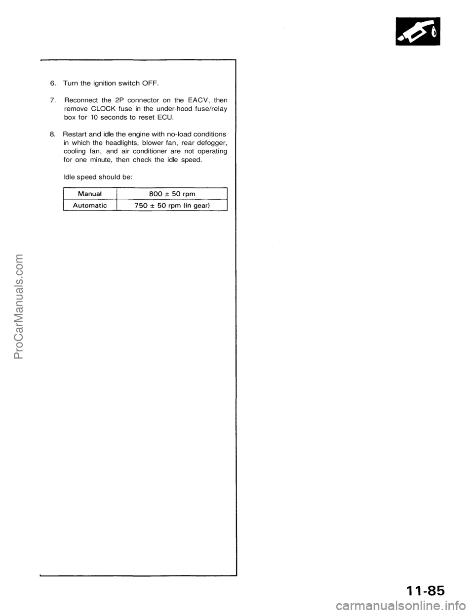
6. Turn the ignition switch OFF.
7. Reconnect the 2P connector on the EACV, then
remove CLOCK fuse in the under-hood fuse/relay
box for 10 seconds to reset ECU.
8. Restart and idle the engine with no-load conditions
in which the headlights, blower fan, rear defogger,
cooling fan, and air conditioner are not operating
for one minute, then check the idle speed.
Idle speed should be:ProCarManuals.com
Page 1519 of 1640
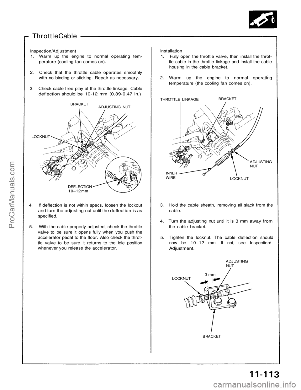
Throttle Cable
Inspection/Adjustment
1. Warm up the engine to normal operating tem-
perature (cooling fan comes on).
2. Check that the throttle cable operates smoothly with no binding or sticking. Repair as necessary.
3. Check cable free play at the throttle linkage. Cable
deflection should be 10-12 mm (0.39-0.47 in.)
Installation
1. Fully open the throttle valve, then install the throt- tle cable in the throttle linkage and install the cablehousing in the cable bracket.
2. Warm up the engine to normal operating temperature (the cooling fan comes on).
THROTTLE LINKAGE
BRACKET
ADJUSTING
NUT
LOCKNUT
INNER
WIRE
ADJUSTING NUT
BRACKET
LOCKNUT
DEFLECTION
10–12
mm
4. If deflection is not within specs, loosen the lockout
and turn the adjusting nut until the deflection is as
specified.
5. With the cable properly adjusted, check the throttle valve to be sure it opens fully when you push the
accelerator pedal to the floor. Also check the throt-
tle valve to be sure it returns to the idle position whenever you release the accelerator. 3. Hold the cable sheath, removing all slack from the
cable.
4. Turn the adjusting nut until it is 3 mm away from
the cable bracket.
5. Tighten the locknut. The cable deflection should now be 10–12 mm. If not, see Inspection/
Adjustment.
ADJUSTING
NUT
LOCKNUT
3 mm
BRACKETProCarManuals.com
Page 1520 of 1640
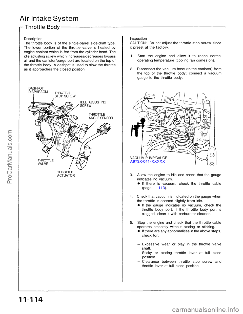
Air Intake System
Throttle Body
Description
The throttle body is of the single-barrel side-draft type.
The lower portion of the throttle valve is heated by
engine coolant which is fed from the cylinder head. Theidle adjusting screw which increases/decreases bypass
air and the canister/purge port are located on the top of
the throttle body. A dashpot is used to slow the throttle as it approaches the closed position.
Inspection
CAUTION: Do not adjust the throttle stop screw since
it preset at the factory.
1. Start the engine and allow it to reach normal operating temperature (cooling fan comes on).
2. Disconnect the vacuum hose (to the canister) from the top of the throttle body; connect a vacuum
gauge to the throttle body.
DASHPOT
DIAPHRAGM
THROTTLE
STOP SCREW
IDLE ADJUSTING
SCREW
THROTTLE
ANGLE SENSOR
VACUUM PUMP/GAUGE
A973X-041 -XXXXX
THROTTLE
VALVE
THROTTLE
ACTUATOR
3. Allow the engine to idle and check that the gauge
indicates no vacuum. If there is vacuum, check the throttle cable
(page 11-113).
4. Check that vacuum is indicated on the gauge when
the throttle is opened slightly from idle.
If the gauge indicates no vacuum, check the
throttle body port. If the throttle body port is clogged, clean it with carburetor cleaner.
5. Stop the engine and check that the throttle cable operates smoothly without binding or sticking. If there are any abnormalities in the above steps,
check for:
Excessive wear or play in the throttle valve
shaft.
Sticky or binding throttle lever at full close
position.
Clearance between throttle stop screw and
throttle lever at full close position.ProCarManuals.com