1991 ACURA NSX cooling
[x] Cancel search: coolingPage 998 of 1640
Engine Removal/Installation
(cont'd)
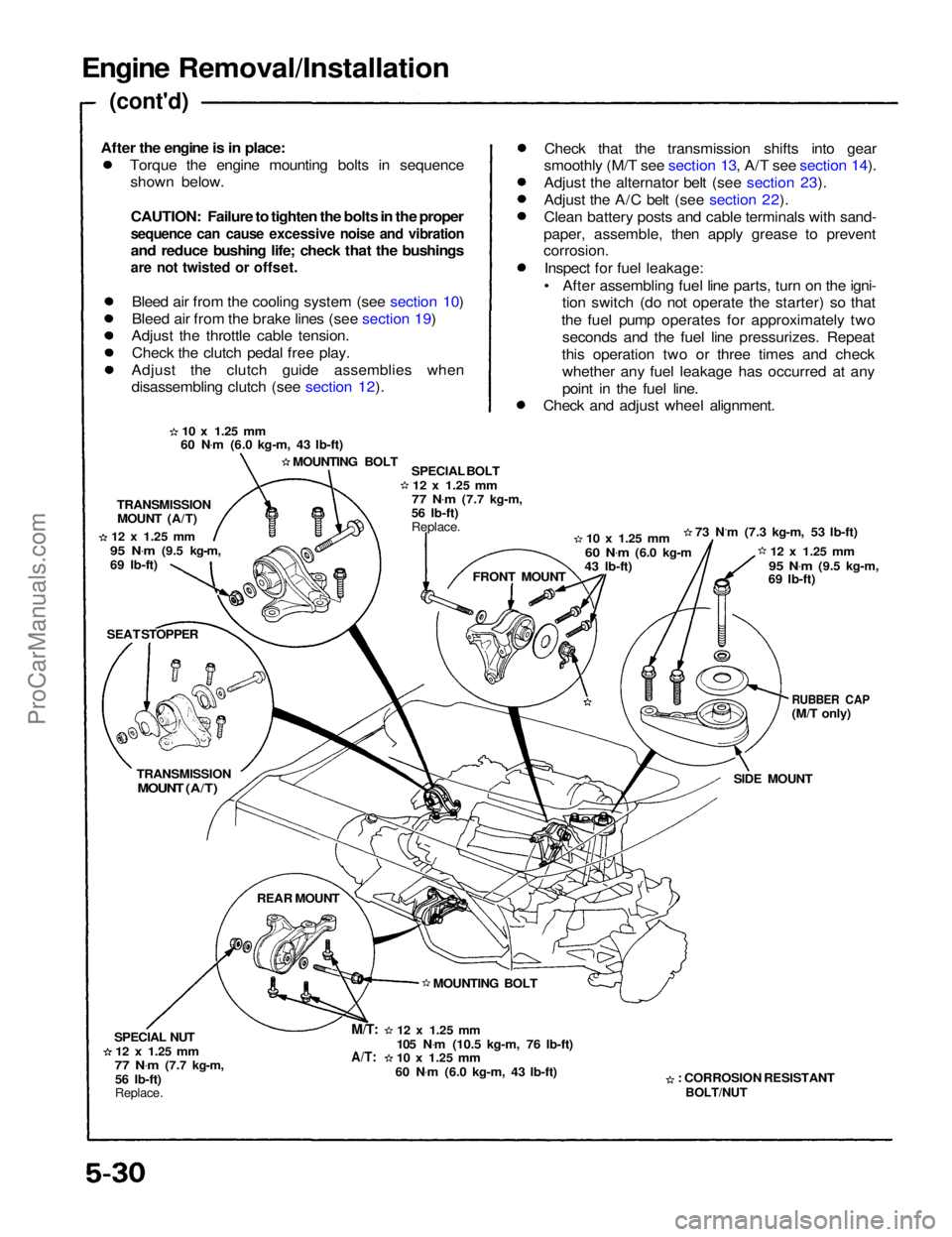
Torque the engine mounting bolts in sequenceshown below.
CAUTION: Failure to tighten the bolts in the proper
sequence can cause excessive noise and vibration
and reduce bushing life; check that the bushings
are not twisted or offset.
Bleed air from the cooling system (see section 10)
Bleed air from the brake lines (see section 19)
Adjust the throttle cable tension.
Check the clutch pedal free play.
Adjust the clutch guide assemblies when
disassembling clutch (see section 12). Check that the transmission shifts into gear
smoothly (M/T see section 13, A/T see section 14).
Adjust the alternator belt (see section 23).
Adjust the A/C belt (see section 22).
Clean battery posts and cable terminals with sand-
paper, assemble, then apply grease to prevent
corrosion.
Inspect for fuel leakage:
• After assembling fuel line parts, turn on the igni- tion switch (do not operate the starter) so that
the fuel pump operates for approximately two seconds and the fuel line pressurizes. Repeat
this operation two or three times and check whether any fuel leakage has occurred at any
point in the fuel line.
Check and adjust wheel alignment.
10 x
1.25
mm
60 N .
m (6.0 kg-m, 43 Ib-ft)
MOUNTING BOLT SPECIAL BOLT
12 x
1.25
mm
77 N .
m
(7.7 kg-m,
56 Ib-ft)
Replace.
10 x
1.25
mm
60 N .
m
(6.0 kg-m
43 Ib-ft) 73 N.m (7.3 kg-m, 53 Ib-ft)
12 x
1.25
mm
95 N .
m
(9.5 kg-m,
69 Ib-ft)
RUBBER CAP
(M/T only)
SIDE MOUNT
: CORROSION RESISTANT
BOLT/NUT
12 x
1.25
mm
105 N .
m (10.5 kg-m, 76 Ib-ft)
10 x
1.25
mm
60 N .
m (6.0 kg-m, 43 Ib-ft) MOUNTING BOLT FRONT MOUNT
TRANSMISSION
MOUNT (A/T)
12 x
1.25
mm
95 N .
m
(9.5 kg-m,
69 Ib-ft)
SEAT STOPPER
TRANSMISSION
MOUNT (A/T)
REAR MOUNT
SPECIAL NUT
12 x
1.25
mm
77 N .
m
(7.7 kg-m,
56 Ib-ft)
Replace.
M/T:
A/T:
After the engine is in place:ProCarManuals.com
Page 1014 of 1640
Cylinder Heads
Removal
Engine removal is not required in this procedure.
CAUTION: To avoid damaging the cylinder heads, wait until the engine coolant temperature drops below 100°F (38°C) before loosening the retaining bolts.
NOTE:
Inspect the timing belt before removing the cylinder
heads.
Turn the crankshaft so that the No. 1 piston is at top
dead center (TDC (page 6-25, 26). Mark all emission hoses before disconnecting them.
1. Disconnect the negative terminal from the battery.
2. Remove the expansion tank cap.
Use care when removing the expan-
sion tank cap to avoid scalding by engine coolant or
steam.
3. Raise the car.
4. Remove the right rear wheel/tire.
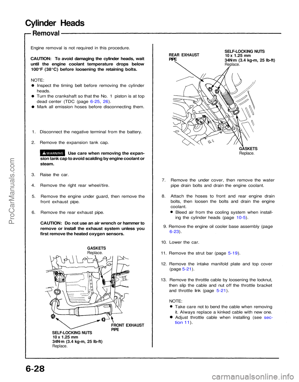
5. Remove the engine under guard, then remove the front exhaust pipe.
6. Remove the rear exhaust pipe.
CAUTION: Do not use an air wrench or hammer to
remove or install the exhaust system unless you
first remove the heated oxygen sensors.
GASKETS
Replace.
FRONT EXHAUST
PIPE
SELF-LOCKING NUTS
10 x
1.25
mm
34N .
m (3.4 kg-m, 25 Ib-ft)
Replace.
REAR EXHAUST
PIPE
SELF-LOCKING NUTS
10 x
1.25
mm
34N .
m (3.4 kg-m, 25 Ib-ft)
Replace.
GASKETS
Replace.
7. Remove the under cover, then remove the water pipe drain bolts and drain the engine coolant.
8. Attach the hoses to front and rear engine drain bolts, then loosen the bolts and drain the engine
coolant.
Bleed air from the cooling system when install-
ing the cylinder heads (page 10-5).
9. Remove the engine oil cooler base assembly (page
6-23).
10. Lower the car.
11. Remove the strut bar (page 5-19).
12. Remove the intake manifold plate and top cover (page 5-21).
13. Remove the throttle cable by loosening the locknut, then slip the cable and nut off the throttle bracketand throttle link (page 5-21).
NOTE:
Take care not to bend the cable when removingit. Always replace a kinked cable with new one.Adjust throttle cable when installing (see sec-
tion 11).ProCarManuals.com
Page 1085 of 1640
3. Fuel Cut-off Control
During deceleration with the throttle valve closed, current to the fuel injectors is cut off to improve fuel economy
at speeds over 1,500 rpm.
Fuel cut-off action also takes place when engine speed exceeds, 8,300 rpm, regardless of the position of the
throttle valve, to protect the engine from over-revving.
4. A/C Compressor Clutch Relay
When the ECM receives a demand for cooling from the air conditioning system, it delays the compressor from being
energized, and enriches the mixture to assure smooth translation to the A/C mode.
5. Evaporative Emission (EVAP) Purge Control Solenoid Valve
When the engine coolant temperature is below 1 58 °F (70°C) the ECM supplies a ground to the EVAP purge control
solenoid valve which cuts vacuum to the EVAP purge control diaphragm valve.
6. Intake Air Bypass (IAB) Control Solenoid Valve
When the engine speed is below 4,800 rpm, the IAB control solenoid valve is activated by a signal from the ECM.
Intake air then flows through the smaller chamber, and hight torque is delivered. To increase air flow at engine speeds
higher than 4,800 rpm, the solenoid valve is deactivated by the ECM, and the intake air flows through the larger
chamber.
7. Exhaust Gas Recirculation (EGR) Control Solenoid Valve
When the EGR is required for control of oxides of nitrogen (NOx) emissions, the ECM supplies ground to the EGR
control solenoid valve which supplies regulated vacuum to the EGR valve.
ECM fail-safe/back-up Functions
1. Fail-Safe Function
When an abnormality occurs in a signal from a sensor, the ECM ignores that signal and assumes a pre-programmed
valve for that sensor that allows the engine to continue to run.
2. Back-up Function
When an abnormality occurs in the ECM itself, the fuel injectors are controlled by a back-up circuit independent of
the system in order to permit minimal driving.
3. Self-diagnosis Function [Malfunction Indicator Lamp (MIL)]
When an abnormality occurs in a signal from a sensor, the ECM lights the MIL and stores the diagnostic trouble code
in erasable memory. When the ignition is initially turned in, the ECM supplies ground for the MIL for two seconds
to check the MIL bulb condition.ProCarManuals.com
Page 1095 of 1640
Idle Control System
Troubleshooting Flowchart
Air Conditioning Signal
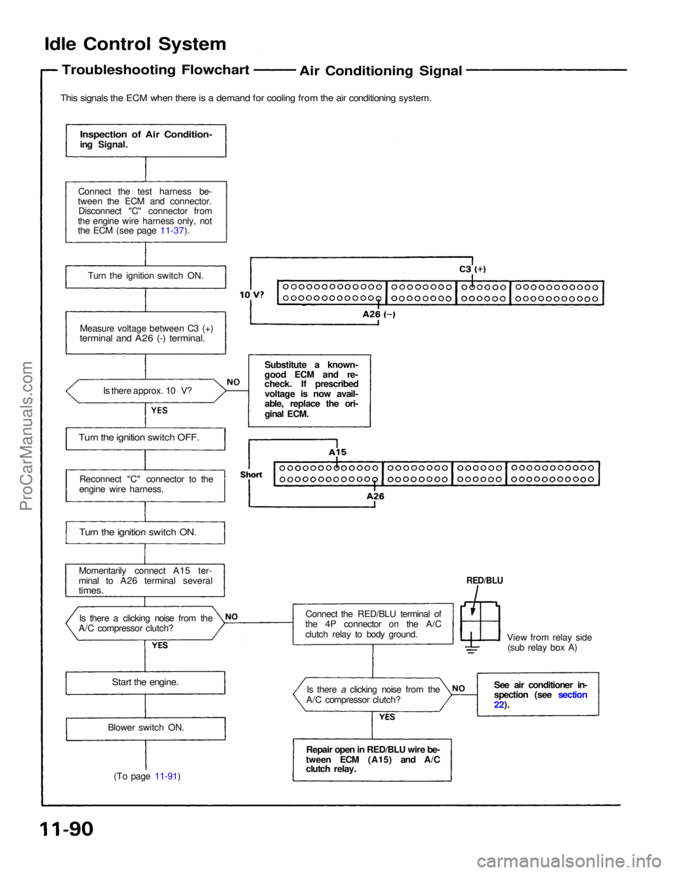
This signals the ECM when there is a demand for cooling from the air conditioning system.
Inspection of Air Condition-
ing Signal.
Connect the test harness be-
tween the ECM and connector. Disconnect "C" connector from
the engine wire harness only, not
the ECM (see page 11-37).
Turn the ignition switch ON.
Measure voltage between C3 (+)
terminal and A26 (-) terminal.
Is there approx. 10 V?
Turn the ignition switch OFF.
Reconnect "C" connector to the
engine wire harness.
Turn the ignition switch ON.
Momentarily connect A15 ter-
minal to A26 terminal several
times.
Is there a clicking noise from the
A/C compressor clutch?
Start the engine.
Blower switch ON.
(To page 11-91) Repair open in RED/BLU wire be-
tween ECM (A15) and A/C
clutch relay. Is there a clicking noise from the
A/C compressor clutch?
Connect the RED/BLU terminal of
the 4P connector on the A/C
clutch relay to body ground. View from relay side
(sub relay box A)
RED/BLU
See air conditioner in-
spection (see section
22).
Substitute a known-
good ECM and re-
check. If prescribed
voltage is now avail-
able, replace the ori-
ginal ECM.ProCarManuals.com
Page 1097 of 1640
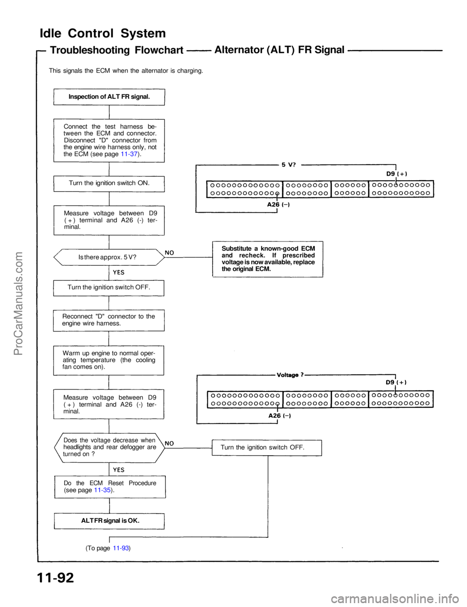
Idle Control System
Troubleshooting Flowchart
Alternator (ALT) FR Signal
This signals the ECM when the alternator is charging.
Inspection of ALT FR signal.
Connect the test harness be-
tween the ECM and connector.
Disconnect "D" connector from
the engine wire harness only, not
the ECM (see page 11-37).
Turn the ignition switch ON.
Measure voltage between D9 ( + ) terminal and A26 (-) ter-
minal.
Is there approx. 5 V?
Turn the ignition switch OFF.
Reconnect "D" connector to the
engine wire harness.
Warm up engine to normal oper-ating temperature (the cooling
fan comes on).
Measure voltage between D9( + ) terminal and A26 (-) ter-
minal.
Does the voltage decrease when
headlights and rear defogger are
turned on ?
Do the ECM Reset Procedure
(see page 11-35).
ALT FR signal is OK.(To page 11-93) Substitute a known-good ECM
and recheck. If prescribed
voltage is now available, replace
the original ECM.
Turn the ignition switch OFF.ProCarManuals.com
Page 1105 of 1640
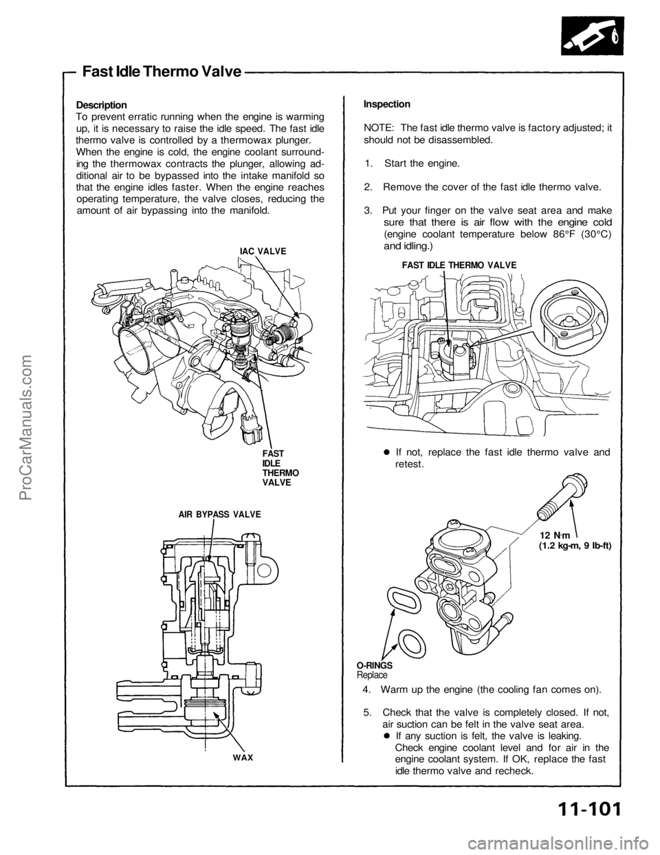
Fast Idle Thermo Valve
Description
To prevent erratic running when the engine is warming
up, it is necessary to raise the idle speed. The fast idle
thermo valve is controlled by a thermowax plunger.
When the engine is cold, the engine coolant surround-ing the thermowax contracts the plunger, allowing ad-
ditional air to be bypassed into the intake manifold so
that the engine idles faster. When the engine reaches operating temperature, the valve closes, reducing theamount of air bypassing into the manifold.
IAC VALVE
FAST
IDLE
THERMO
VALVE
AIR BYPASS VALVE
WAX
Inspection
NOTE: The fast idle thermo valve is factory adjusted; it
should not be disassembled. 1. Start the engine.
2. Remove the cover of the fast idle thermo valve.
3. Put your finger on the valve seat area and make
sure that there is air flow with the engine cold
(engine coolant temperature below 86°F (30°C)
and idling.)
FAST IDLE THERMO VALVE
If not, replace the fast idle thermo valve and
retest.
12 N.
m
(1.2 kg-m, 9 Ib-ft)
O-RINGS
Replace
4. Warm up the engine (the cooling fan comes on).
5. Check that the valve is completely closed. If not, air suction can be felt in the valve seat area.If any suction is felt, the valve is leaking.
Check engine coolant level and for air in the
engine coolant system. If OK, replace the fast idle thermo valve and recheck.ProCarManuals.com
Page 1106 of 1640
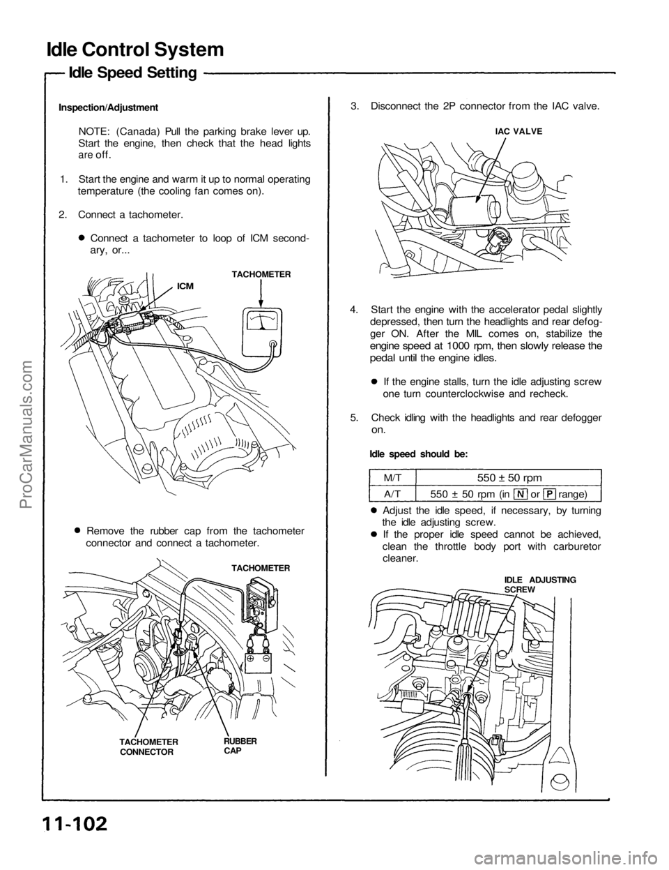
Idle Control System
Idle Speed Setting
Inspection/Adjustment NOTE: (Canada) Pull the parking brake lever up.
Start the engine, then check that the head lights
are
off.
1. Start the engine and warm it up to normal operating temperature (the cooling fan comes on).
2. Connect a tachometer. Connect a tachometer to loop of ICM second-
ary, or...
TACHOMETER
ICM
Remove the rubber cap from the tachometer
connector and connect a tachometer.
TACHOMETER
TACHOMETER CONNECTOR
RUBBER
CAP
3. Disconnect the 2P connector from the IAC valve.
IAC VALVE
4. Start the engine with the accelerator pedal slightly depressed, then turn the headlights and rear defog-
ger ON. After the MIL comes on, stabilize the
engine speed at 1000 rpm, then slowly release the
pedal until the engine idles.
If the engine stalls, turn the idle adjusting screw
one turn counterclockwise and recheck.
5. Check idling with the headlights and rear defogger
on.
Idle speed should be:
M/T
A/T
550 ± 50 rpm
550 ± 50 rpm (in or range)
Adjust the idle speed, if necessary, by turning
the idle adjusting screw.
If the proper idle speed cannot be achieved,
clean the throttle body port with carburetor
cleaner.
IDLE ADJUSTING
SCREWProCarManuals.com
Page 1107 of 1640
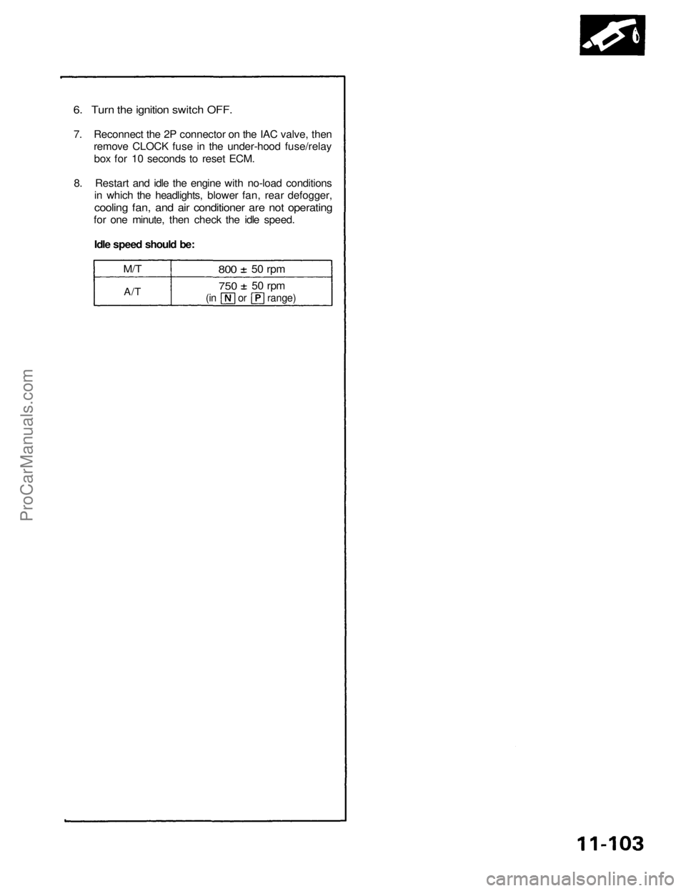
6. Turn the ignition switch OFF.
7. Reconnect the 2P connector on the IAC valve, then
remove CLOCK fuse in the under-hood fuse/relay
box for 10 seconds to reset ECM.
8. Restart and idle the engine with no-load conditions
in which the headlights, blower fan, rear defogger,
cooling fan, and air conditioner are not operating
for one minute, then check the idle speed.
Idle speed should be:
M/T
A/T
800
50 rpm
750
50 rpm
(in or range)ProCarManuals.com