Page 307 of 1640
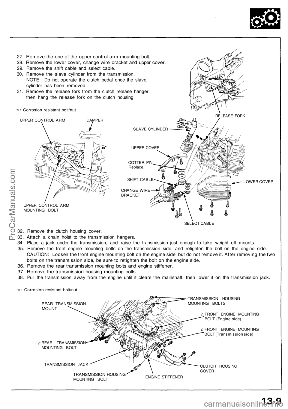
27. Remove the one of the upper control arm mounting bolt.
28. Remove the lower cover, change wire bracket and upper cover.
29. Remove the shift cable and select cable.
30. Remove the slave cylinder from the transmission.
NOTE: Do not operate the clutch pedal once the slave
cylinder has been removed.
31. Remove the release fork from the clutch release hanger,
then hang the release fork on the clutch housing.
Corrosion resistant bolt/nut
UPPER CONTROL ARM DAMPER
SLAVE CYLINDER
UPPER COVER
COTTER PIN
Replace.
SHIFT CABLE
CHANGE WIRE
BRACKET
UPPER CONTROL ARM
MOUNTING BOLT
LOWER COVER
SELECT CABLE
32. Remove the clutch housing cover.
33. Attach a chain hoist to the transmission hangers.
34. Place a jack under the transmission, and raise the transmission just enough to take weight off mounts.
35. Remove the front engine mounting bolts on the transmission side, and retighten the bolt on the engine side.
CAUTION: Loosen the front engine mounting bolt on the engine side, but do not remove it. After removing the two
bolts on the transmission side, be sure to retighten the bolt on the engine side.
36. Remove the rear transmission mounting bolts and engine stiffener.
37. Remove the transmission housing mounting bolts.
38. Pull the transmission away from the engine until it clears the mainshaft, then lower it on the transmission jack.
Corrosion resistant bolt/nut
REAR TRANSMISSION
MOUNT
REAR TRANSMISSION
MOUNTING BOLT
TRANSMISSION JACK
TRANSMISSION HOUSING
MOUNTING BOLTS
FRONT ENGINE MOUNTING
BOLT (Engine side)
FRONT ENGINE MOUNTING
BOLT (Transmission side)
TRANSMISSION HOUSING
MOUNTING BOLT
CLUTCH HOUSING
COVER
ENGINE STIFFENER
RELEASE FORKProCarManuals.com
Page 310 of 1640
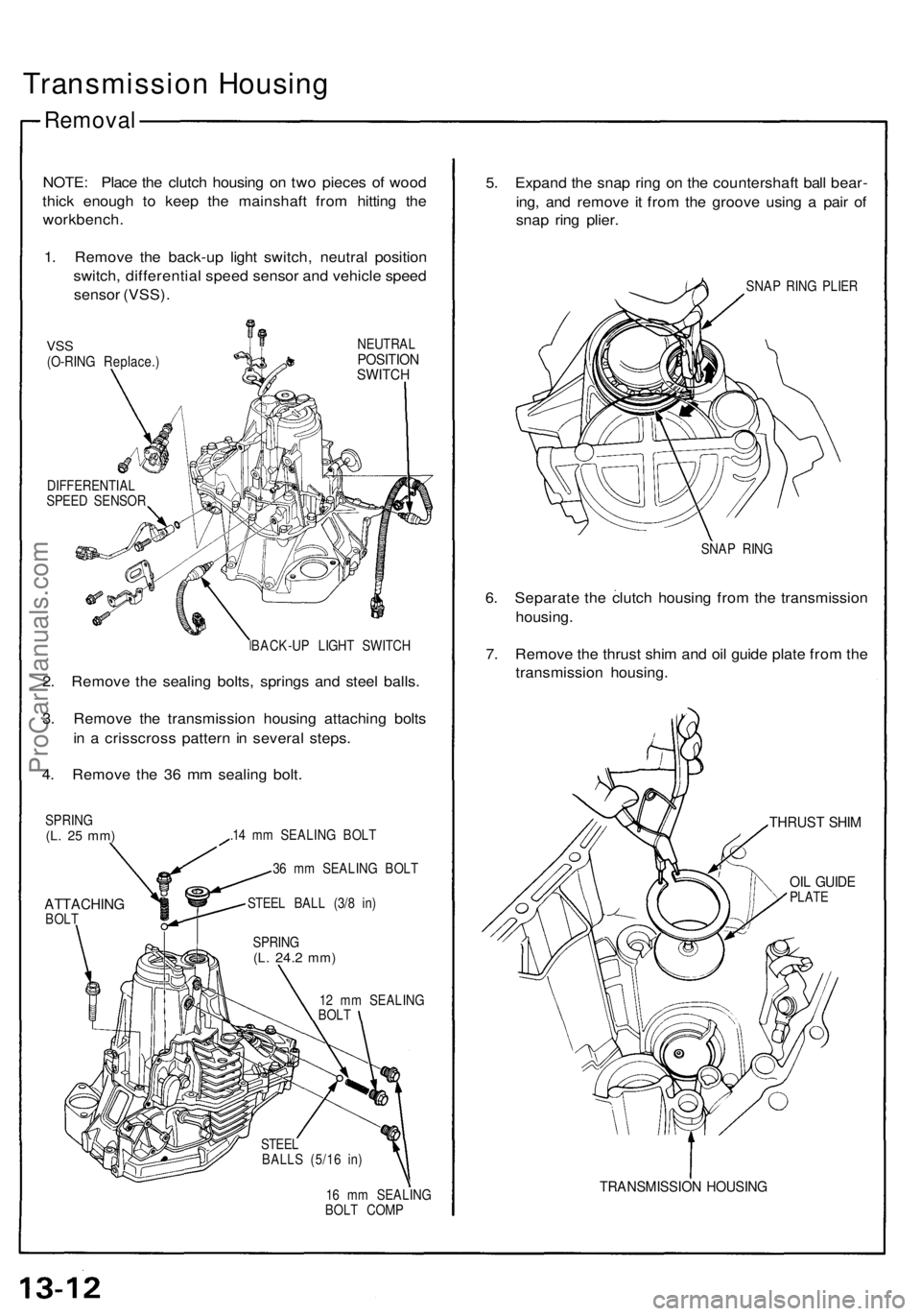
Transmission Housing
Removal
NOTE: Place the clutch housing on two pieces of wood
thick enough to keep the mainshaft from hitting the
workbench.
1. Remove the back-up light switch, neutral position
switch, differential speed sensor and vehicle speed
sensor (VSS).
VSS
(O-RING Replace.)
NEUTRAL
POSITION
SWITCH
DIFFERENTIAL
SPEED SENSOR
BACK-UP LIGHT SWITCH
2. Remove the sealing bolts, springs and steel balls.
3. Remove the transmission housing attaching bolts
in a crisscross pattern in several steps.
4. Remove the 36 mm sealing bolt.
SPRING
(L. 25 mm)
ATTACHING
BOLT
.14 mm SEALING BOLT
36 mm SEALING BOLT
STEEL BALL (3/8 in)
12 mm SEALING
BOLT
16 mm SEALING
BOLT COMP
5. Expand the snap ring on the countershaft ball bear-
ing, and remove it from the groove using a pair of
snap ring plier.
SNAP RING PLIER
SNAP RING
6. Separate the clutch housing from the transmission
housing.
7. Remove the thrust shim and oil guide plate from the
transmission housing.
THRUST SHIM
OIL GUIDE
PLATE
TRANSMISSION HOUSING
SPRING
(L.
24.2
mm)
STEEL
BALLS (5/16 in)ProCarManuals.com
Page 318 of 1640
Shift Lever,
Select Lever
Removal
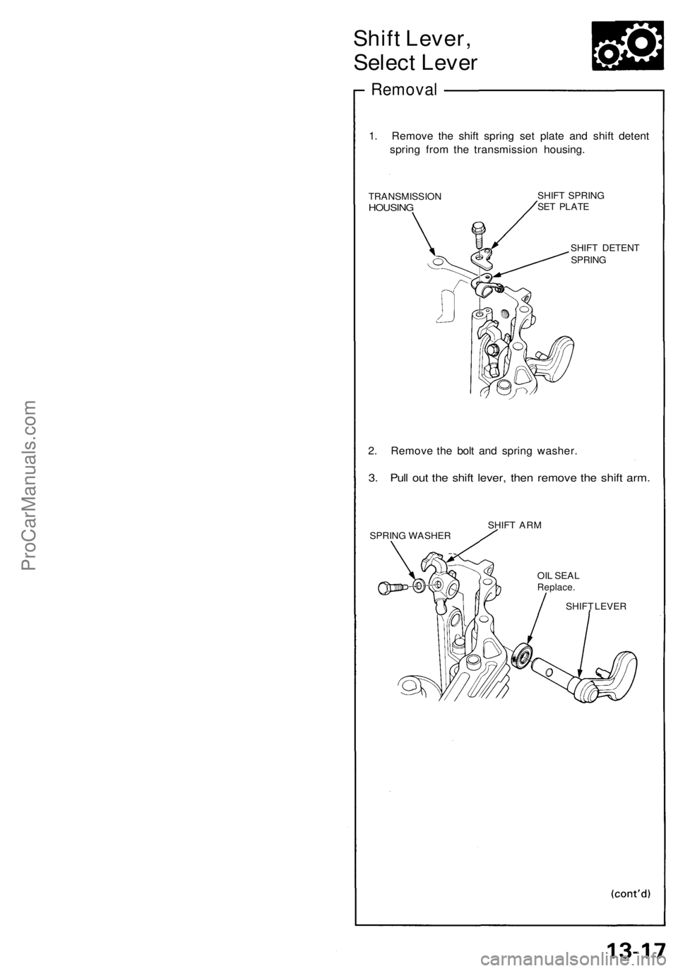
1. Remove the shift spring set plate and shift detent
spring from the transmission housing.
TRANSMISSION
HOUSING
SHIFT SPRING
SET PLATE
SHIFT DETENT
SPRING
2. Remove the bolt and spring washer.
3. Pull out the shift lever, then remove the shift arm.
SPRING WASHER
SHIFT ARM
SHIFT LEVER
OIL SEAL
Replace.ProCarManuals.com
Page 328 of 1640
Disassembly
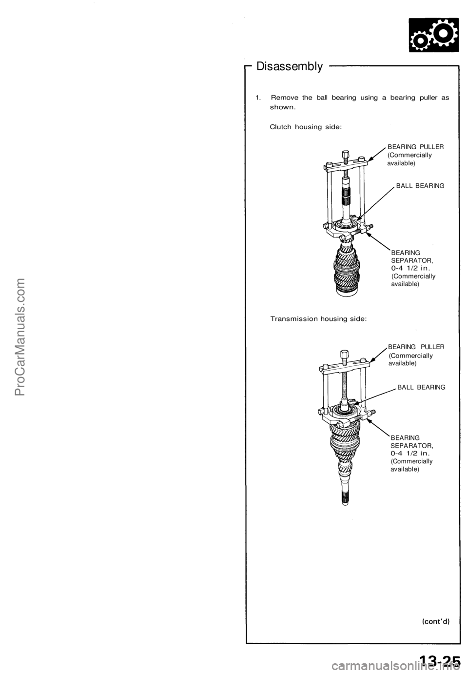
1. Remove the ball bearing using a bearing puller as
shown.
Clutch housing side:
Transmission housing side:
BEARING PULLER
(Commercially
available)
BALL BEARING
BEARING
SEPARATOR,
0-4 1/2 in.
(Commercially
available)
BEARING PULLER
(Commercially
available)
BALL BEARING
BEARING
SEPARATOR,
0-4 1/2 in.
(Commercially
available)ProCarManuals.com
Page 342 of 1640
Oil Pump
Clearance Inspection
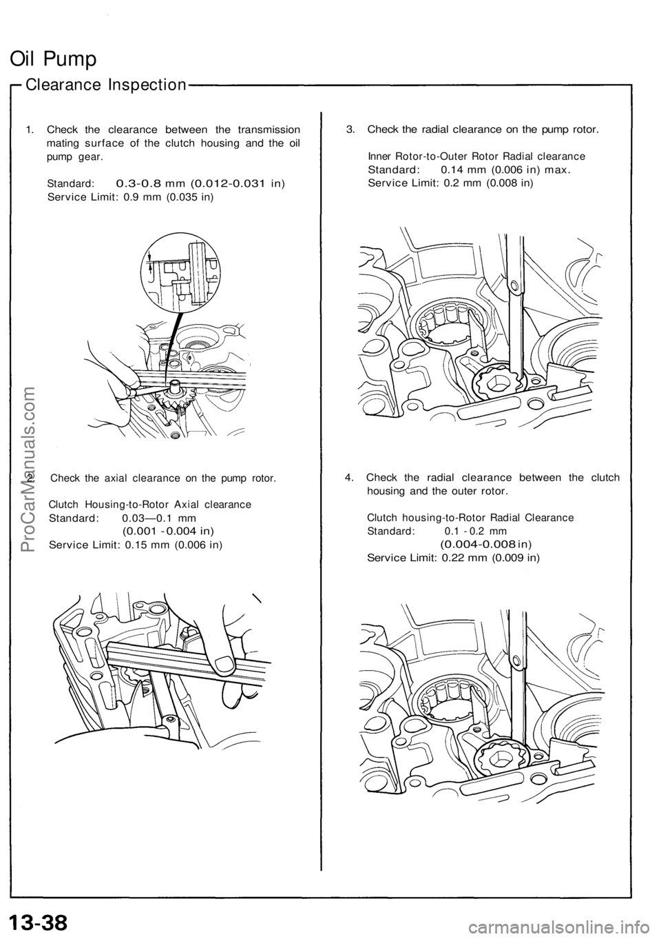
1. Check the clearance between the transmission
mating surface of the clutch housing and the oil
pump gear.
Standard:
0.3-0.8
mm
(0.012-0.031
in)
Service Limit: 0.9 mm (0.035 in)
2. Check the axial clearance on the pump rotor.
Clutch Housing-to-Rotor Axial clearance
Standard: 0.03—0.1 mm
(0.001 - 0.004 in)
Service Limit: 0.15 mm (0.006 in)
3. Check the radial clearance on the pump rotor.
Inner Rotor-to-Outer Rotor Radial clearance
Standard: 0.14 mm (0.006 in) max.
Service Limit: 0.2 mm (0.008 in)
4. Check the radial clearance between the clutch
housing and the outer rotor.
Clutch housing-to-Rotor Radial Clearance
Standard: 0.1 - 0.2 mm
(0.004-0.008
in)
Service Limit: 0.22 mm (0.009 in)ProCarManuals.com
Page 345 of 1640
Mainshaft Thrust Shim
Adjustment
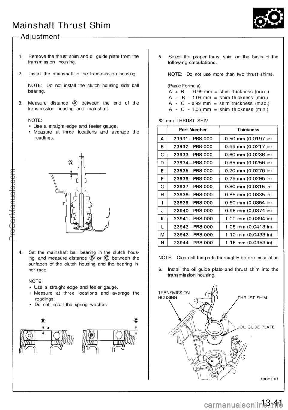
1. Remove the thrust shim and oil guide plate from the
transmission housing.
2. Install the mainshaft in the transmission housing.
NOTE: Do not install the clutch housing side ball
bearing.
3. Measure distance between the end of the
transmission housing and mainshaft.
NOTE:
• Use a straight edge and feeler gauge.
• Measure at three locations and average the
readings.
4. Set the mainshaft ball bearing in the clutch hous-
ing, and measure distance between the
surfaces of the clutch housing and the bearing in-
ner race.
NOTE:
• Use a straight edge and feeler gauge.
• Measure at three locations and average the
readings.
• Do not install the spring washer.
5. Select the proper thrust shim on the basis of the
following calculations.
NOTE: Do not use more than two thrust shims.
(Basic Formula)
A + B — 0.99 mm = shim thickness (max.)
A + B - 1.06 mm = shim thickness (min.)
A - C - 0.99 mm = shim thickness (max.)
A - C - 1.06 mm = shim thickness (min.)
82 mm THRUST SHIM
NOTE: Clean all the parts thoroughly before installation
6. Install the oil guide plate and thrust shim into the
transmission housing.
TRANSMISSION
HOUSING
THRUST SHIM
OIL GUIDE PLATE
13-41ProCarManuals.com
Page 346 of 1640
Mainshaft Thrus t Shi m
Adjustmen t
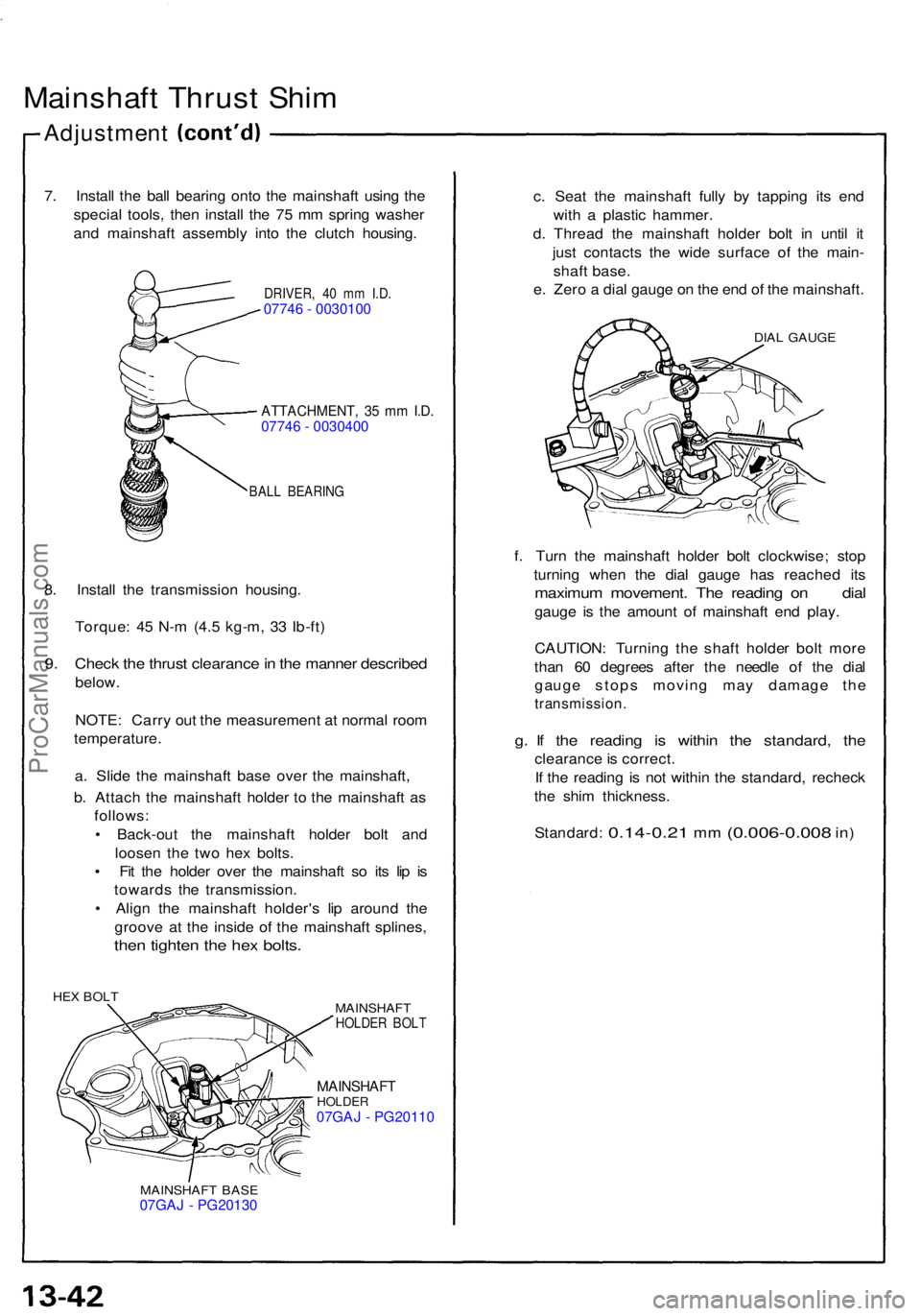
7. Instal l th e bal l bearin g ont o th e mainshaf t usin g th e
specia l tools , the n instal l th e 7 5 m m sprin g washe r
an d mainshaf t assembl y int o th e clutc h housing .
DRIVER, 4 0 m m I.D .07746 - 0030100
ATTACHMENT , 3 5 m m I.D .07746 - 0030400
BAL L BEARIN G
8. Instal l th e transmissio n housing .
Torque : 4 5 N- m (4. 5 kg-m , 3 3 Ib-ft )
9. Chec k th e thrus t clearanc e in th e manne r describe d
below.
NOTE : Carr y ou t th e measuremen t a t norma l roo m
temperature .
a . Slid e th e mainshaf t bas e ove r th e mainshaft ,
b . Attac h th e mainshaf t holde r t o th e mainshaf t a s
follows :
• Back-ou t th e mainshaf t holde r bol t an d
loose n th e tw o he x bolts .
• Fi t th e holde r ove r th e mainshaf t s o it s li p i s
toward s th e transmission .
• Alig n th e mainshaf t holder' s li p aroun d th e
groov e a t th e insid e of the mainshaf t splines ,
then tighte n th e he x bolts .
HEX BOL T
MAINSHAFT
HOLDER BOL T
MAINSHAF THOLDER07GAJ - PG20110
MAINSHAF T BAS E07GAJ - PG20130
c. Sea t th e mainshaf t full y b y tappin g it s en d
wit h a plasti c hammer .
d . Threa d th e mainshaf t holde r bol t i n unti l i t
jus t contact s th e wid e surfac e o f th e main -
shaf t base .
e . Zer o a dia l gaug e o n th e en d o f th e mainshaft .
DIAL GAUG E
f. Tur n th e mainshaf t holde r bol t clockwise ; sto p
turnin g whe n th e dia l gaug e ha s reache d it s
maximu m movement . Th e readin g o n dia l
gauge i s th e amoun t o f mainshaf t en d play .
CAUTION : Turnin g th e shaf t holde r bol t mor e
tha n 6 0 degree s afte r th e needl e o f th e dia l
gaug e stop s movin g ma y damag e th e
transmission .
g. I f th e readin g i s withi n th e standard , th e
clearanc e is correct .
I f th e readin g i s no t withi n th e standard , rechec k
th e shi m thickness .
Standard :
0.14-0.21 mm (0.006-0.00 8 in)
ProCarManuals.com
Page 347 of 1640
Transmission
Reassembly
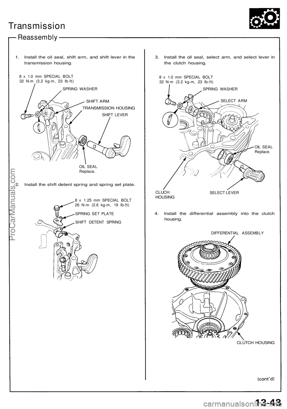
1. Install the oil seal, shift arm, and shift lever in the
transmission housing.
8 x 1.0 mm SPECIAL BOLT
32 N-m (3.2 kg-m, 23 Ib-ft)
SPRING WASHER
SHIFT ARM
TRANSMISSION HOUSING
SHIFT LEVER
OIL SEAL
Replace.
2. Install the shift detent spring and spring set plate.
8 x 1.25 mm SPECIAL BOLT
26 N-m (2.6 kg-m, 19 Ib-ft)
SPRING SET PLATE
SHIFT DETENT SPRING
3. Install the oil seal, select arm, and select lever in
the clutch housing.
8 x 1.0 mm SPECIAL BOLT
32 N-m (3.2 kg-m, 23 Ib-ft)
SPRING WASHER
SELECT ARM
OIL SEAL
Replace.
CLUCH
HOUSING
SELECT LEVER
4. Install the differential assembly into the clutch
housing.
DIFFERENTIAL ASSEMBLY
CLUTCH HOUSINGProCarManuals.com