1990 VOLKSWAGEN TRANSPORTER heating
[x] Cancel search: heatingPage 4 of 165

Downloaded from www.Manualslib.com manuals search engine
1
INSTRUMENT PANEL
Illustration instruments and controls
Warning and indicator light symbols
CONTROLS AND EQUIPMENT
Keys,
central locking system .... 7, 8
Doors 9
Rear lid 11
Windows, mirrors 12, 13 Safety belts, head restraints . . . .14,19
Seats 20 Luggage compartment, pedals . 28,29
Brakes, Transmission 29, 32 Differential lock 33
Automatic-transmission 35 Steering lock/ignition/starter switch . 38
Starting procedures 39 Instrument cluster 40
Warning/indicator lights 43 Switches 46 Emergency flasher 46
Light switch, turn signals .... 46,48
Cruise control 49
Windshield wipers 50 Ventilation/Heating 51
Air conditioning 54
Heater 57
Sliding roof 62
Roof-rack 68 VEHICLE OPERATION
Break-in period - and afterwards . . 69
Operate your vehicle safety 70
Operate your vehicle economically
and minimize pollution 72
Trailer towing 73 Driving with the all-wheel drive ... 75
VEHICLE CARE
Fuel tank, fuel supply 85,86
Vehicle care (exterior/interior) . . 90, 93 Maintenance, inspection intervals . . 95 Engine compartment lid,
engine compartment 97 Lubricants, engine oil 98,99
Engine oil filter 101
Transmission oil 102
Power steering 103
Cooling system 104 Brake fluid 108
Battery 109
Windshield washers/wipers . . . 112,113
Tires/wheels 114 Difficult operating conditions .... 120
Winter driving 121
Accessories 122
DO-IT-YOURSELF SERVICE
Jack and tools 123 Spare wheel 124
Changing a wheel 125 Fuses, bulbs 128, 130 Adjusting headlights
134
Installing,
replacing the radio . . . . 135
Emergency starting 136
Emergency towing 138
Lifting vehicle . . 140
TECHNICAL DESCRIPTION
Engine, transmission 142
Steering,
suspension, brakes,
body, chassis 143 Emission-control-system 144
TECHNICAL DATA
Engine, spark plugs .
V-belts capacities . . Dimensions
Weights
Vehicle identification 146
147
148
150 151
CONSUMER INFORMATION
Service manuals 152
GAS STATION INFORMATION
Location of servicing points 156
ALPHABETICAL INDEX 158
www.westfaliaT3.info - a useful website for owners and enthusiasts of VW Westfalia T25 / T3 Campervans
Page 43 of 165
Downloaded from www.Manualslib.com manuals search engine
CONTROLS
AND
EQUIPMENT
WARNING continned •
The
engine compartment
of any
motor vehicle
is a
potentially hazard
ous
area.
Before you check anything in the engine compartment, stop
the
engine and
let it
cool down. Always
exercise extreme caution when work
ing
one the
engine. Heed
all of the
WARNINGS on page
97.
Reduce the risk
of
scalding from
hot
coolant by following these steps.
• If the coolant reservoir cap must be
removed, wait until
the
engine
has
cooled down.
• Protect face, hands
and
arms
by
covering
the cap
with
a
large, thick
rag
to
protect against escaping fluid
and
steam.
• Carefully and slowly
turn
cap
one
turn
to
allow excess pressure
to es
cape before completely removing
cap.
•
To
help avoid being burned,
do not
spill
antifreeze
or
coolant
on the ex
haust system
or hot
engine parts.
Under
some conditions, the ethylene
glycol
in
engine coolant
is
combusti
ble.
If a
visual check shows that coolant level
and V-belt
are
normal,
but the
warning light continues to
flash,
contact
your
near
est dealer
to
have
the
cause located
and
corrected.
For more details see "Cooling system"
on
page 104.
If the
coolant gauge needle nears
the
upper end
of
the scale and the engine ap
pears
to be
overheating,
turn
off the air
conditioner.
Do
not
install accessories
(fog
lights
or
in
sect screens,
for
example)
on top of the
front
bumper.
They
may
restrict engine
cooling.
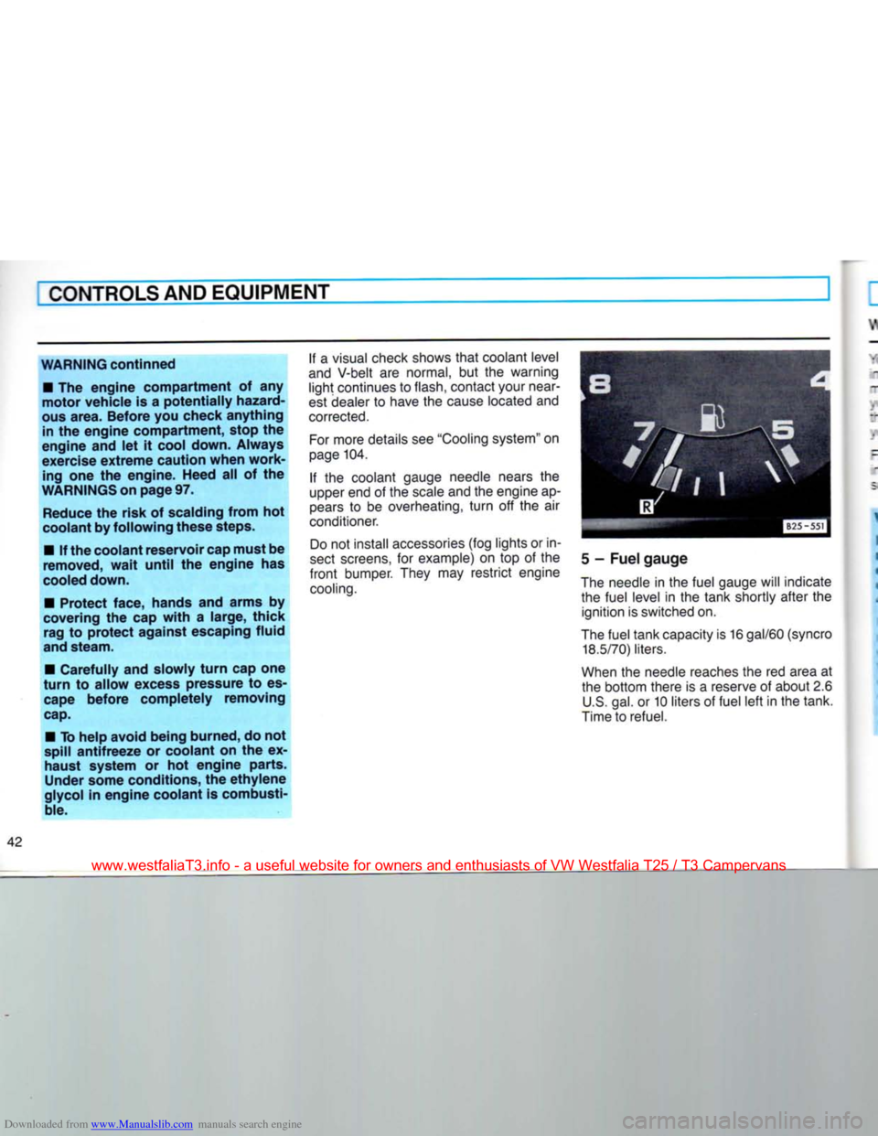
5
-
Fuel gauge
The needle
in
the fuel gauge will indicate the fuel level
in the
tank shortly after
the
ignition is switched on.
The fuel tank capacity is
16
gal/60
(syncro
18.5/70)
liters.
When
the
needle reaches the
red
area
at
the bottom there
is a
reserve
of
about 2.6 U.S. gal.
or
10 liters
of
fuel left in the tank.
Time to refuel.
www.westfaliaT3.info - a useful website for owners and enthusiasts of VW Westfalia T25 / T3 Campervans
Page 48 of 165
Downloaded from www.Manualslib.com manuals search engine
CONTROLS AND
EQUIPMENT
-Rear
window Trm defogger* I I1*
__e
rear window defogger works only
with
re ignition on.
_-e
rear window defogger - together :i the flow through ventilation - will
••= o to keep the inside of the rear window
: ear of condensation and frost.
~~e
rear window defogger is not designed
Of
melting snow. Therefore, always re-
_:ve heavy snow and ice accumulations
refore driving off.
Zepress
the switch to
turn
on the rear * ndow defogger.
~ie control
light
in the switch will
light
• to remind you
that
the defogger is
switched on. After the rear window has
ceen
cleared, switch off the rear window :efogger to avoid unnecessary drain
:i the battery.
By saving electricity, you save fuel. See
aso
page 72.
Vhen
the rear window defogger is
i.vitched on, the outside mirrors
with
;!ectric remote control* are electrically
bated at the same time (see page 13).
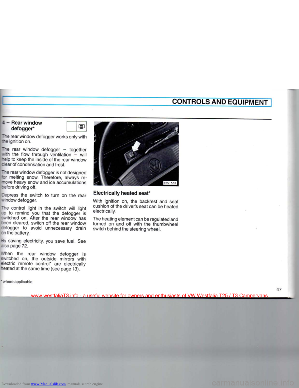
Electrically
heated seat*
With ignition on, the backrest and seat
cushion
of the driver's seat can be heated
electrically.
The heating element can be regulated and turned on and off
with
the thumbwheel switch behind the steering wheel.
where applicable
www.westfaliaT3.info - a useful website for owners and enthusiasts of VW Westfalia T25 / T3 Campervans
Page 52 of 165
Downloaded from www.Manualslib.com manuals search engine
EMULATION/HEATING
CONTROLS
AND EQUIPMENT
I
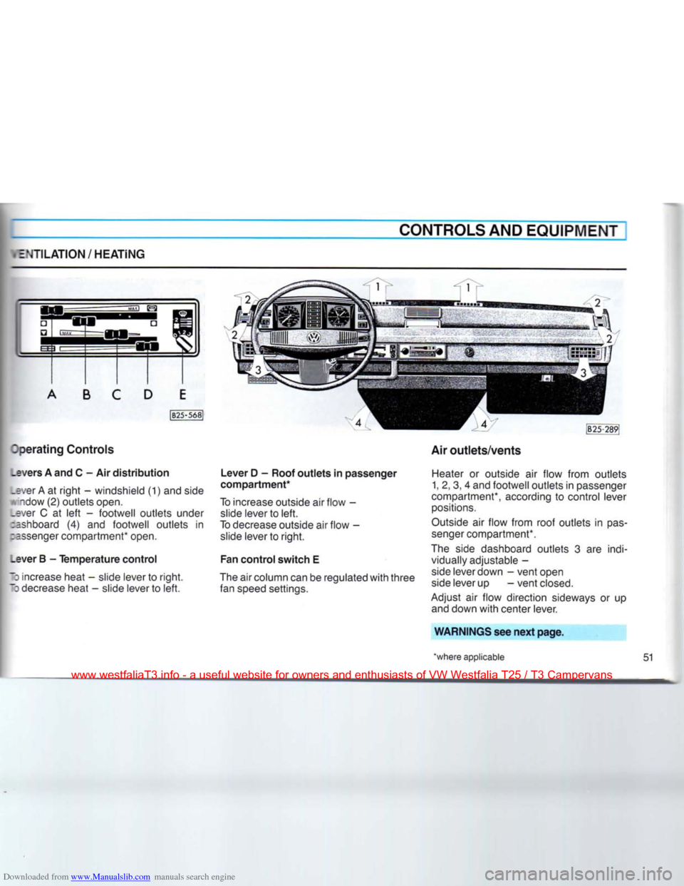
perating
Controls
_evers
A and C - Air
distribution
.ever A at
right
- windshield (1) and side
A'ndow
(2)
outlets
open,
•ver C at
left
-
footwell
outlets
under
:ashboard (4) and
footwell
outlets
in
:=ssenger compartment* open.
_ever
B -
Temperature
control
•
increase heat - slide lever to
right.
~3
decrease heat - slide lever to
left.
Lever
D -
Roof
outlets
in
passenger
compartment*
To increase outside air
flow
- slide lever to
left.
To decrease outside air
flow
- slide lever to
right.
Fan
control
switch
E
The air column can be regulated
with
three
fan speed settings. Air
outlets/vents
Heater or outside air
flow
from
outlets
1, 2, 3, 4 and
footwell
outlets
in passenger
compartment*, according to control lever positions.
Outside air
flow
from
roof
outlets
in
pas
senger compartment*.
The side dashboard
outlets
3 are indi vidually adjustable -
side lever down -
vent
open side lever up
-vent
closed.
Adjust air
flow
direction sideways or up and down
with
center lever.
WARNINGS
see
next
page.
'where
applicable
51
www.westfaliaT3.info - a useful website for owners and enthusiasts of VW Westfalia T25 / T3 Campervans
Page 53 of 165
Downloaded from www.Manualslib.com manuals search engine
CONTROLS
AND EQUIPMENT
WARNING
• Good
visibility
comes
with
windows
free
of
fog,
condensation and
frost.
• For clear
visibility
and safe
driving
it
is
extremely
important
that
you
thor
oughly
familiarize
yourself
with
and fol low the
operating
instructions
pertain
ing to the proper use and
function
of
the
ventilation/heating
and defogging/
defrosting
system in
this
manual. If in
doubt,
consult your Volkswagen
dealer.
•
Maximum
heating
output
and
fast
defrosting
can be
obtained
only
after
the
engine
has reached
operating
tem
perature.
Defogging and
defrosting
wind
shield and side
windows
• Slide all control levers to the extreme
right and
turn
fan control switch E to speed
setting 2.
• The fan control switch for the
secon
dary heat exchanger should be
OFF.
Warming
up vehicle
interior
quickly • Slide levers
A,
B and D to extreme right.
• Slide lever C to extreme left.
• Open air outlets 3.
• Turn fan control switch E to speed
setting 2.
Warming
up vehicle
interior
normally
Once
the windshield and side windows
are
clear and the vehicle interior is warm,
you may want to set the controls as fol
lows:
• Slide lever A to the left.
• Slide lever B to desired temperature
setting.
• Slide lever C toward center.
• Turn fan control switch E to speed
setting 1.
Outside air
ventilation
With lever B at extreme left, outside air is emitted from all open outlets.
Hints
• All operating controls, except fan
con
trol
switch E and fan control switch for the
secondary
heat exchanger can be ad
justed to any intermediate position.
• Stale air is drawn out of the vehicle
interior through vents on the inside
front
door
panels. The vents can be opened or
closed
by sliding the lever forward or
rearward.
52
www.westfaliaT3.info - a useful website for owners and enthusiasts of VW Westfalia T25 / T3 Campervans
Page 55 of 165
Downloaded from www.Manualslib.com manuals search engine
CONTROLS
AND EQUIPMENT
AIR
CONDITIONER*
WARNING
• Good
visibility
comes
with
windows
free
of fog, condensation and
frost.
• For clear
visibility
and safe
driving
it
is
extremely
important
that
you
thor
oughly
familiarize
yourself
with
and fol low the
operating
instructions
pertain
ing to the proper use and
function
of
the
ventilation/heating,
defogging/de-
frosting
and air conditioning system in
this
manual. If in
doubt,
consult your
Volkswagen
dealer.
The
air conditioning unit is installed under
the roof of the driver's cab. Ten air outlets permit interior cooling throughout the
vehicle.
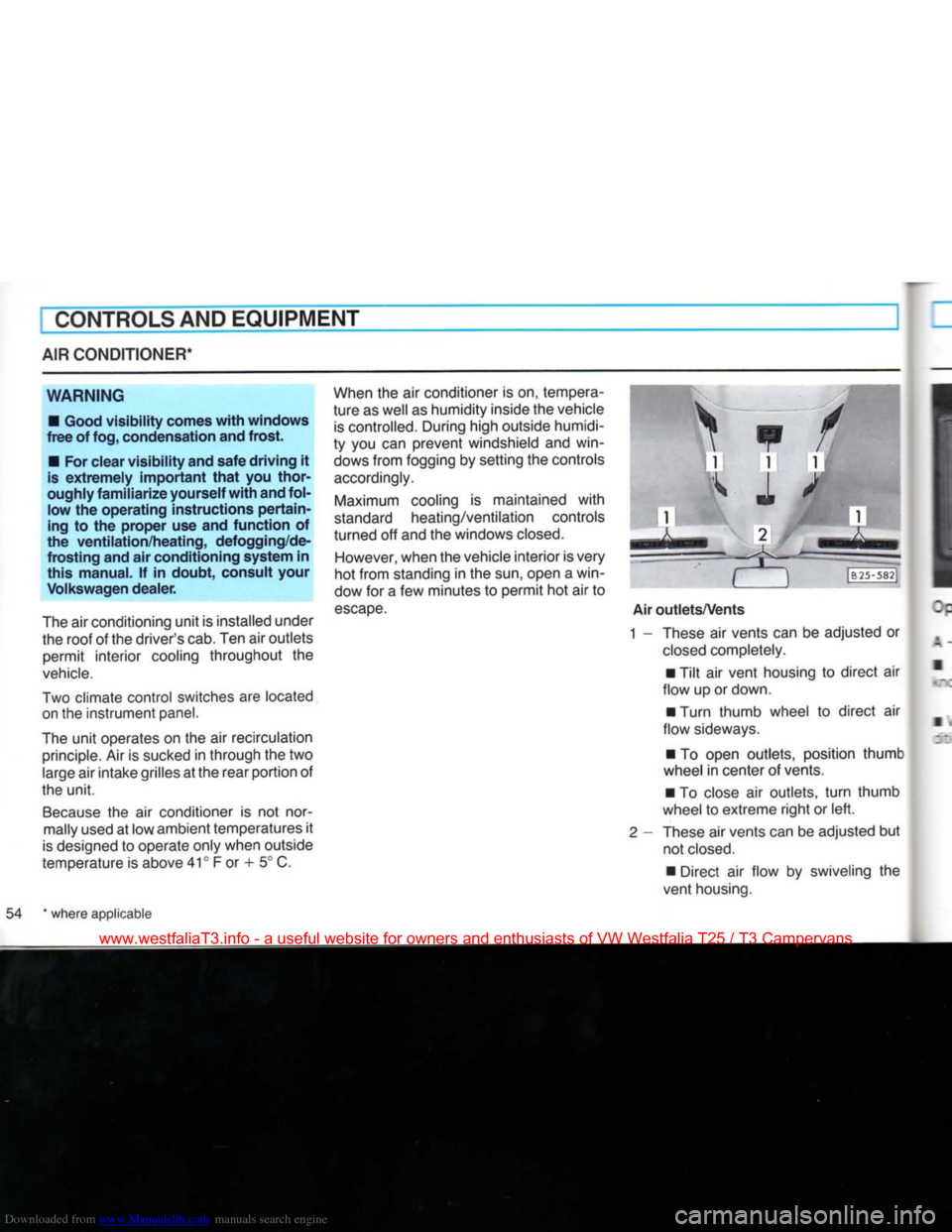
Two
climate control switches are located
on the instrument panel.
The
unit operates on the air recirculation
principle.
Air is sucked in through the two
large
air intake grilles at the rear portion of
the unit.
Because
the air conditioner is not normally used at low ambient temperatures it
is
designed to operate only when outside
temperature is above 41° F or + 5° C.
When
the air conditioner is on, tempera
ture as well as humidity inside the vehicle
is
controlled. During high outside humidi
ty you can prevent windshield and win
dows
from fogging by setting the controls
accordingly.
Maximum
cooling is maintained with
standard
heating/ventilation controls
turned off and the windows
closed.
However,
when the vehicle interior is very
hot from standing in the sun, open a win
dow for a few minutes to permit hot air to
escape.
• iHBll
1
m
Air
outlets/Vents
1 - These air vents can be adjusted or
closed
completely.
• Tilt air vent housing to direct air
flow up or down.
• Turn thumb wheel to direct air
flow sideways.
• To open outlets, position thumb
wheel
in center of vents.
• To close air outlets,
turn
thumb
wheel
to extreme right or left.
2
- These air vents can be adjusted but not
closed.
• Direct air flow by swiveling the
vent housing.
54 * where applicable
www.westfaliaT3.info - a useful website for owners and enthusiasts of VW Westfalia T25 / T3 Campervans
Page 60 of 165
Downloaded from www.Manualslib.com manuals search engine
CONTROLS AND EQUIPMENT
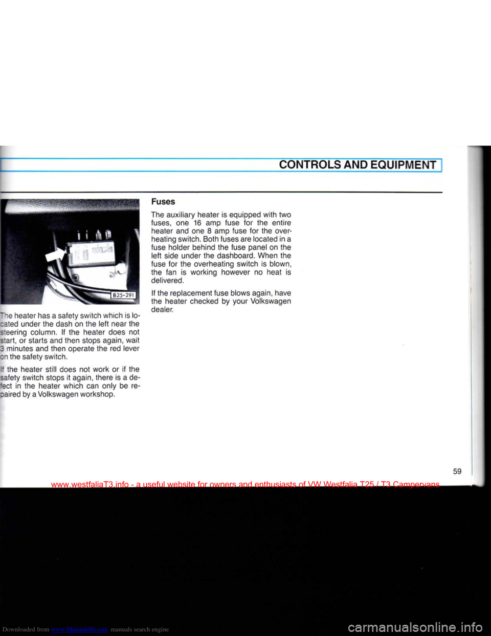
lie heater has a safety switch which is lo- :ated under the dash on the left near the
steering column. If the heater does not
start, or starts and then stops again, wait
3 minutes and then operate the red lever
on the safety switch.
[f the heater still does not work or if the
safety switch stops it again, there is a de-
:ect in the heater which can only be re- :aired by a Volkswagen workshop. Fuses
The auxiliary heater is equipped with two
fuses,
one 16 amp fuse for the entire heater and one 8 amp fuse for the over
heating switch. Both fuses are located in a
fuse holder behind the fuse panel on the left side under the dashboard. When the
fuse for the overheating switch is blown,
the fan is working however no heat is
delivered.
If the replacement fuse blows again, have
the heater checked by your Volkswagen dealer.
59
www.westfaliaT3.info - a useful website for owners and enthusiasts of VW Westfalia T25 / T3 Campervans
Page 61 of 165
Downloaded from www.Manualslib.com manuals search engine
I
CONTROLS AND EQUIPMENT
AUXILIARY HEATER* (Syncro models only)
The auxiliary heater* heats the coolant in the heating circuit and supplies the heat exchanger in the normal heating system
and the additional heat exchanger* for the
passenger compartment heating with heated coolant.
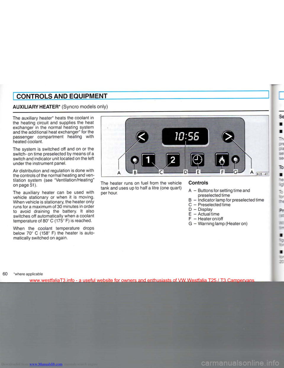
The system is switched off and on or the
switch-
on time preselected by means of a
switch and indicator unit located on the left under the instrument panel.
Air distribution and regulation is done with the controls of the normal heating and
ven
tilation system (see "Ventilation/Heating"
on page 51).
The auxiliary heater can be used with vehicle stationary or when it is moving.
When vehicle is stationary, the heater only runs for a maximum of 30 minutes in order
to avoid draining the battery. It also switches off automatically when a coolant
temperature of 80° C (175° F) is reached.
When the coolant temperature drops below 70° C (158° F) the heater is automatically switched on again. The heater runs on fuel from the vehicle
tank and uses up to half a litre (one quart) per hour. Controls
A - Buttons for setting time and
preselected time
B - Indicator lamp for preselected time
C - Preselected time D - Display
E - Actual time
F - Heater on/off
G - Warning lamp (Heater on)
60 "where applicable
www.westfaliaT3.info - a useful website for owners and enthusiasts of VW Westfalia T25 / T3 Campervans