Page 120 of 165

Downloaded from www.Manualslib.com manuals search engine
VEHICLE CARE
K >i
|B43-155|
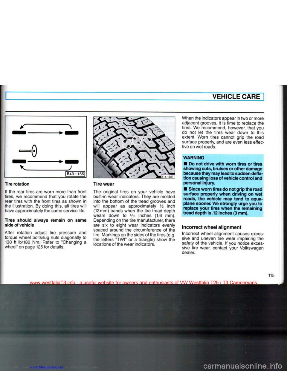
Tire rotation If the
rear tires
are
worn more than
front
tires,
we
recommend
that
you
rotate
the
rear tires
with
the
front
tires
as
shown
in
the illustration.
By
doing this,
all
tires will
have
approximately the same service life.
Tires
should always remain on same
side
of vehicle
After rotation adjust
tire
pressure
and
torque wheel bolts/lug nuts diagonally
to
130
ft
lb/180
Nm.
Refer
to
"Changing
a
wheel"
on page 125
for
details.
Tire
wear
The
original tires
on
your vehicle have
built-in wear indicators. They
are
molded
into
the
bottom
of the
tread grooves
and
will appear
as
approximately
V6
inch (12 mm) bands when
the
tire
tread depth
wears
down
to Vie
inches
(1.6 mm).
Depending
on the
tire
manufacturer, there
are
six to
eight wear indicators evenly
spaced
around
the
circumference
of the
tire. Markings on the sides
of
the tires (e.g.
the letters "TWI"
or a
triangle) show
the
locations
of
the wear indicators.
When
the indicators appear in two
or
more
adjacent grooves,
it is
time
to
replace
the
tires.
We
recommend, however,
that
you
do
not let the
tires wear down
to
this
extent. Worn tires cannot grip
the
road
surface
properly, and are even
less
effec
tive on wet roads.
WARNING
•
Do not drive
with
worn tires or tires
showing
cuts,
bruises
or other damage
because
they may lead to
sudden
defla
tion
causing
loss
of
vehicle
control
and
personal
injury.
•
Since
worn tires do not grip the road
surface
properly when driving on wet
roads,
the vehicle may tend to aqua
plane sooner. We strongly urge you to
replace your tires when the remaining
tread depth is .12
inches
(3 mm).
Incorrect
wheel
alignment
Incorrect wheel alignment
causes
exces
sive
and
uneven
tire
wear impairing
the
safety
of the
vehicle.
If
you notice
exces
sive
tire
wear, contact your Volkswagen
dealer.
115
www.westfaliaT3.info - a useful website for owners and enthusiasts of VW Westfalia T25 / T3 Campervans
Page 132 of 165

Downloaded from www.Manualslib.com manuals search engine
DO-IT-YOURSELF-SERVICE
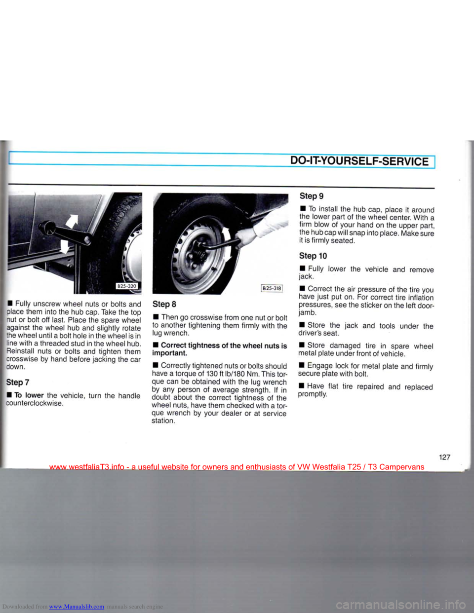
• Fully unscrew wheel nuts or bolts and
dace
them into the hub cap. Take the top
nut or bolt off last.
Place
the spare wheel against the wheel hub and slightly rotate
:he wheel until a bolt hole in the wheel is in ine
with
a threaded stud in the wheel hub.
Reinstall
nuts or bolts and tighten them
crosswise
by hand before jacking the car
down.
Step
7 • To
lower
the vehicle,
turn
the handle
counterclockwise.
Step
8
• Then go crosswise from one nut or bolt
to another tightening them firmly
with
the lug wrench.
• Correct
tightness
of the
wheel
nuts
is
important.
• Correctly tightened nuts or bolts should
have
a torque of 130 ft lb/180 Nm. This
tor
que can be obtained
with
the lug wrench by any person of average strength. If in
doubt about the correct tightness of the
wheel nuts, have them checked
with
a
tor
que wrench by your dealer or at service
station.
Step
9
• To install the hub cap, place it around
the lower part of the wheel center. With a
firm
blow of your hand on the upper part,
the hub cap will snap into place. Make sure it is firmly seated.
Step
10 • Fully lower the vehicle and remove
jack.
• Correct the air pressure of the
tire
you
have
just
put on. For correct
tire
inflation
pressures,
see the sticker on the
left
door-
jamb.
• Store the jack and tools under the
driver's seat.
• Store damaged
tire
in spare wheel
metal plate under
front
of vehicle.
• Engage lock for metal plate and firmly
secure
plate
with
bolt.
• Have
flat
tire
repaired and replaced
promptly.
127
www.westfaliaT3.info - a useful website for owners and enthusiasts of VW Westfalia T25 / T3 Campervans
Page 147 of 165

Downloaded from www.Manualslib.com manuals search engine
I TECHNICAL
DESCRIPTION
ENGINE
MANUAL
TRANSMISSION
AUTOMATIC
TRANSMISSION
• Four stroke gasoline engine in rear.
• Four cylinder horizontally opposed.
• Crankshaft
with
four main bearings.
• Liquid cooling system, thermostatically
controlled.
• Thermoswitch operated electric fan. • Pressure oil feed
with
gear - type
pump and
full
flow
filter.
• Self-adjusting hydraulic valve filters.
• AFC (Airflow controlled) fuel injection.
•
Paper
element air cleaner.
• Exhaust emission control system
with
activated charcoal
filter
in the fuel system.
• Breakerless electronic ignition. • Single plate, dry clutch.
• Synchronized four speed transmission
and'
differential in one housing
with
com
mon lubrication.
•
Rear
wheel drive,
with
two constant
velocity joints per drive shaft.
Syncro • Hydraulically operated single plate
clutch.
• Baulk synchronised 4-speed manual
transmission
with
additional Low-speed
traction gear (4+L transmission).
• Permanent four-wheel drive through
viscous
coupling.
• Manually operated differential lock for
rear final drive available as optional extra. • Hydrodynamic torque converter an:
planetary gearing
with
three forward an:
one reverse gear.
• Final drive in separate housing.
•
Rear
wheel drive,
with
two constar:
velocity joints per drive shaft.
www.westfaliaT3.info - a useful website for owners and enthusiasts of VW Westfalia T25 / T3 Campervans