1990 VOLKSWAGEN CORRADO set
[x] Cancel search: setPage 564 of 906

FUSES & CIRCUIT BREAKERS
Article Text (p. 2)
1990 Volkswagen Corrado
For Volkswagen Technical Site: http://vw.belcom.ru
Copyright © 1998 Mitchell Repair Information Company, LLC
Thursday, March 23, 2000 09:45PM
Right Tail & Side Lights
8 - 10 Amp
Left Tail & Side Lights
9 - 20 Amp
Rear Window & Mirror Heating
10 - 15 Amp
Foglights
11 - 10 Amp
Left High Beam, High Beam Indicator
12 - 10 Amp
Right High Beam
13 - 10 Amp
Horn, Radiator Fan
14 - 15 Amp
Back-Up Lights, Electric Mirrors, Heated Windshield Washer
Jets
15 - 10 Amp
Engine Electronic
16 - 15 Amp
Warning/Indicator Lights, Multi-Function Indicator, Glove Box
Light, Cassette Storage Light, Rear Spoiler
17 - 10 Amp
Turn Signals
18 - 20 Amp
Fuel Pump, Oxygen Sensor
19 - 30 Amp
Radiator Fan, Air Conditioner
20 - 10 Amp
Brakelights, Cruise Control
21 - 15 Amp
Dome & Luggage Compartment Lights, Cigarette Lighter, Central
Locking System, Multi-Function Indicator
22 - 10 Amp
Radio
CAUTIONS & WARNINGS
ELECTRICAL SHOCK
WARNING: Contact with live components of ignition system while
engine is running could lead to a fatal electric shock.
RADIATOR FAN
Keep hands away from radiator fan. Fan is controlled by a
thermostatic switch which may come on or run for up to 15 minutes even
after engine is turned off.
RADIATOR CAP
CAUTION: Always disconnect the fan motor when working near the
radiator fan. The fan is temperature controlled and could
Page 568 of 906

GEAR TOOTH CONTACT PATTERNS
Article Text
1990 Volkswagen Corrado
For Volkswagen Technical Site: http://vw.belcom.ru
Copyright © 1998 Mitchell Repair Information Company, LLC
Thursday, March 23, 2000 09:45PM
ARTICLE BEGINNING
GENERAL INFORMATION
Gear Tooth Contact Patterns
* PLEASE READ THIS FIRST *
The following article is for GENERAL INFORMATION purposes
only. Information does not SPECIFICALLY apply to all years, makes and
models, but is to be used as a general reference guide.
INSPECTION
PRELIMINARY INSPECTION
Wipe lubricant from internal parts. Rotate gears and inspect
for wear or damage. Mount dial indicator to housing, and check
backlash at several points around ring gear. Backlash must be within
specifications at all points. If no defects are found, check gear
tooth contact pattern.
GEAR TOOTH CONTACT PATTERN
NOTE: Drive pattern should be well centered on ring gear teeth.
Coast pattern should be centered, but may be slightly toward
toe of ring gear teeth.
1) Paint ring gear teeth with marking compound. Wrap cloth or
rope around drive pinion flange to act as brake. Rotate ring gear
until clear tooth contact pattern is obtained.
2) Contact pattern will indicate whether correct pinion
bearing mounting shim has been installed and if drive gear backlash
has been set properly. Backlash between drive gear and pinion must be
maintained within specified limits, until correct tooth pattern is
obtained.
Page 572 of 906
GENERAL COOLING SYSTEM SERVICING
Article Text (p. 2)
1990 Volkswagen Corrado
For Volkswagen Technical Site: http://vw.belcom.ru
Copyright © 1998 Mitchell Repair Information Company, LLC
Thursday, March 23, 2000 09:45PM
To flush engine, remove thermostat and replace housing.
Connect flushing gun to water outlet of engine. Flush using short air
bursts until water runs clean.
Heater Core
Flush heater core as described for radiator. Ensure heater
control valve is set to maximum heat position before flushing heater.
REFILLING
To prevent air from being trapped in engine block, engine
should be running when refilling cooling system. After system is full,
continue running engine until thermostat is open, then recheck fill
level. Do not overfill system.
TESTING
THERMOSTAT
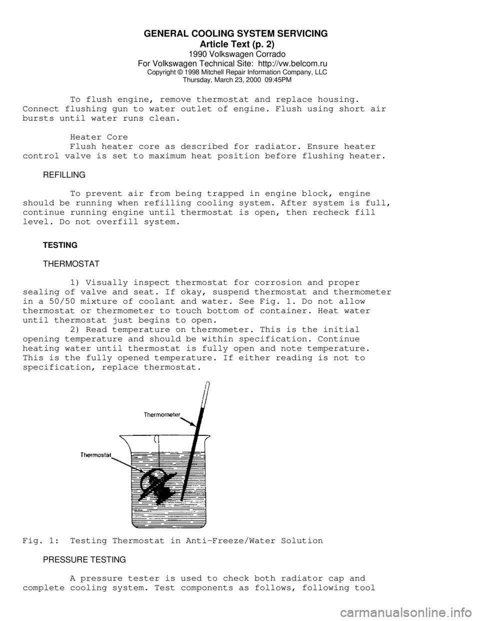
1) Visually inspect thermostat for corrosion and proper
sealing of valve and seat. If okay, suspend thermostat and thermometer
in a 50/50 mixture of coolant and water. See Fig. 1. Do not allow
thermostat or thermometer to touch bottom of container. Heat water
until thermostat just begins to open.
2) Read temperature on thermometer. This is the initial
opening temperature and should be within specification. Continue
heating water until thermostat is fully open and note temperature.
This is the fully opened temperature. If either reading is not to
specification, replace thermostat.Fig. 1: Testing Thermostat in Anti-Freeze/Water Solution
PRESSURE TESTING
A pressure tester is used to check both radiator cap and
complete cooling system. Test components as follows, following tool
Page 578 of 906

H - TESTS W/O CODES
Article Text (p. 5)
1990 Volkswagen Corrado
For Volkswagen Technical Site: http://vw.belcom.ru
Copyright © 1998 Mitchell Repair Information Company, LLC
Thursday, March 23, 2000 09:45PM
* Ensure there are no vacuum leaks.
* Check idle stabilizer operation (if equipped).
* Ensure fuel system pressure and volume are correct.
* Check auxiliary air by-pass regulator.
* Check cold start valve for leaking (engine warm).
ENGINE HESITATES ON ACCELERATION
* Inspect intake air components for leaking hoses
* Check injector spray pattern. Check for faulty injectors.
* Check cold start valve for leaking (engine warm).
* Check airflow sensor plate movement. Replace fuel distributor
as necessary.
* Check airflow sensor plate position. Adjust as necessary.
* Check fuel system and control system pressure. Replace pressure
regulator if necessary.
* Test airflow sensor plate potentiometer. Adjust or replace
as necessary.
* Perform system electrical checks.
* Check idle mixture CO adjustment. Adjust as necessary.
ENGINE LACKS POWER
* Test coolant temperature sensor and wiring. Repair or
replace as required.
* Check fuel system and control system pressure. Replace pressure
regulator if necessary.
* Check throttle cable adjustment.
* Check throttle switch. Adjust or replace as necessary.
* Check airflow sensor screen for damage or incorrect installation
(if equipped).
* Check ignition timing and knock sensor control (if equipped).
Adjust as necessary.
* Check EGR system for correct operation (if equipped).
* Ensure base timing is correct and timing advance system
is functional.
* Check transmission for correct downshift (auto. trans.)
* Check fuel tank filler tube for tampering of restrictor. If
tampering has occurred, check catalytic converter for lead
contamination and exhaust system restriction.
* Check for use of poor quality fuel containing insufficient
cleaning additives. Prolonged use of poor quality fuel can
cause injector clogging and carbon build-up on intake system.
* Inspect intake air element, housing, and preheating system.
* Check airflow sensor plate movement. Replace if necessary.
POOR FUEL MILEAGE
* Ensure idle speed, base timing and timing advance are
set to specifications.
* Check cold start valve for leaking (engine warm).
Page 579 of 906

H - TESTS W/O CODES
Article Text (p. 6)
1990 Volkswagen Corrado
For Volkswagen Technical Site: http://vw.belcom.ru
Copyright © 1998 Mitchell Repair Information Company, LLC
Thursday, March 23, 2000 09:45PM
* Check fuel system and control system pressure. Replace
pressure regulator if necessary.
* Check thermo time switch operation.
* Check airflow sensor voltage output.
* Check air induction system for leaks.
* Check fuel injector operation.
* Check coolant temperature sensor operation.
* Check Oxygen (O2) sensor operation.
ENGINE DIESELING
CIS-E & CIS-E MOTRONIC
* Ensure ignition timing and timing advance are set to
specifications.
* Check for engine overheating.
* Check cold start valve for leaking (engine warm).
* Check for leaking injectors.
* Check airflow sensor plate/control plunger rest position.
Adjust as necessary.
* Check carbon canister solenoid valve.
* Verify no leaks in exhaust system.
FAILED EMISSIONS TEST
* Test lambda control system. Replace if faulty.
* Check air/fuel mixture. Adjust if necessary.
* Ensure air intake system is not restricted.
* Ensure engine is at normal operating temperature.
* Ensure fuel system pressure is correct.
* Check cold start valve for leaking (engine warm).
* Check thermo time switch operation.
* Verify base timing is correct.
* Check for correct PCV valve operation.
* Check crankcase for gasoline contamination.
* Check idle stabilizer operation.
* Check EGR system for correct operation (if equipped).
* Check vapor recovery system operation.
* Check operation of coolant temperature sensor.
* Check fuel tank filler tube for tampering of restrictor.
If tampering has occurred, check catalytic converter for
lead contamination and exhaust system restriction.
* Check for use of poor quality fuel containing insufficient
cleaning additives. Prolonged use of poor quality fuel can
cause injector clogging and carbon build-up on intake system.
INTERMITTENT PROBLEM DIAGNOSIS
Intermittent fault testing requires duplicating circuit or
component failure to identify the problem. If necessary, monitor
voltage or resistance values using a DVOM while attempting to
Page 588 of 906

I - SYSTEM/COMPONENT TESTS
Article Text
1990 Volkswagen Corrado
For Volkswagen Technical Site: http://vw.belcom.ru
Copyright © 1998 Mitchell Repair Information Company, LLC
Thursday, March 23, 2000 09:46PM
ARTICLE BEGINNING
1990 ENGINE PERFORMANCE
Systems & Component Testing
Volkswagen; Cabriolet, Corrado, Fox, Golf GL/GTI,
Jetta, Vanagon
INTRODUCTION
Before testing separate components or systems, perform
procedures in F - BASIC TESTING and H - TESTS W/O CODES articles.
NOTE: Testing individual components does not isolate shorts or
opens. Perform all voltage tests with a Digital
Volt-Ohmmeter (DVOM) with a minimum 10-megohm input
impedance, unless stated otherwise in test procedure. Use
ohmmeter to isolate wiring harness shorts or opens.
AIR INDUCTION SYSTEMS (SUPERCHARGER)
BOOST PRESSURE
1) Before checking supercharger boost pressure, ensure engine
idle speed is correct. See D - ADJUSTMENTS article. Ensure engine oil
temperature is 176øF (80øC). Check knock sensor operation. See KNOCK
SENSOR under IDLE CONTROL SYSTEM in this article.
2) Connect Pressure Gauge (VW1397) or equivalent to the
pressure regulator hose using adapter "T". Open pressure gauge check
valve to position "A" and start engine.
3) Remove harness connector from CO potentiometer and Blue
connector from temperature sensor (in front flange on cylinder head).
Accelerate to full throttle. Engine speed must increase periodically
then drop (surge). Watch pressure gauge, boost pressure must reach 8.7
psi (0.6 kg/cm
ý). If boost does not reach specification, check for
leaks in air system and correct by-pass valve setting. Check
supercharger.
COMPUTERIZED ENGINE CONTROLS
NOTE: For fuel system used on model being tested, see FUEL SYSTEM
APPLICATION table.
FUEL SYSTEM APPLICATION
ÄÄÄÄÄÄÄÄÄÄÄÄÄÄÄÄÄÄÄÄÄÄÄÄÄÄÄÄÄÄÄÄÄÄÄÄÄÄÄÄÄÄÄÄÄÄÄÄÄÄÄÄÄÄÄÄÄÄÄÄÄÄÄÄÄÄÄÄÄÄApplication Fuel System
Cabriolet, Corrado, Golf GL/GTI,
Jetta & Vanagon .................................. AFC-Digifant II
Fox .......................................................... CIS-E
Jetta GLi ............................................. CIS-Motronic
Page 592 of 906
I - SYSTEM/COMPONENT TESTS
Article Text (p. 5)
1990 Volkswagen Corrado
For Volkswagen Technical Site: http://vw.belcom.ru
Copyright © 1998 Mitchell Repair Information Company, LLC
Thursday, March 23, 2000 09:46PM
COOLANT TEMPERATURE SENSOR
Turn ignition off. Use a thermometer to measure coolant
temperature. Unplug connector from Electronic Control Unit (ECU).
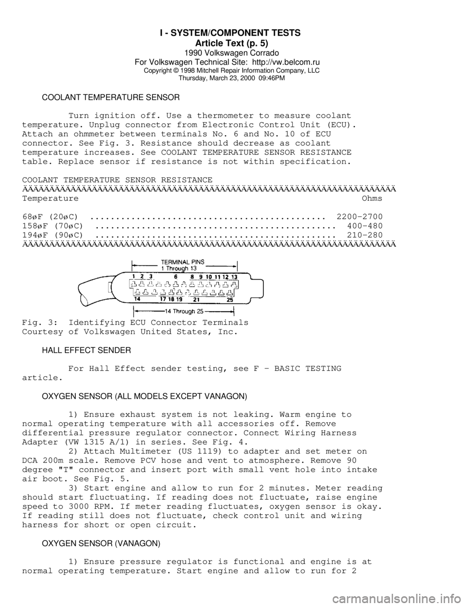
Attach an ohmmeter between terminals No. 6 and No. 10 of ECU
connector. See Fig. 3. Resistance should decrease as coolant
temperature increases. See COOLANT TEMPERATURE SENSOR RESISTANCE
table. Replace sensor if resistance is not within specification.
COOLANT TEMPERATURE SENSOR RESISTANCEÄÄÄÄÄÄÄÄÄÄÄÄÄÄÄÄÄÄÄÄÄÄÄÄÄÄÄÄÄÄÄÄÄÄÄÄÄÄÄÄÄÄÄÄÄÄÄÄÄÄÄÄÄÄÄÄÄÄÄÄÄÄÄÄÄÄÄÄÄÄTemperature Ohms
68
øF (20øC) .............................................. 2200-2700
158
øF (70øC) ............................................... 400-480
194
øF (90øC) ............................................... 210-280
ÄÄÄÄÄÄÄÄÄÄÄÄÄÄÄÄÄÄÄÄÄÄÄÄÄÄÄÄÄÄÄÄÄÄÄÄÄÄÄÄÄÄÄÄÄÄÄÄÄÄÄÄÄÄÄÄÄÄÄÄÄÄÄÄÄÄÄÄÄÄFig. 3: Identifying ECU Connector Terminals
Courtesy of Volkswagen United States, Inc.
HALL EFFECT SENDER
For Hall Effect sender testing, see F - BASIC TESTING
article.
OXYGEN SENSOR (ALL MODELS EXCEPT VANAGON)
1) Ensure exhaust system is not leaking. Warm engine to
normal operating temperature with all accessories off. Remove
differential pressure regulator connector. Connect Wiring Harness
Adapter (VW 1315 A/1) in series. See Fig. 4.
2) Attach Multimeter (US 1119) to adapter and set meter on
DCA 200m scale. Remove PCV hose and vent to atmosphere. Remove 90
degree "T" connector and insert port with small vent hole into intake
air boot. See Fig. 5.
3) Start engine and allow to run for 2 minutes. Meter reading
should start fluctuating. If reading does not fluctuate, raise engine
speed to 3000 RPM. If meter reading fluctuates, oxygen sensor is okay.
If reading still does not fluctuate, check control unit and wiring
harness for short or open circuit.
OXYGEN SENSOR (VANAGON)
1) Ensure pressure regulator is functional and engine is at
normal operating temperature. Start engine and allow to run for 2
Page 594 of 906
I - SYSTEM/COMPONENT TESTS
Article Text (p. 7)
1990 Volkswagen Corrado
For Volkswagen Technical Site: http://vw.belcom.ru
Copyright © 1998 Mitchell Repair Information Company, LLC
Thursday, March 23, 2000 09:46PM
1) Disconnect throttle valve switch connector. With ohmmeter
set on 200-ohm scale, attach probes to male terminals. Ensure throttle
valve switch is completely closed. With throttle valve closed, meter
reading should be zero.
2) Position throttle valve to 1/2 open position. Ohmmeter
reading should be infinite. Position throttle to fully open position.
Ohmmeter reading should be zero. If any reading is incorrect, perform
throttle valve switch adjustment. See D - ADJUSTMENTS article.
3) If correct specifications cannot be obtained, check
throttle shaft play, accelerator cable adjustment and throttle switch
actuating cam. If okay, replace throttle valve switch.
RELAYS
FUEL PUMP RELAY (CABRIOLET, GOLF GL/GTI & JETTA)
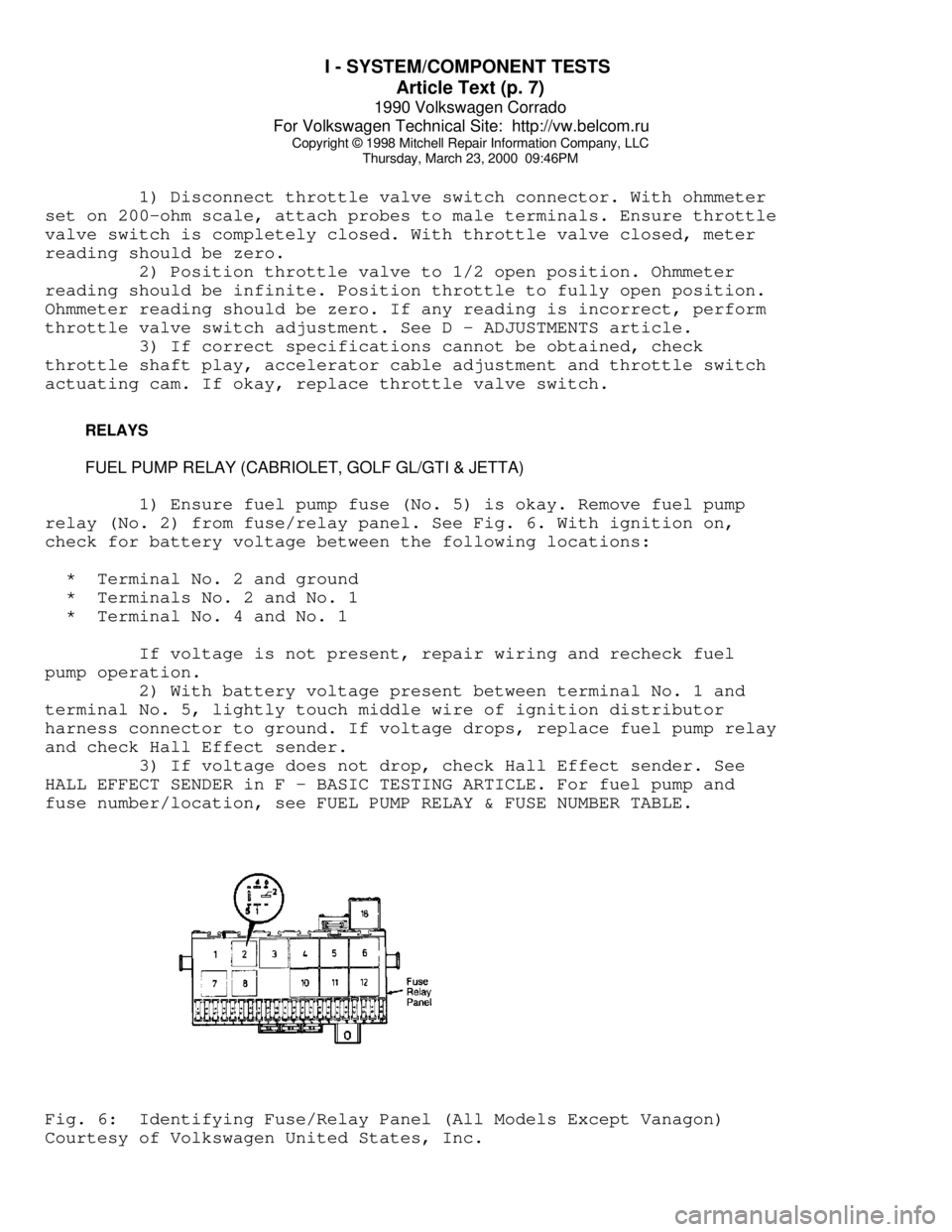
1) Ensure fuel pump fuse (No. 5) is okay. Remove fuel pump
relay (No. 2) from fuse/relay panel. See Fig. 6. With ignition on,
check for battery voltage between the following locations:
* Terminal No. 2 and ground
* Terminals No. 2 and No. 1
* Terminal No. 4 and No. 1
If voltage is not present, repair wiring and recheck fuel
pump operation.
2) With battery voltage present between terminal No. 1 and
terminal No. 5, lightly touch middle wire of ignition distributor
harness connector to ground. If voltage drops, replace fuel pump relay
and check Hall Effect sender.
3) If voltage does not drop, check Hall Effect sender. See
HALL EFFECT SENDER in F - BASIC TESTING ARTICLE. For fuel pump and
fuse number/location, see FUEL PUMP RELAY & FUSE NUMBER TABLE.Fig. 6: Identifying Fuse/Relay Panel (All Models Except Vanagon)
Courtesy of Volkswagen United States, Inc.