1990 VOLKSWAGEN CORRADO set
[x] Cancel search: setPage 325 of 906

A/C COMPRESSOR OIL CHECKING
Article Text (p. 7)
1990 Volkswagen Corrado
For Volkswagen Technical Site: http://vw.belcom.ru
Copyright © 1998 Mitchell Repair Information Company, LLC
Thursday, March 23, 2000 09:41PM
compressor, receiver-drier and expansion valve. Clean expansion valve
screen. Flush entire system. Install new compressor and receiver-
drier. New compressors contain correct amount of oil. If installing
overhauled compressor, add 1.5 ounces of new refrigerant oil through
suction port.
PANASONIC ROTARY VANE DRAIN & REFILL
1) Before checking and adjusting oil level, operate
compressor at 1000-1500 engine RPM, and set controls at maximum
cooling and high blowing speed for about 10 minutes to return oil to
compressor.
2) Stop engine. Discharge refrigerant and remove compressor
from vehicle. See SERVICING PRECAUTIONS at the beginning of this
article. Drain oil from compressor through suction and discharge
ports. Measure amount of oil drained. If amount drained is more than
2.4 ounces, fill with same amount using new oil. If amount drained is
less than 2.4 ounces, fill with 2.4 ounces. Install compressor and
recharge.
3) If A/C components are replaced, add refrigerant oil to
system. Add 1.4 ounces if condenser is replaced. Add 2 ounces if the
evaporator is replaced. Oil does not need to be added if receiver-
drier is replaced.
SANDEN SCROLL DRAIN & REFILL
Discharge system. Remove compressor from vehicle. Drain oil
from compressor through inlet and outlet holes. Refill compressor with
2.8 ounces of oil through suction port. When replacing condenser, add
.5 ounce. When replacing evaporator, add 1.7 ounces. When replacing
other A/C components, add .5 ounce per component replaced.
SANDEN 5-CYL DRAIN & REFILL
1) Discharge system. Remove compressor belt and loosen
mounting bolts. Rotate compressor in brackets until filler plug is at
top. Clean area around filler plug and remove plug slowly. Rotate
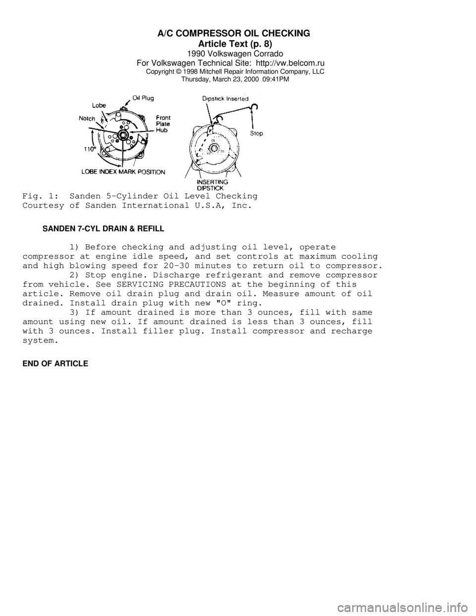
front hub plate so notch in lobe is 110 degrees from the bottom. This
rotates ball end of top piston to align with oil fill port and allows
clearance for dipstick. See Fig. 1.
2) Insert compressor dipstick diagonally from right to left
until stop on dipstick contacts filler plug surface. Remove dipstick
and note oil fill level. Each increment on dipstick represents one
ounce of oil. Add oil if necessary to reach 3-4 ounce level.
Page 326 of 906
A/C COMPRESSOR OIL CHECKING
Article Text (p. 8)
1990 Volkswagen Corrado
For Volkswagen Technical Site: http://vw.belcom.ru
Copyright © 1998 Mitchell Repair Information Company, LLC
Thursday, March 23, 2000 09:41PMFig. 1: Sanden 5-Cylinder Oil Level Checking
Courtesy of Sanden International U.S.A, Inc.
SANDEN 7-CYL DRAIN & REFILL
1) Before checking and adjusting oil level, operate
compressor at engine idle speed, and set controls at maximum cooling
and high blowing speed for 20-30 minutes to return oil to compressor.
2) Stop engine. Discharge refrigerant and remove compressor
from vehicle. See SERVICING PRECAUTIONS at the beginning of this
article. Remove oil drain plug and drain oil. Measure amount of oil
drained. Install drain plug with new "O" ring.
3) If amount drained is more than 3 ounces, fill with same
amount using new oil. If amount drained is less than 3 ounces, fill
with 3 ounces. Install filler plug. Install compressor and recharge
system.
END OF ARTICLE
Page 327 of 906

A/C COMPRESSOR SERVICING
Article Text
1990 Volkswagen Corrado
For Volkswagen Technical Site: http://vw.belcom.ru
Copyright © 1998 Mitchell Repair Information Company, LLC
Thursday, March 23, 2000 09:41PM
ARTICLE BEGINNING
1990 AIR CONDITIONING & HEAT
Compressor Service
* PLEASE READ THIS FIRST *
CAUTION: When discharging air conditioning system, use only approved
refrigerant recovery/recycling equipment. Make every attempt
to avoid discharging refrigerant into the atmosphere.
ISOLATING COMPRESSOR
NOTE: Only compressors with stem-type service valves can be
isolated.
1) Connect service gauge set to the compressor service valves
and open compressor valves slightly (turn in clockwise). Start engine
and operate air conditioning. Slowly turn compressor suction valve
clockwise toward closed (front-seated) position.
2) When suction pressure is reduced to zero or less, turn off
engine and compressor and quickly turn suction valve stem in to full
front-seated position. Suction pressure should be slightly above zero.
Turn discharge valve into front-seated position.
3) To check oil level, slowly open compressor crankcase plug
to relieve any remaining pressure. After oil level is corrected, cap
service gauge ports on both valves. Back-seat suction service valve to
allow refrigerant to enter compressor. Open discharge valve halfway.
4) Loosen discharge service valve cap, allowing refrigerant
pressure to force air out of compressor. Back-seat service valve and
tighten cap. Compressor is now ready for operation.
REFRIGERANT OIL
Only new, pure, moisture-free refrigerant oil should be used
in the air conditioning system. This oil is highly refined and
dehydrated to a point where moisture content is less than 10 parts per
million. The oil container must be tightly closed at all times when
not in use, or moisture will be absorbed into the refrigerant oil from
the air.
DISCHARGING SYSTEM PRECAUTIONS
CAUTION: When discharging air conditioning system, use only approved
refrigerant recovery/recycling equipment. Make every attempt
to avoid discharging refrigerant into the atmosphere.
If compressor has stem-type service valves, it can be
isolated and removed without discharging entire system. Otherwise,
discharge system completely using approved refrigerant
Page 339 of 906
A/C COMPRESSOR SERVICING
Article Text (p. 13)
1990 Volkswagen Corrado
For Volkswagen Technical Site: http://vw.belcom.ru
Copyright © 1998 Mitchell Repair Information Company, LLC
Thursday, March 23, 2000 09:41PM
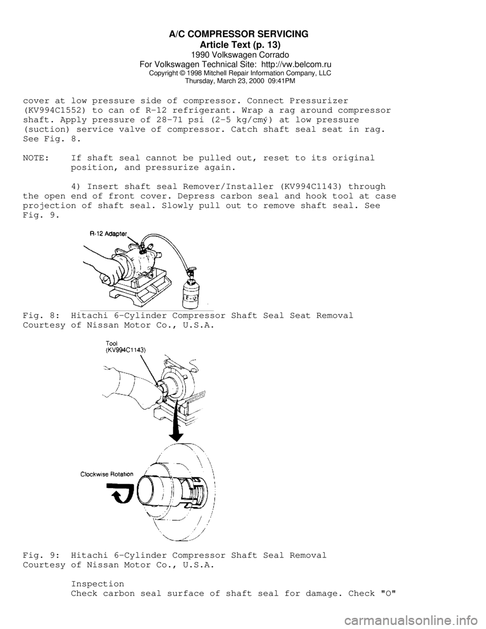
cover at low pressure side of compressor. Connect Pressurizer
(KV994C1552) to can of R-12 refrigerant. Wrap a rag around compressor
shaft. Apply pressure of 28-71 psi (2-5 kg/cmý) at low pressure
(suction) service valve of compressor. Catch shaft seal seat in rag.
See Fig. 8.
NOTE: If shaft seal cannot be pulled out, reset to its original
position, and pressurize again.
4) Insert shaft seal Remover/Installer (KV994C1143) through
the open end of front cover. Depress carbon seal and hook tool at case
projection of shaft seal. Slowly pull out to remove shaft seal. See
Fig. 9.Fig. 8: Hitachi 6-Cylinder Compressor Shaft Seal Seat Removal
Courtesy of Nissan Motor Co., U.S.A.Fig. 9: Hitachi 6-Cylinder Compressor Shaft Seal Removal
Courtesy of Nissan Motor Co., U.S.A.
Inspection
Check carbon seal surface of shaft seal for damage. Check "O"
Page 350 of 906

A/C SYSTEM GENERAL DIAGNOSTIC PROCEDURES
Article Text (p. 2)
1990 Volkswagen Corrado
For Volkswagen Technical Site: http://vw.belcom.ru
Copyright © 1998 Mitchell Repair Information Company, LLC
Thursday, March 23, 2000 09:41PM
5000 ........................ 24.92 ......................... +5.0
6000 ........................ 23.92 ......................... +6.0
7000 ........................ 23.02 ......................... +6.9
8000 ........................ 22.22 ......................... +7.7
9000 ........................ 21.32 ......................... +8.6
10,000 ...................... 20.52 ......................... +9.4
(1) - Add correction shown to gauge readings.ÄÄÄÄÄÄÄÄÄÄÄÄÄÄÄÄÄÄÄÄÄÄÄÄÄÄÄÄÄÄÄÄÄÄÄÄÄÄÄÄÄÄÄÄÄÄÄÄÄÄÄÄÄÄÄÄÄÄÄÄÄÄÄÄÄÄÄÄÄÄ PREPARATION FOR TESTING
1) Attach Low and High pressure gauges.
2) Start engine and allow to warm up.
3) Set system to "COOL" and blower to "HIGH".
4) Open car doors and hood.
5) Run engine at fast idle for 2-3 minutes.
AIR CONDITIONING SYSTEM PERFORMANCE CHECK TABLE
ÄÄÄÄÄÄÄÄÄÄÄÄÄÄÄÄÄÄÄÄÄÄÄÄÄÄÄÄÄÄÄÄÄÄÄÄÄÄÄÄÄÄÄÄÄÄÄÄÄÄÄÄÄÄÄÄÄÄÄÄÄÄÄÄÄÄÄÄÄPERFORM TESTS: SHOULD BE: IF:
ÄÄÄÄÄÄÄÄÄÄÄÄÄÄÄÄÄÄÄÄÄÄÄÄÄÄÄÄÄÄÄÄÄÄÄÄÄÄÄÄÄÄÄÄÄÄÄÄÄÄÄÄÄÄÄÄÄÄÄÄÄÄÄÄÄÄÄÄÄTemperature Check Temperature Check Is
* Switch to "LOW" blower.
* Close doors.
* Check outlet temperature. 35-45
ø F Too warm - Check control
lever operation, heater
water valve, cooling
system and gauge
readings.
ÄÄÄÄÄÄÄÄÄÄÄÄÄÄÄÄÄÄÄÄÄÄÄÄÄÄÄÄÄÄÄÄÄÄÄÄÄÄÄÄÄÄÄÄÄÄÄÄÄÄÄÄÄÄÄÄÄÄÄÄÄÄÄÄÄÄÄÄÄÄVisual Check Visual Check Shows:
* Compressor Quiet, No Leaks Noisy - Check belts, oil
level, seals, gaskets,
reed valves.
* Condenser Free of Obstructions Blocked - Clean off.
Plugged - Flush or
replace.
* Receiver-Drier Dry & warm to touch Frosty - Check for
restriction, replace
desiccant.
* Sight Glass Clear or few bubbles Bubbly, foamy or streaks
- Check gauge readings.
* High Side Lines Dry & warm to touch Frosty or very hot -
Check for restriction or
overcharge.
* Low Side Lines Dry & cool to touch Frosty or warm - Check
for restriction, low
charge or bad valve.
* Expansion Valve Dry Frosty - Check for
Page 356 of 906

A/C SYSTEM PRECAUTIONS
Article Text (p. 3)
1990 Volkswagen Corrado
For Volkswagen Technical Site: http://vw.belcom.ru
Copyright © 1998 Mitchell Repair Information Company, LLC
Thursday, March 23, 2000 09:41PM
refrigerant into the system.
On 2-piece can taps, be certain tap handle is turned fully
inward to the closed position. Check that locking base is turned to
its outer limit. Securely engage locking lugs over the can flange.
Turn entire tap assembly (without disturbing the closed setting)
downward into the locking base to pierce the can. DO NOT open tap
until ready to dispense into system.
SCREW TYPE SEAL CANS
Ensure can tap is fully closed. Screw refrigerant can into
can tap fitting until tight. This will pierce the can. Connect tap to
center hose on manifold gauge set. DO NOT open tap until ready to
dispense R-12 into system.
WARNING: DO NOT open high side hand valve while air conditioning
system is in operation. This high pressure could rupture can
or fitting at safety can valve, resulting in damage and
personal injury.
CONNECTING LINES & FITTINGS
A new "O" ring should be used in all instances when
connecting lines and fittings (dip "O" ring in clean refrigeration oil
and make certain it is not twisted during installation). Always use
two wrenches to avoid twisting or distorting lines and fittings,
tighten coupling nuts securely.
PLACING SYSTEM IN OPERATION
After component replacement and/or system servicing has been
completed and all connections have been made, proceed as follows:
1) Evacuate the system using a vacuum pump.
2) Charge the system with new R-12 (refrigerant) according to
each individual vehicle as outlined in the GENERAL SERVICING article.
Also see Refrigerant Capacity in this Section.
3) Leak test the system, with particular attention to all new
connections and components.
4) Make a performance test of the system. Never assume that a
recharging has automatically corrected a problem.
COMPRESSOR REMOVAL INFORMATION - ISOLATION METHOD
On systems which have compressors equipped with stem-type
service valves (Tecumseh), it is possible to isolate the compressor
for removal.
Isolating
Turn both high and low pressure manual valves to extreme
clockwise (front seat) position. Loosen cap on high pressure manual
Page 359 of 906
A/C-HEATER SYSTEM - MANUAL
Article Text (p. 2)
1990 Volkswagen Corrado
For Volkswagen Technical Site: http://vw.belcom.ru
Copyright © 1998 Mitchell Repair Information Company, LLC
Thursday, March 23, 2000 09:41PM
Temperature Control Lever
The temperature control lever controls heating and cooling.
When moved to the left, lever turns compressor on. When moved to the
right, a heater water valve is opened, supplying coolant to heater
core.
HIGH-PRESSURE SWITCH
High-pressure switch shuts compressor off if high pressure
reaches 210 psi (14.8 kg/cmý). High-pressure switch will reset when
pressure decreases to 174 psi (12.2 kg/cm
ý).
LOW-PRESSURE SWITCH
Low-pressure switch cuts off system operation when there is
abnormally low pressure in system. This protects the compressor when
there is not enough R-12 in system. Low-pressure switch shuts
compressor off at 26 psi (1.8 kg/cm
ý).
THERMOSWITCH
Thermoswitch shuts compressor off if coolant temperature
rises above 248
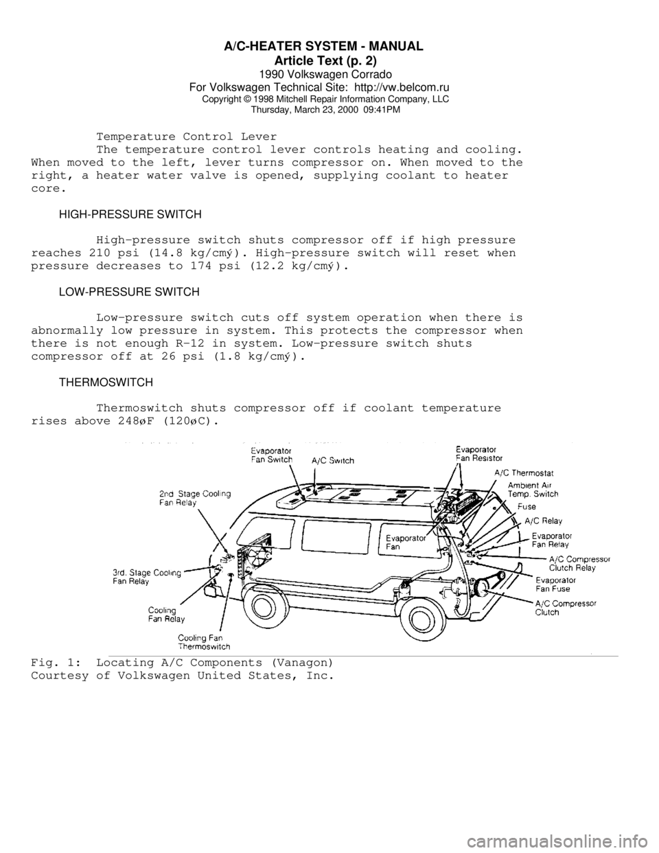
øF (120øC).Fig. 1: Locating A/C Components (Vanagon)
Courtesy of Volkswagen United States, Inc.
Page 362 of 906

A/C-HEATER SYSTEM - MANUAL
Article Text (p. 5)
1990 Volkswagen Corrado
For Volkswagen Technical Site: http://vw.belcom.ru
Copyright © 1998 Mitchell Repair Information Company, LLC
Thursday, March 23, 2000 09:41PM
MICROSWITCH
Loosen microswitch mounting screw. Move microswitch so switch
is on when lever is at maximum A/C, NORM (normal), BI-LEVEL or extreme
right position, and off when lever is at VENT or HEAT position.
Tighten microswitch mounting screw. Recheck operation.
TEMPERATURE SWITCH
Move temperature lever to full cool position. Loosen
temperature switch mounting screw. Move temperature switch
counterclockwise to full stop position. Tighten temperature switch
mounting screw.
TROUBLE SHOOTING
NO COOLING
1) Ensure fan motor operates in all 4 speeds, air duct closes
off outside air and heater water valve is closed. Adjust belt tension.
2) Inspect receiver-drier pressure seal. If seal is good, go
to step 5). If seal is broken, evacuate and recharge system. If system
cools properly, testing is complete. If system does not cool, connect
pressure gauges.
3) Set engine speed at 2500 RPM. Insert thermometer in left
register and close all others. Place controls on high blower and
maximum cooling. With vehicle out of direct sunlight, close all
windows. Radiator fan should come on with system pressure at 200 psi
(14 kg/cmý).
NOTE: If system doors allow air leaks, evaporator will freeze up
and testing will not be possible.
4) If fan does not operate, replace pressure switch. Ensure
system is okay. If fan does come on, turn engine off and check for
condenser obstructions and blocked airflow.
5) Turn air conditioner on and off with temperature control
lever. Ensure compressor clutch engages. Push lever to extreme right
position and back again. A click should be heard from compressor
clutch. If a click is not heard, check for voltage at clutch coil wire
with switch on. If voltage is present, replace clutch coil. If voltage
is not present, check wiring or replace thermostatic switch.
6) If compressor clutch operates, check gauge readings. If
both are low, locate leak and recharge system. If both are high,
replace expansion valve. If low side is too high and high side reads
too low, replace or rebuild compressor.
INSUFFICIENT COOLING
1) Ensure fan motor operates at all 4 speeds, air duct closes
off outside air intake and heater water valve is closed. Adjust
compressor belt tension and clean condenser.