1990 VOLKSWAGEN CORRADO ground clearance
[x] Cancel search: ground clearancePage 445 of 906
D - ADJUSTMENTS
Article Text (p. 8)
1990 Volkswagen Corrado
For Volkswagen Technical Site: http://vw.belcom.ru
Copyright © 1998 Mitchell Repair Information Company, LLC
Thursday, March 23, 2000 09:43PM
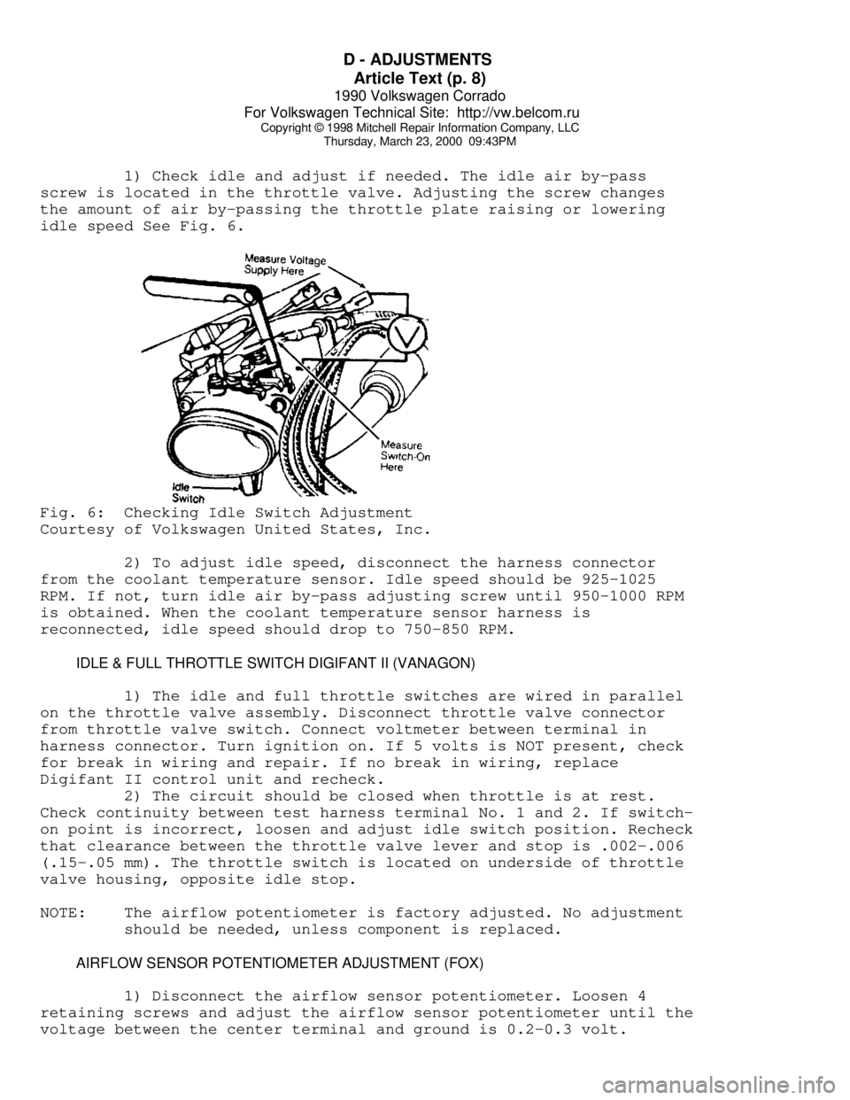
1) Check idle and adjust if needed. The idle air by-pass
screw is located in the throttle valve. Adjusting the screw changes
the amount of air by-passing the throttle plate raising or lowering
idle speed See Fig. 6.Fig. 6: Checking Idle Switch Adjustment
Courtesy of Volkswagen United States, Inc.
2) To adjust idle speed, disconnect the harness connector
from the coolant temperature sensor. Idle speed should be 925-1025
RPM. If not, turn idle air by-pass adjusting screw until 950-1000 RPM
is obtained. When the coolant temperature sensor harness is
reconnected, idle speed should drop to 750-850 RPM.
IDLE & FULL THROTTLE SWITCH DIGIFANT II (VANAGON)
1) The idle and full throttle switches are wired in parallel
on the throttle valve assembly. Disconnect throttle valve connector
from throttle valve switch. Connect voltmeter between terminal in
harness connector. Turn ignition on. If 5 volts is NOT present, check
for break in wiring and repair. If no break in wiring, replace
Digifant II control unit and recheck.
2) The circuit should be closed when throttle is at rest.
Check continuity between test harness terminal No. 1 and 2. If switch-
on point is incorrect, loosen and adjust idle switch position. Recheck
that clearance between the throttle valve lever and stop is .002-.006
(.15-.05 mm). The throttle switch is located on underside of throttle
valve housing, opposite idle stop.
NOTE: The airflow potentiometer is factory adjusted. No adjustment
should be needed, unless component is replaced.
AIRFLOW SENSOR POTENTIOMETER ADJUSTMENT (FOX)
1) Disconnect the airflow sensor potentiometer. Loosen 4
retaining screws and adjust the airflow sensor potentiometer until the
voltage between the center terminal and ground is 0.2-0.3 volt.
Page 519 of 906
ENGINE OVERHAUL PROCEDURES - GENERAL INFORMATION
Article Text (p. 10)
1990 Volkswagen Corrado
For Volkswagen Technical Site: http://vw.belcom.ru
Copyright © 1998 Mitchell Repair Information Company, LLC
Thursday, March 23, 2000 09:44PM
Replacing Valve Guide
Replace valve guide if clearance exceeds specification. Valve
guides are either pressed, hammered or shrunk in place, depending upon
cylinder head design and type of metal used.
Remove valve guide from cylinder head by pressing or tapping
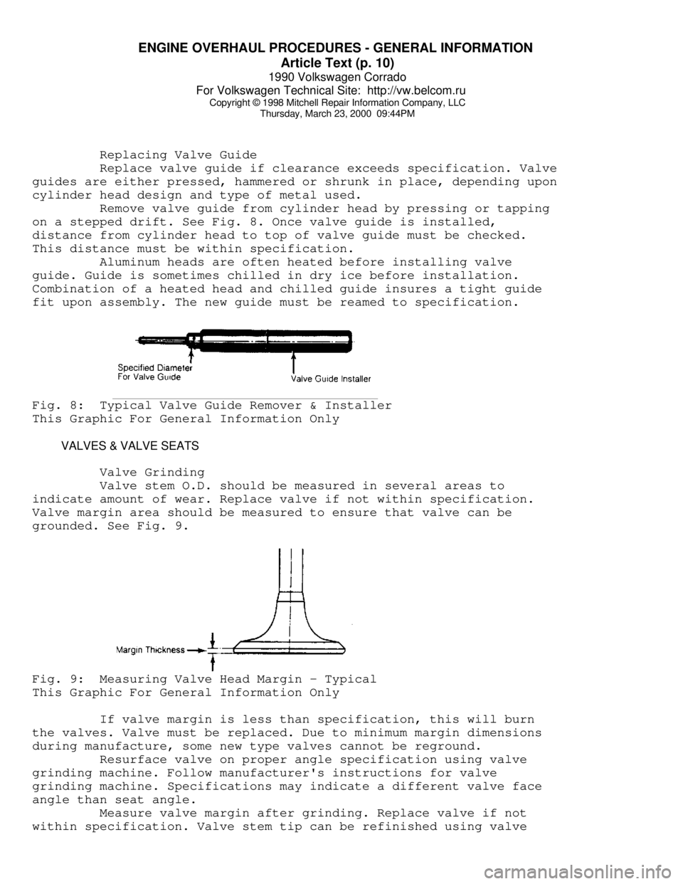
on a stepped drift. See Fig. 8. Once valve guide is installed,
distance from cylinder head to top of valve guide must be checked.
This distance must be within specification.
Aluminum heads are often heated before installing valve
guide. Guide is sometimes chilled in dry ice before installation.
Combination of a heated head and chilled guide insures a tight guide
fit upon assembly. The new guide must be reamed to specification.Fig. 8: Typical Valve Guide Remover & Installer
This Graphic For General Information Only
VALVES & VALVE SEATS
Valve Grinding
Valve stem O.D. should be measured in several areas to
indicate amount of wear. Replace valve if not within specification.
Valve margin area should be measured to ensure that valve can be
grounded. See Fig. 9.Fig. 9: Measuring Valve Head Margin - Typical
This Graphic For General Information Only
If valve margin is less than specification, this will burn
the valves. Valve must be replaced. Due to minimum margin dimensions
during manufacture, some new type valves cannot be reground.
Resurface valve on proper angle specification using valve
grinding machine. Follow manufacturer's instructions for valve
grinding machine. Specifications may indicate a different valve face
angle than seat angle.
Measure valve margin after grinding. Replace valve if not
within specification. Valve stem tip can be refinished using valve
Page 523 of 906

ENGINE OVERHAUL PROCEDURES - GENERAL INFORMATION
Article Text (p. 14)
1990 Volkswagen Corrado
For Volkswagen Technical Site: http://vw.belcom.ru
Copyright © 1998 Mitchell Repair Information Company, LLC
Thursday, March 23, 2000 09:44PM
ROCKER ARMS & ASSEMBLIES
Rocker Studs
Rocker studs are either threaded or pressed in place.
Threaded studs are removed by locking 2 nuts on the stud. Unscrew the
stud by turning the jam nut. Coat the stud threads with Loctite and
install. Tighten to specification.
Pressed in stud can be removed using a stud puller. Ream the
stud bore to proper specification and press in a new oversize stud.
Pressed in studs are often replaced by cutting threads in the stud
bore to accept a threaded stud.
Rocker Arms & Shafts
Mark rocker arms for location. Remove rocker arm retaining
bolts. Remove rocker arms. Inspect rocker arms, shafts, bushings and
pivot balls (if equipped) for excessive wear. Inspect rocker arms
for wear in valve stem contact area. Measure rocker arm bushing I.D.
Replace bushings if excessively worn.
The rocker arm valve stem contact point can be reground,
using special fixture for valve grinding machine. Remove minimum
amount of material as possible. Ensure all oil passages are clear.
Install rocker arms in original locations. Ensure rocker arm is
properly seated in push rod. Tighten bolts to specification. Adjust
valves if required. See VALVE ADJUSTMENT in this article.
Pushrods
Remove rocker arms. Mark push rods for location. Remove push
rods. Push rods can be steel or aluminum, solid or hollow. Hollow
pushrods must be internally cleaned to ensure oil passage to the
rocker arms is cleaned. Check the pushrod for damage, such as loose
ends on steel tipped aluminum types.
Check push rod for straightness. Roll push rod on a flat
surface. Using feeler gauge, check clearance at center. Replace push
rod if bent. The push rod can also be supported at each end and
rotated. A dial indicator is used to detect bends in the push rod.
Lubricate ends of push rod and install push rod in original
location. Ensure push rod is properly seated in lifter. Install rocker
arm. Tighten bolts to specification. Adjust valves if required. See
VALVE ADJUSTMENT in this article.
LIFTERS
Hydraulic Lifters
Before replacing a hydraulic lifter for noisy operation,
ensure noise is not caused by worn rocker arms or valve tips.
Hydraulic lifter assemblies must be installed in original locations.
Remove the rocker arm assembly and push rod. Mark components for
location. Some applications require intake manifold, or lifter cover
removal. Remove lifter retainer plate (if used). To remove lifters,
use a hydraulic lifter remover or magnet. Different type lifters are
used. See Fig. 13.
Page 764 of 906

TRANSMISSION REMOVAL & INSTALLATION - A/T
Article Text
1990 Volkswagen Corrado
For Volkswagen Technical Site: http://vw.belcom.ru
Copyright © 1998 Mitchell Repair Information Company, LLC
Thursday, March 23, 2000 09:51PM
ARTICLE BEGINNING
1990-91 TRANSMISSION SERVICING
Automatic Transmission Removal & Installation
Cabriolet, Corrado, Fox, Golf GTI, Jetta, Passat
CABRIOLET, GOLF, GTI & JETTA
NOTE: For manual transaxle replacement procedures, see appropriate
CLUTCH article in the CLUTCHES Section.
REMOVAL & INSTALLATION
1) Disconnect battery ground cable. Disconnect speedometer
cable from transaxle. Raise and support vehicle. Remove left front
wheel.
2) Support engine from above. Remove left rear transaxle
mount and support. Remove upper transaxle-to-engine bolts. Remove
upper bolts from front engine/transaxle mount.
3) Remove lower bolts on front mount and remove mount. Remove
protective plate from transaxle. Remove torque converter-to-drive
plate bolts.
4) Disconnect accelerator and selector cables from transaxle.
Place mating marks on drive axle flanges and remove left and right
axle shaft flange bolts.
NOTE: If clearance is needed to remove transaxle, separate ball
joint from left side steering knuckle and move axle shaft
away from transaxle.
5) Remove left rear engine mount. Remove starter. Remove
subframe mounting bolts and allow subframe to hang free. Support
transaxle with jack. Remove lower mounting bolt. Lower transaxle. To
install, reverse removal procedure. Adjust accelerator and selector
cables.
CORRADO & PASSAT
NOTE: For manual transaxle replacement procedures, see appropriate
CLUTCH article in the CLUTCHES Section.
REMOVAL & INSTALLATION
1) Disconnect battery ground cable. Remove air ducts to brake
caliper and engine air intake. Disconnect speedometer cable from
transaxle. Remove upper transaxle-to-engine bolts.
2) Disconnect and plug transaxle cooler lines. Support engine
from above. Remove starter. Disconnect accelerator and selector cables
from transaxle. Remove left transaxle mount and support.
3) Remove electrical wiring from transaxle. Remove lower