1990 VOLKSWAGEN CORRADO coolant
[x] Cancel search: coolantPage 486 of 906
ELECTRICAL COMPONENT LOCATOR
Article Text (p. 27)
1990 Volkswagen Corrado
For Volkswagen Technical Site: http://vw.belcom.ru
Copyright © 1998 Mitchell Repair Information Company, LLC
Thursday, March 23, 2000 09:44PM
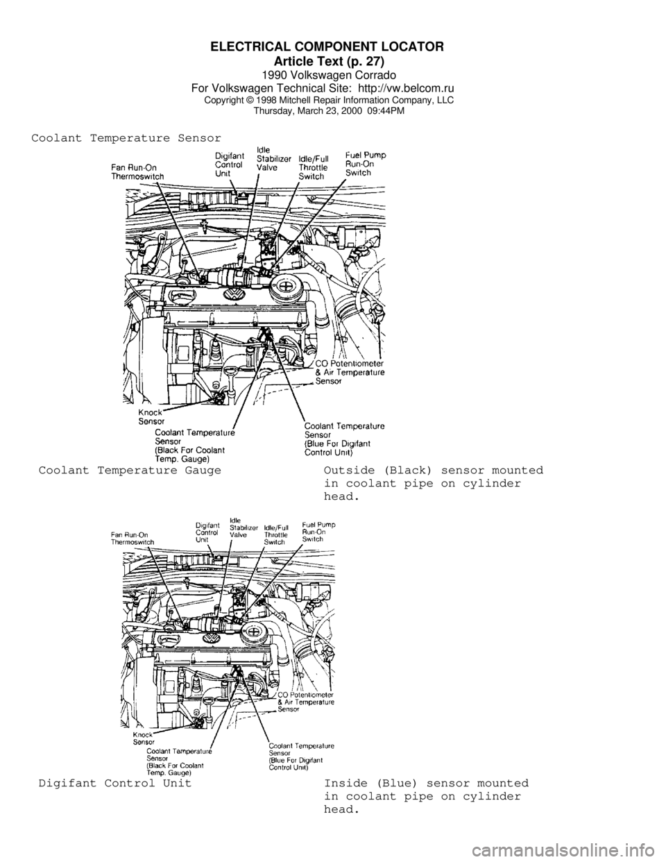
Coolant Temperature Sensor Coolant Temperature Gauge Outside (Black) sensor mounted
in coolant pipe on cylinder
head. Digifant Control Unit Inside (Blue) sensor mounted
in coolant pipe on cylinder
head.
Page 503 of 906

EMISSION CONTROL VISUAL INSPECTION PROCEDURES
Article Text (p. 9)
1990 Volkswagen Corrado
For Volkswagen Technical Site: http://vw.belcom.ru
Copyright © 1998 Mitchell Repair Information Company, LLC
Thursday, March 23, 2000 09:44PMFig. 10: Typical Negative Backpressure EGR Valve
Courtesy of General Motors Corp.
Digital EGR Valve
The digital EGR valve operates independently of engine
manifold vacuum. This valve controls EGR flow through 3 orifices.
These 3 orifices are opened and closed by electric solenoids. The
solenoids are, in turn, controlled by the Electronic Control Module
(ECM). When a solenoid is energized, the armature with attached shaft
and swivel pintle is lifted, opening the orifice. See Fig. 11.
The ECM uses inputs from the Coolant Temperature Sensor
(CTS), Throttle Position Sensor (TPS) and Mass Airflow (MAF) sensors
to control the EGR orifices to make 7 different combinations for
precise EGR flow control. At idle, the EGR valve allows a very small
amount of exhaust gas to enter the intake manifold. This EGR valve
normally operates above idle speed during warm engine operation.
Verify EGR valve is present and not modified or purposely
damaged. Ensure thermal vacuum switches, pressure transducers, speed
switches, etc., (if applicable) are not by-passed or modified. Ensure
vacuum hose(s) to EGR valve is not plugged. Ensure electrical
connector to EGR valve is not disconnected.
Page 545 of 906
ENGINE OVERHAUL PROCEDURES - GENERAL INFORMATION
Article Text (p. 36)
1990 Volkswagen Corrado
For Volkswagen Technical Site: http://vw.belcom.ru
Copyright © 1998 Mitchell Repair Information Company, LLC
Thursday, March 23, 2000 09:44PM
to ensure correct amount of oil has filled crankcase. Check oil level
while pre-oiling.
If pressure oiler is not available, disconnect ignition
system. Remove oil pressure sending unit and replace with oil pressure
test gauge. Using starter motor, rotate engine starter until gauge
shows normal oil pressure for several seconds. DO NOT crank engine
for more than 30 seconds to avoid starter motor damage.
Ensure oil pressure has reached the most distant point from
the oil pump. Reinstall oil pressure sending unit. Reconnect ignition
system.
INITIAL START-UP
Start the engine and operate engine at low speed while
checking for coolant, fuel and oil leaks. Stop engine. Recheck coolant
and oil level. Adjust if necessary.
CAMSHAFT
Break-in procedure is required when a new or reground
camshaft has been installed. Operate and maintain engine speed between
1500-2500 RPM for approximately 30 minutes. Procedure may vary due to
manufacturers recommendations.
PISTON RINGS
Piston rings require a break-in procedure to ensure seating
of rings to cylinder walls. Serious damage may occur to rings if
correct procedures are not followed.
Extremely high piston ring temperatures are produced obtained
during break-in process. If rings are exposed to excessively high RPM
or high cylinder pressures, ring damage can occur. Follow piston ring
manufacturer's recommended break-in procedure.
FINAL ADJUSTMENTS
Check or adjust ignition timing and dwell (if applicable).
Adjust valves (if necessary). Adjust carburetion or injection idle
speed and mixture. Retighten cylinder heads (if required). If
cylinder head or block is aluminum, retighten bolts when engine is
cold. Follow the engine manufacturer's recommended break-in procedure
and maintenance schedule for new engines.
NOTE: Some manufacturer's require that head bolts be retightened
after specified amount of operation. This must be done to
prevent head gasket failure.
END OF ARTICLE
Page 558 of 906

F - BASIC TESTING
Article Text (p. 13)
1990 Volkswagen Corrado
For Volkswagen Technical Site: http://vw.belcom.ru
Copyright © 1998 Mitchell Repair Information Company, LLC
Thursday, March 23, 2000 09:44PM
DISTRIBUTOR
HALL EFFECT SENDER
1) Remove coil secondary and attach to ground. Disconnect
Hall Effect sender wire at the distributor. Using a LED Test Light (US
1115), check for voltage between outer terminals of connector. See
Fig. 5 or 8. With ignition on, light should be on. If not, check
wiring for short or open circuit. If wiring is okay, replace Digifant
control unit.
2) If light came on in step 1), reconnect Hall Effect sender
harness connector. Pull back Hall Effect sender boot to expose contact
terminals. Apply LED Test Light (US 1115) probe to center contact and
battery positive terminal. See Fig. 5. Observe test light while
cranking engine. If test light blinks, Hall Effect sender is okay. If
not, replace Hall Effect-sender.
IDLE SPEED, CO LEVEL & IGNITION TIMING
Ensure idle speed, CO level and base ignition timing are set
to specification. If necessary, see ON-VEHICLE ADJUSTMENTS article.
IDLE SPEED & CO LEVEL TABLEÄÄÄÄÄÄÄÄÄÄÄÄÄÄÄÄÄÄÄÄÄÄÄÄÄÄÄÄÄÄÄÄÄÄÄÄÄÄÄÄÄÄÄÄÄÄÄÄÄÄÄÄÄÄÄÄÄÄÄÄApplication Idle RPM CO Level %
All Models ............ 800-1000 .............. 0.3-1.2%
ÄÄÄÄÄÄÄÄÄÄÄÄÄÄÄÄÄÄÄÄÄÄÄÄÄÄÄÄÄÄÄÄÄÄÄÄÄÄÄÄÄÄÄÄÄÄÄÄÄÄÄÄÄÄÄÄÄÄÄÄIGNITION TIMING TABLE (Degrees BTDC @ RPM)
ÄÄÄÄÄÄÄÄÄÄÄÄÄÄÄÄÄÄÄÄÄÄÄÄÄÄÄÄÄÄÄÄÄÄÄÄÄÄÄÄÄÄÄÄÄÄÄÄÄÄÄÄÄÄÄÄÄÄÄÄApplication Checking Adjusting
1.8L ............... 4-8 @ 2250-2350 . 5-7 @ 2250-2350
2.0L ................ 4-8 @ 770-830 ...... 5-7 @ 770-830
2.1L (1) ........... 4-8 @ 2250-2350 . 5-7 @ 2250-2350
(1) - With coolant temperature sensor disconnected.
ÄÄÄÄÄÄÄÄÄÄÄÄÄÄÄÄÄÄÄÄÄÄÄÄÄÄÄÄÄÄÄÄÄÄÄÄÄÄÄÄÄÄÄÄÄÄÄÄÄÄÄÄÄÄÄÄÄÄÄÄ SUMMARY
If no faults were found while performing F - BASIC TESTING,
proceed to H - TESTS W/CODES article for diagnosis by symptom (i.e.,
ROUGH IDLE, NO START, etc.) or intermittent diagnostic procedures.
END OF ARTICLE
Page 572 of 906
GENERAL COOLING SYSTEM SERVICING
Article Text (p. 2)
1990 Volkswagen Corrado
For Volkswagen Technical Site: http://vw.belcom.ru
Copyright © 1998 Mitchell Repair Information Company, LLC
Thursday, March 23, 2000 09:45PM
To flush engine, remove thermostat and replace housing.
Connect flushing gun to water outlet of engine. Flush using short air
bursts until water runs clean.
Heater Core
Flush heater core as described for radiator. Ensure heater
control valve is set to maximum heat position before flushing heater.
REFILLING
To prevent air from being trapped in engine block, engine
should be running when refilling cooling system. After system is full,
continue running engine until thermostat is open, then recheck fill
level. Do not overfill system.
TESTING
THERMOSTAT
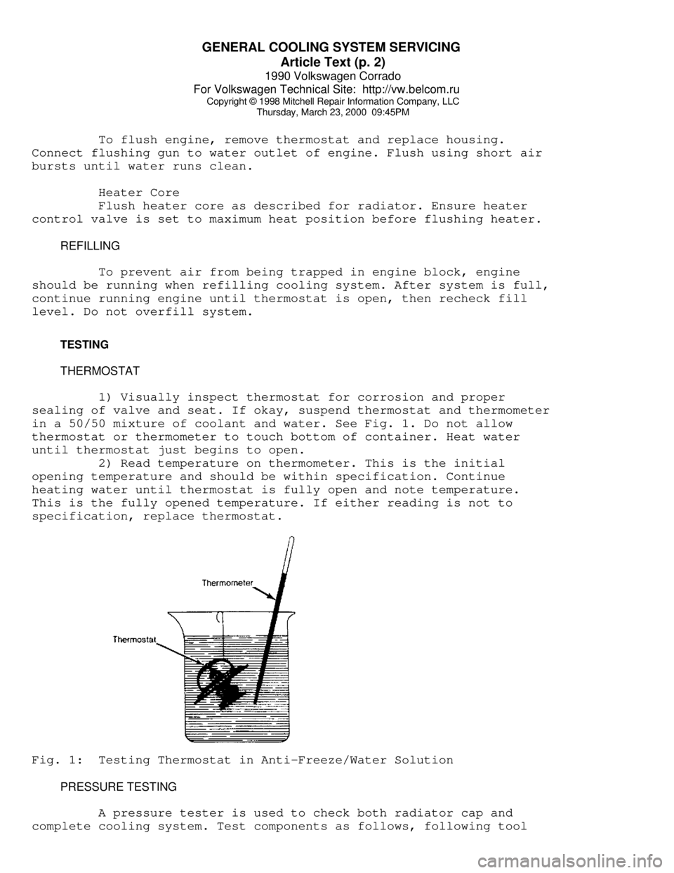
1) Visually inspect thermostat for corrosion and proper
sealing of valve and seat. If okay, suspend thermostat and thermometer
in a 50/50 mixture of coolant and water. See Fig. 1. Do not allow
thermostat or thermometer to touch bottom of container. Heat water
until thermostat just begins to open.
2) Read temperature on thermometer. This is the initial
opening temperature and should be within specification. Continue
heating water until thermostat is fully open and note temperature.
This is the fully opened temperature. If either reading is not to
specification, replace thermostat.Fig. 1: Testing Thermostat in Anti-Freeze/Water Solution
PRESSURE TESTING
A pressure tester is used to check both radiator cap and
complete cooling system. Test components as follows, following tool
Page 575 of 906
H - TESTS W/O CODES
Article Text (p. 2)
1990 Volkswagen Corrado
For Volkswagen Technical Site: http://vw.belcom.ru
Copyright © 1998 Mitchell Repair Information Company, LLC
Thursday, March 23, 2000 09:45PM
WILL NOT START OR STARTS HARD COLD (CRANKS OKAY)
* Check ignition fuse (if equipped).
* Check fuel pump fuse and fuel pump relay.
* Verify air intake system is unrestricted.
* Ensure fuel system pressure and volume are correct.
* Check cold start valve and thermo time switch operation.
* Ensure airflow sensor plate is in rest position. Adjust as
necessary.
* Test coolant temperature sensor and wiring. Repair or replace
as required.
* Check for poor ignition ground (1.8L & 2.0L 16-valve engines).
* Check for poor quality or contaminated fuel.
* Check condensation (water) in fuel tank causing fuel pump to
freeze (cold climate).
* Check exhaust system for restriction.
* Test airflow meter. Replace if faulty.
* Ensure sufficient secondary spark is available.
* Check air induction system for cracks or restriction.
* Ensure vacuum hoses are not disconnected or damaged.
* Ensure fuel system residual pressure is correct.
* Ensure fuel injector operation is correct.
* Ensure EGR valve operation is correct and valve closes
completely (if equipped).
* Check for cracks or poor connections at throttle body.
* Ensure ignition and valve timing are correct.
* Check ignition coil primary connections and wiring harness.
* Ensure ignition coil resistance is within specification.
* Check air temperature sensor operation (if equipped).
* Ensure electrical harness and connectors are not broken or loose.
* Ensure ECU or ignition control unit has correct voltage supply
and is properly grounded.
* Ensure engine has sufficient compression.
* Inspect intake air components for leaking hoses, connections or
cracks. Repair as required.
WILL NOT START OR STARTS HARD HOT (CRANKS OKAY)
* Check ignition fuse (if equipped).
* Check fuel system fuse and fuel pump relay.
* Check for poor quality or contaminated fuel.
* Check condensation (water) in fuel tank causing fuel pump to
freeze (cold climate).
* Check exhaust system for restriction.
* Check cold start valve and thermo time switch operation.
* Check fuel system and control system pressure. Replace pressure
regulator if necessary.
* Check residual fuel pressure. Replace fuel pump check valve or
fuel accumulator as necessary.
* Check oxygen sensor system operation.
* Ensure airflow sensor plate is in rest position. Adjust as
Page 576 of 906
H - TESTS W/O CODES
Article Text (p. 3)
1990 Volkswagen Corrado
For Volkswagen Technical Site: http://vw.belcom.ru
Copyright © 1998 Mitchell Repair Information Company, LLC
Thursday, March 23, 2000 09:45PM
necessary.
* Ensure injector spray patterns and volume are correct. Replace
faulty injectors.
* Inspect fuel lines and connections for leaks.
* Check carbon canister solenoid valves (CIS-E Motronic).
* Test airflow meter. Replace if faulty.
* Ensure sufficient secondary spark is available.
* Check air induction system for cracks or restriction.
* Check airflow sensor plate rest position.
* Ensure vacuum hoses are not disconnected or damaged.
* Ensure EGR valve operation is correct and valve closes
completely (if equipped).
* Check for cracks or poor connections at throttle body.
* Ensure ignition and valve timing are correct.
* Check ignition coil primary connections and wiring harness.
* Ensure ignition coil resistance is within specification.
* Check air temperature sensor operation.
* Check coolant temperature sensor operation.
* Ensure electrical harness and connectors are not broken or loose.
* Ensure ECU or ignition control unit has correct voltage supply
and is properly grounded.
* Ensure engine has sufficient compression.
ENGINE STALLS OR IDLES ROUGH
* Check fuel system and control system pressure. Replace pressure
regulator if necessary.
* Check cold start valve for leaking (engine warm).
* Ensure injector spray patterns and volume are correct. Replace
faulty injectors.
* Test coolant temperature sensor and wiring. Repair or replace
as required.
* Inspect intake air components for leaking hoses, connections or
cracks. Repair as required.
* Ensure airflow sensor plate movement and rest position. Adjust
as necessary.
* Test idle switch and idle air stabilizer valve.
* Perform system electrical checks.
* Check airflow meter. Replace if faulty.
* Ensure idle RPM is correct.
* Check auxiliary air by-pass regulator.
* Check fuel injector electrical connections.
* Use stethoscope to verify fuel injectors are operating.
* Ensure sufficient secondary spark is available in all cylinders.
* Verify vacuum hose routing is correct and there are no
vacuum leaks.
* Check idle stabilizer operation.
* Check for EGR system malfunction (if equipped).
* Check O2 sensor operation.
* Check for distortion or cracks in fuel injector(s) plastic
connecting flange(s).
* Check for use of poor quality fuel containing insufficient
Page 577 of 906

H - TESTS W/O CODES
Article Text (p. 4)
1990 Volkswagen Corrado
For Volkswagen Technical Site: http://vw.belcom.ru
Copyright © 1998 Mitchell Repair Information Company, LLC
Thursday, March 23, 2000 09:45PM
cleaning additives. Prolonged use of poor quality fuel can
cause injector clogging and carbon build-up on intake system.
ENGINE MISFIRES OR HESITATES
CIS-E & CIS-E MOTRONIC
* Ensure injector spray patterns and volume are correct. Replace
faulty injectors.
* Check fuel system and control system pressure. Replace pressure
regulator if necessary.
* Check Oxygen (O2) sensor system operation.
* Check fuel lines and connections for leaks.
* Test coolant temperature sensor and wiring. Repair or replace
as required.
* Check airflow meter and throttle switch. Replace if faulty.
* Ensure vacuum hoses are not disconnected or damaged.
* Ensure electrical harness connectors and wires are not
broken or loose.
* Check cold start valve for leaking (engine warm).
DIGIFANT II
* Check airflow sensor flap and sensor resistance. Replace
if faulty.
* Inspect intake air components for leaking hoses, connections
or cracks. Repair as required.
* Test intake air preheating system. Replace faulty components
as required.
* Check fuel system and control system pressure. Replace pressure
regulator if necessary.
* Ensure vacuum hoses are not disconnected or damaged.
* Ensure electrical harness connectors and wires are not
broken or loose.
* Check cold start valve for leaking (engine warm).
* Check coolant temperature sensor operation.
* Check Oxygen (O2) sensor voltage output.
EXCESSIVE FAST IDLE
* Inspect accelerator pedal and cable for worn parts or binding.
* Test idle switch (if equipped).
* Test auxiliary air regulator and replace if necessary
(if equipped).
* Inspect throttle valve and adjust or replace as required.
* Check carbon canister solenoid valves (CIS-E Motronic).
* Test idle boost valve system operation (1.8L 8-valve engine
only). Replace faulty parts as necessary.
* Test coolant temperature sensor and wiring (Digifant II). Repair
or replace as required.
* Check throttle cable adjustment.
* Verify vacuum hose routing is correct.