Page 929 of 2103
MANUAL TRANSAXLE OVERHAUL
Input Shaft
4
q 5
6
11
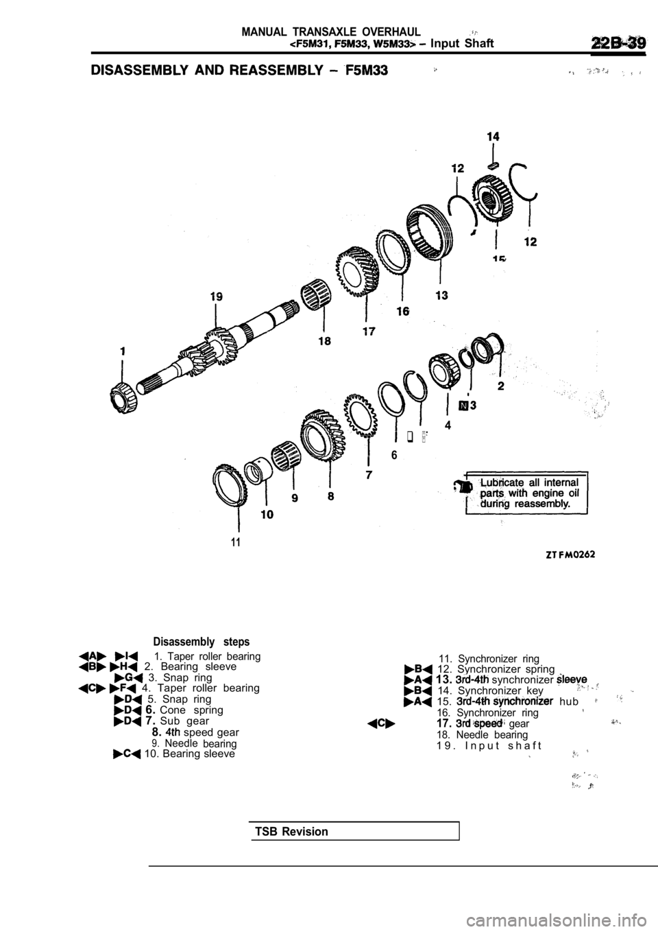
Disassembly steps
1. Taper roller bearing 2. Bearing sleeve
3. Snap ring 4. Taper roller bearing
5. Snap ring 6. Cone spring 7. Sub gear
8.
speed gear9.Needle bearing 10. Bearing sleeve
11. Synchronizer ring 12. Synchronizer spring 13. synchronizer 14. Synchronizer key 15. hub
16. Synchronizer ring17. gear
18. Needle bearing1 9 . I n p u t s h a f t
TSB Revision
Page 932 of 2103
MANUAL TRANSAXLE OVERHAUL
Input Shaft
gear
spee
gear
side
Identificationmark
Spring
stepped
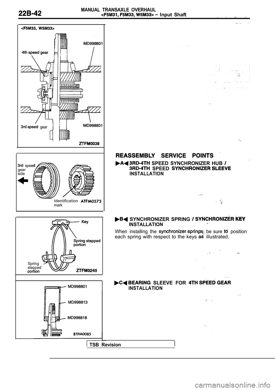
SPEED SYNCHRONIZER HUB
SPEED
INSTALLATION
SYNCHRONIZER SPRING
INSTALLATION
When installing the be sure position
each spring with respect to the keys illustrated.
SLEEVE FOR
INSTALLATION
TSB Revision
Page 937 of 2103
MANUAL TRANSAXLE OVERHAUL
wear
Da
S Y N C H R O N I Z E R K E Y A N D
(1) for wear of key
(2) the spring for deform&i&
age.
SPEED GEARS
(1) Check the synchronizer cone for rough surface, damage
and wear.
(2) Check the gear bore and front and rear ends for damage
and wear.
TSB Revision
Page 938 of 2103
MANUAL TRANSAXLE OVERHAUL
Intermediate Gear ,
INTERMEDIATE GEAR 2220018004~
DISASSEMBLY AND REASSEMBLY
. .
‘I
7
8
7
Lubricate all internalparts with engine oil
during reassembly.
Disassembly steps
1. Snap ring
2. Taper roller bearing 9. Synchronizer key
3. Bearing sleeve 10. speed synchronizer hub
4.
speed gear 11. Synchronizer ring
12.
5. speed13.N e e d l e g e a r6.Needle bearing
Synchronizer ring bearing
7. Synchronizer spring 14. Taper roller bearing
8. speed synchronizer sleeve 15. Intermediate gear
TSB RevisionI
Page 939 of 2103
MANUAL TRANSAXLE.: OVERHAUL
Gear
.,
DISASSEMBLY AND REASSEMBLY
Disassembly steps
1. Snap ring2. Taper roller bearing Bearing sleeve4. speed gear5. Needle bearing6. Synchronizer ring7. Synchronizer spring8. speed synchronizer
9. Synchronizer key
TSB Revision
speed
11.12. Synchronizer cone 13. Synchronizer inner speed gear
15. Needle
16. Taper roller bearing 1 7 .
7
. . , ___
Page 941 of 2103
MANUAL TRANSAXLE OVERHAUL
bear
Identification mark RINGS
GEAR INSTALLATION .
The speed gear and of
r i n g s h a v e a n i d e n t i f i c a t i o n m a r k .
Clutch housing
Identification markTooth missing here
Synchronizer key
1 SPEED
SYNCHRONIZER KEY
SLEEVE
(1) the speed
as
(2) The synchronizer sleeve has tooth missing at si x portions.
Assemble the hub to the sleeve in such a way that t he
center tooth
between two missing teeth will touch
the synchronizer key.
SYNCHRONIZER SPRING INSTALLATION
When installing the synchronizer springs, be sure t o position
each spring with respect to the keys as illustrated.
BEARING SLEEVE INSTALLATION
TSB Revision
. .
Page 944 of 2103
MANUAL TRANSAXLE OVERHAUL
Intermediate Gear
the outer ring, inner ring and cone, and press them
onto the clutch gear. Check clearance and replace
if
is below the limit value..
Limit: 0.5 mm in.)
Replace the outer ring, inner ring cone, as
TSB Revision
SYNCHRONIZER SLEEVE AND HUB
(1) Combine the synchronizer
and hub and check
that they slide smoothly.
(2) Check that the sleeve is free from damage
its
front and rear ends.
(3) Check for wear of the end contact
each speed gear).
Caution
Replace the synchronizer hub and sleeve as a set.
SYNCHRONIZER KEY AND SPRING
(1)Check for wear of the protrusion.
(2) Check the spring for break-
age.
SPEED GEARS (1) Check the bevel gear and clutch gear teeth for damage
and wear.
(2) Check the synchronizer cone for damage
and wear.
(3) Check the gear bore and front arid rear ends fo r
and wear.
Page 986 of 2103
Output Disassembly/
MANUAL TRANSAXLE
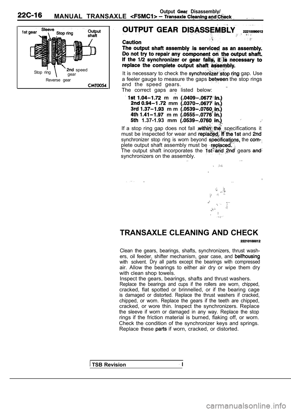
Stop ring speedgear
Reverse gearIt is necessary to check the gap. Use
a feeler gauge to measure the gaps
the stop rings
and the speed gears.
The correct gaps are listed below:
.
m m
mm
m m
m m
1.37-1.93 mm .If a stop ring gap does not fall specifications it
must be inspected for wear and
and
synchronizer stop ring is worn beyond the
plete output shaft assembly must be
The output shaft incorporates the gears
synchronizers on the assembly.
.
.. .
TRANSAXLE CLEANING AND CHECK
Clean the gears, bearings, shafts, synchronizers, t hrust wash-
ers, oil feeder, shifter mechanism, gear case, and
with solvent. Dry all parts except the bearings with compressed
air. Allow the bearings to either air dry or wipe t
hem dry
with clean shop towels. Inspect the gears, bearings, shafts and thrust wash ers.
Replace the bearings and cups if the rollers are wo rn, chipped,
cracked, flat spotted or brinnelled, or if the bearing cage
is damaged or distorted. Replace the thrust washers if cracked,
chipped, or worn. Replace the gears if the teeth are chipped,
cracked, or wore thin. Inspect the synchronizers. R eplace
the sleeve if worn or damaged in any way. Replace t he stop
rings if the friction material is burned, flaking off, or worn.
Check the condition of the synchronizer keys and sp rings.
Replace these
if worn, cracked, or distorted.
TSB Revision I