1990 MITSUBISHI SPYDER check transmission fluid
[x] Cancel search: check transmission fluidPage 1149 of 2103
AUTOMATIC TRANSAXLE
ENGINE (NON-TURBO)> Troubleshooting
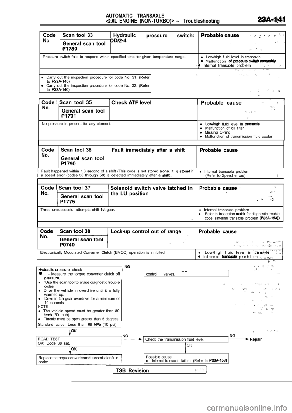
Code Scan tool 33Hydraulicpressureswitch:
No.General scan tool
Pressure switch falls to respond within specified t ime for given temperature range.
l Low/high fluid level in transaxle Malfunction Internal transaxle problem
,l Carry out the inspection procedure for code No. 31. (Refertol Carry out the inspection procedure for code No. 32. (Refer
to
Code Scan tool 35 Check level . Probable cause No.General scan tool
No pressure is present for any element.l fluid level in l
Malfunction of oil filter
l Missing O-ring
l Malfunction of transmission fluid cooler
Code Scan tool 38
Fault immediately after a shift Probable cause
No.General scan tool
Fault happened within 1.3 second of a shift (This code is not stored alone. It if
a speed error (codes through 58) is detected immediately after a l Internal transaxle problem
(Refer to Speed errors) I
Code
Scan tool 37 Solenoid switch valve latched in
No.General scan tool the LU position
Three unsuccessful attempts shift gear.
Probable
l
Internal transaxle problemlRefer to Inspection for diagnostic trouble
code. (Internal transaxle problem
Lock-up control out of rangeProbable cause
Electronically Modulated Converter Clutch (EMCC) op eration is inhibitedl L o w / h i g h f l u i d l e v e l i n I n t e r n a l p r o b l e m
checkNGI -..< .
l - Measure the torque converter clutch offcontrol valves.
l‘Use the scan tool to erase diagnostic troublecodes.l Drive the vehicle in overdrive until it is fully
warmed up.
lDrive in gear overdrive for a minimum of10 seconds.NOTEl The vehicle speed must be greater than 80 (50 mph).lThrottle must be open greater than 6 degrees.
Standard value: Less than 69 (10 psi)
ROAD TESTOK: Code 38 set. Check the transmission fluid level.OK
NG Repair
Replacethetorqueconverterandtransmissionfluid
cooler.
Possible cause:lInternal transaxle failure. (Refer to
TSB Revision
Page 1156 of 2103
AUTOMATIC TRANSAXLE
ENGINE (NON-TURBO)> Troubleshooting
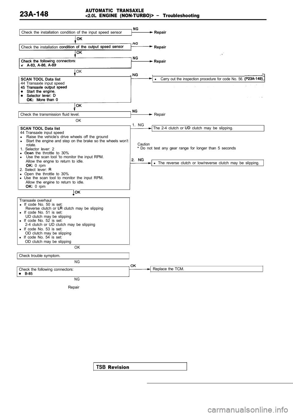
NGCheck the installation condition of the input speed sensor Repair
OK
NGCheck the installation Repair
NG Repair
l
OK
SCAN TOOL Data list lCarry out the inspection procedure for code No. 56.
44 Transaxle input speed
Check the transmission fluid level.
OK
SCAN TOOL Data list
44 Transaxle input speed l Raise the vehicle’s drive wheels off the ground
NG Repair
1. NG
The 2-4 clutch or clutch may be slipping.
l Start the engine and step on the brake so the wheel s won’t
rotate.1. Selector lever: 2
l the throttle to 30%
Caution Do not test any gear range for longer than 5 secon ds
l Use the scan tool ‘to monitor the input RPM.
Allow the engne to return to idle. OK: 0 rpm l
The reverse clutch or low/reverse clutch may be sli pping.
2. Select lever:
l Open the throttle to 30%
l Use the scan tool to monitor the input RPM.
Allow the enaine to return to idle.
OK: 0 rpm
Transaxle overhaul
l If code No. 50 is set:
Reverse clutch or
clutch may be slipping
l If code No. 51 is set:
UD clutch may be slipping
l If code No. 52 is set:
2-4 clutch or UD clutch may be slipping
l If code No. 53 is set:
OD clutch may be slipping
l If code No. 54 is set:
OD clutch may be slipping
OK
Check trouble symptom.
NG
Check the following connectors: Replace the TCM.
N G
TSBRevision
Repair
Page 1159 of 2103
AUTOMATIC .
.
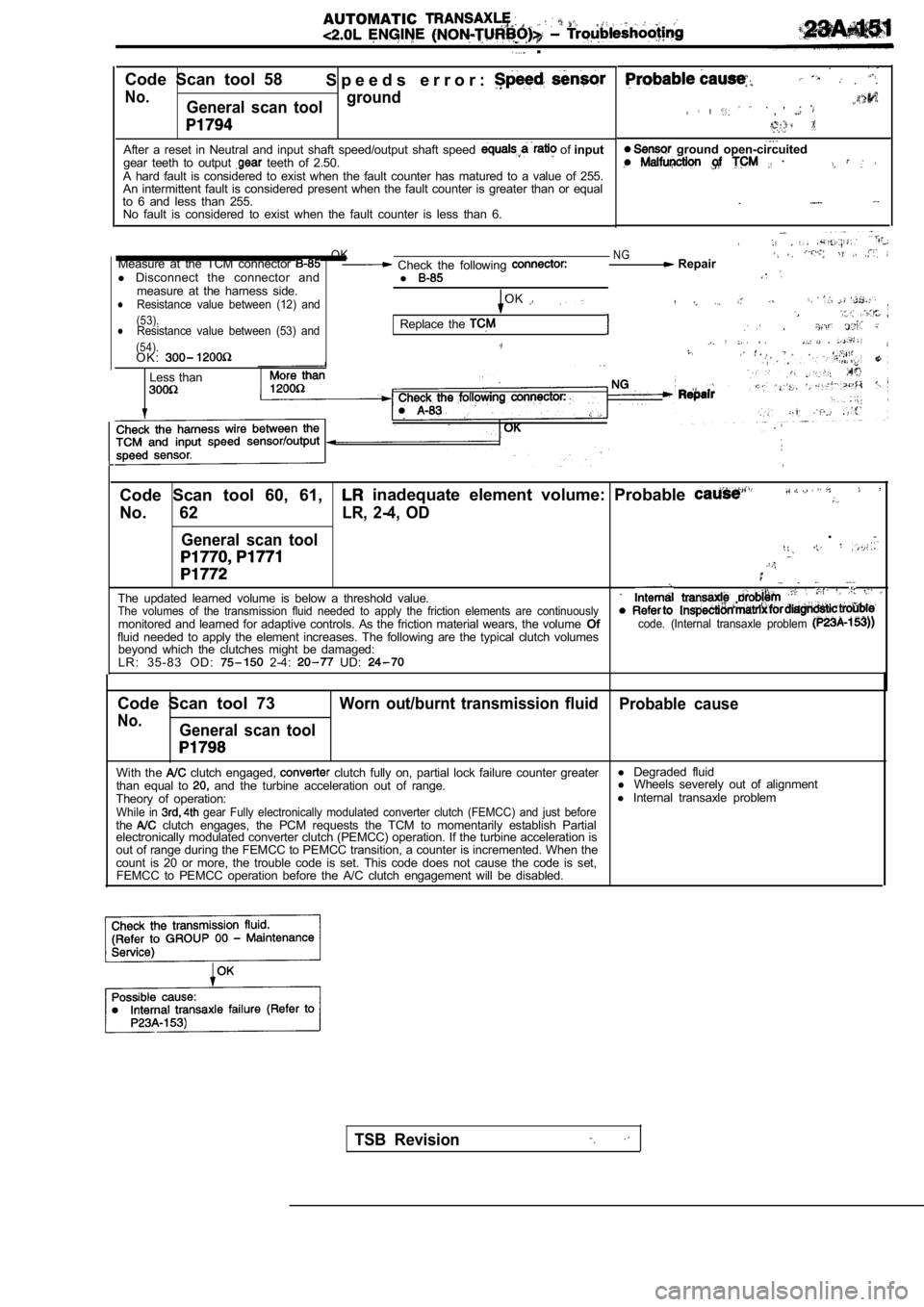
Code Scan tool 58 S p e e d s e r r o r :
No.General scan toolground
After a reset in Neutral and input shaft speed/outp
ut shaft speed of input
gear teeth to output teeth of 2.50.
A hard fault is considered to exist when the fault counter has matured to a value of 255.
An intermittent fault is considered present when th e fault counter is greater than or equal
to 6 and less than 255. No fault is considered to exist when the fault coun ter is less than 6.
.
. , ,
. .
ground open-circuited
OKNGMeasure at the TCM connector Check the following Repair
l Disconnect the connector and
l
measure at the harness side.Resistance value between (12) andOKl
(53).lResistance value between (53) andReplace the . (54).O K :.
Less than
Code Scan tool 60, 61, inadequate element volume: Probable
No. 62LR, 2-4, OD
General scan tool
.
The updated learned volume is below a threshold val ue..The volumes of the transmission fluid needed to app
ly the friction elements are continuouslymonitored and learned for adaptive controls. As the friction material wears, the volume Ofcode. (Internal transaxle problem fluid needed to apply the element increases. The fo llowing are the typical clutch volumes
beyond which the clutches might be damaged:
L R : 3 5 - 8 3 O D :
2-4: UD:
Code Scan tool 73Worn out/burnt transmission fluid Probable cause
No.General scan tool
With the clutch engaged, clutch fully on, partial lock failure counter greaterl
Degraded fluid
than equal to and the turbine acceleration out of range. l
Wheels severely out of alignment
Theory of operation: l
Internal transaxle problem
While in gear Fully electronically modulated converter clut ch (FEMCC) and just beforethe clutch engages, the PCM requests the TCM to moment arily establish Partial
electronically modulated converter clutch (PEMCC) o peration. If the turbine acceleration is
out of range during the FEMCC to PEMCC transition, a counter is incremented. When the
count is 20 or more, the trouble code is set. This code does not cause the code is set,
FEMCC to PEMCC operation before the A/C clutch enga gement will be disabled.
TSB Revision
Page 1174 of 2103
AUTOMATIC TRANSAXLE
ENGINE (NON-TURBO)> On-vehicle Service
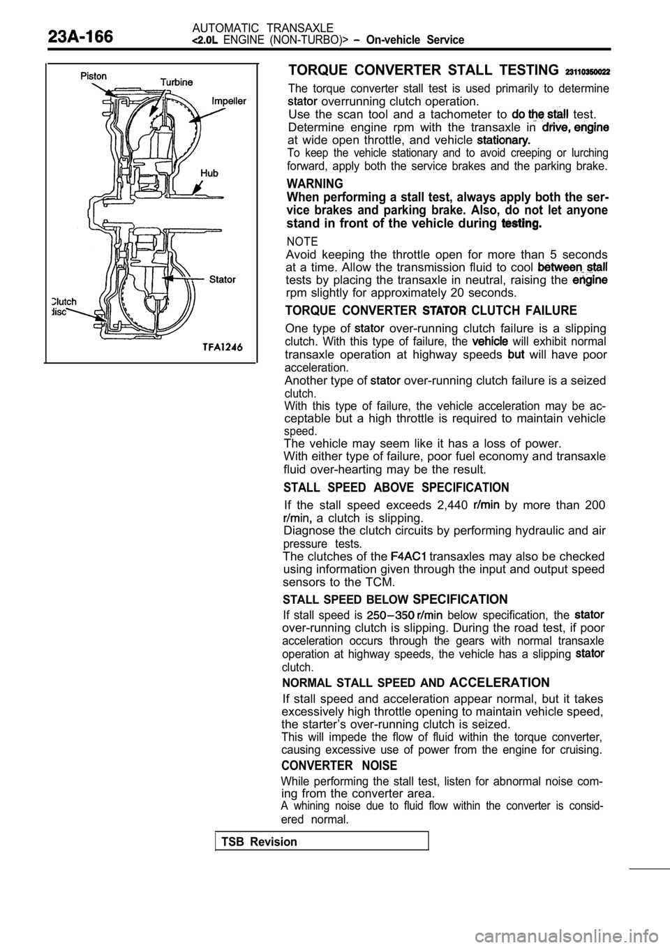
TORQUE CONVERTER STALL TESTING
The torque converter stall test is used primarily to determine
overrunning clutch operation.
Use the scan tool and a tachometer to
test.
Determine engine rpm with the transaxle in
at wide open throttle, and vehicle
To keep the vehicle stationary and to avoid creepin g or lurching
forward, apply both the service brakes and the parking brake.
WARNING
When performing a stall test, always apply both the ser-
vice brakes and parking brake. Also, do not let any one
stand in front of the vehicle during
NOTE
Avoid keeping the throttle open for more than 5 seconds
at a time. Allow the transmission fluid to cool
tests by placing the transaxle in neutral, raising the
rpm slightly for approximately 20 seconds.
TORQUE CONVERTER CLUTCH FAILURE
One type of over-running clutch failure is a slipping
clutch. With this type of failure, the will exhibit normal
transaxle operation at highway speeds will have poor
acceleration.
Another type of over-running clutch failure is a seized
clutch.
With this type of failure, the vehicle acceleration may be ac-
ceptable but a high throttle is required to maintai n vehicle
speed.
The vehicle may seem like it has a loss of power.
With either type of failure, poor fuel economy and transaxle
fluid over-hearting may be the result.
STALL SPEED ABOVE SPECIFICATION
If the stall speed exceeds 2,440 by more than 200
a clutch is slipping.
Diagnose the clutch circuits by performing hydrauli c and air
pressure tests.
The clutches of the transaxles may also be checked
using information given through the input and outpu t speed
sensors to the TCM.
STALL SPEED BELOW SPECIFICATION
If stall speed is below specification, the
over-running clutch is slipping. During the road te st, if poor
acceleration occurs through the gears with normal t ransaxle
operation at highway speeds, the vehicle has a slip ping
clutch.
NORMAL STALL SPEED AND ACCELERATION
If stall speed and acceleration appear normal, but it takes
excessively high throttle opening to maintain vehic le speed,
the starter’s over-running clutch is seized.
This will impede the flow of fluid within the torqu e converter,
causing excessive use of power from the engine for cruising.
CONVERTER NOISE
While performing the stall test, listen for abnormal noise com-
ing from the converter area.
A whining noise due to fluid flow within the conver ter is consid-
ered normal.
TSB Revision
Page 1363 of 2103
A U T O M A T I C “ T R A N S A X L E .
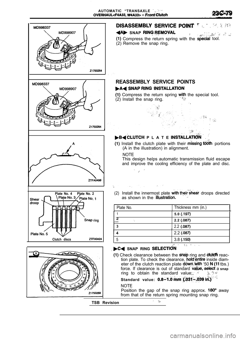
SNAP
Compress the return spring with thetool.
(2) Remove the snap ring.
REASSEMBLY SERVICE POINTS
Compress the return spring the special tool.
(2) Install the snap ring.
,
P L A T E
Install the clutch plate with their portions
(A in the illustration) in alignment.
NOTE
This design helps automatic transmission fluid esca pe
and improve the cooling efficiency of the plate and disc.
Plate No. 4 Plate No. 2
ring
Clutch discs
(2)Install the innermost plate droops directed
as shown in the
Plate No.Thickness mm (in.)
15.0
2.2
32.2
Position the gap of the snap ring approx. away
from that of the return spring mounting snap ring.
TSB Revision
2.2
53.8
SNAP RING
Check clearance between the ring and reac-
tion plate. To check the clearance, inside diam-
eter of the clutch reaction plate ‘50 tbs.)
force. If clearance is out of standard a snap
ring to obtain the standard value;,
S t a n d a r d v a l u e :
NOTE
Page 1365 of 2103
A U T O M A T I C
Rear
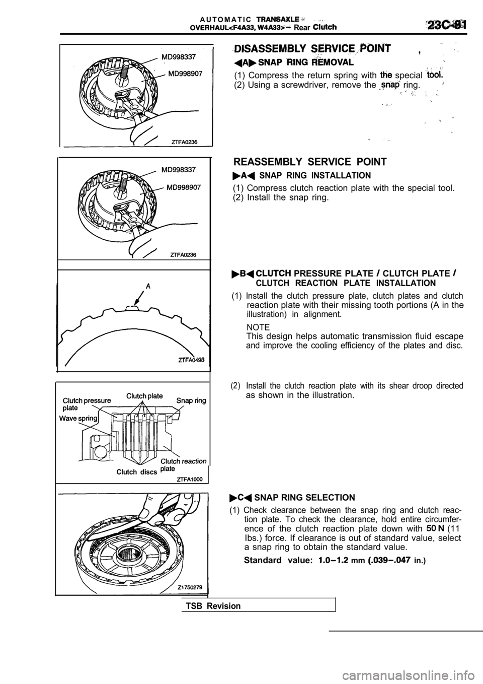
,
(1) Compress the return spring with special
(2) Using a screwdriver, remove the ring.
Clutch discs
REASSEMBLY SERVICE POINT
SNAP RING INSTALLATION
(1) Compress clutch reaction plate with the special tool.
(2) Install the snap ring.
PRESSURE PLATE CLUTCH PLATE
CLUTCH REACTION PLATE INSTALLATION
(1) Install the clutch pressure plate, clutch plate s and clutch
reaction plate with their missing tooth portions (A in the
illustration) in alignment.
NOTE
This design helps automatic transmission fluid esca pe
and improve the cooling efficiency of the plates and disc.
(2)Install the clutch reaction plate with its shear droop directed
as shown in the illustration.
SNAP RING SELECTION
(1) Check clearance between the snap ring and clutc h reac-
tion plate. To check the clearance, hold entire cir cumfer-
ence of the clutch reaction plate down with (11
Ibs.) force. If clearance is out of standard value, select
a snap ring to obtain the standard value.
Standard value:
mm in.)
TSB Revision