Page 273 of 391

.-AUTOMATIC TRANSAXLE
- Transaxle Control21-49
Transaxlecontrol unit
Eel
6017!au72
THROmE POSITION SENSOR
The throttle position
SenSOr is installed on the throttle body.
The throttle position sensor Of variable resistor type
senses thethrottle valve
opening.
As the throttle shaft turns, the resistance i.e. output voltage of
throttle position sensor changes. This throttle position sensor
output voltage is input to the transaxle control unit to compute
the throttle opening.
The throttle position sensor output voltage can be adjusted by
turning the throttle position sensor body.
Throttle position sensor output characteristics
5
1
0’ ’10 20 30 40 50 60 70 80 82Totally Throttle valve opening (degrees) Totally
closedopened7FUO75control switchKICKDOWN SERVO SWITCH
The adjust sleeve and the retainer constitute the contacts of
the kickdown servo switch. The switch detects the position of
the kickdown piston just before the kickdown brake is applied,
and sends the signal to the transaxle control unit.
When the kickdown servo is not in operation, the switch
contacts are kept closed.
When the hydraulic pressure is applied to the kickdown servo
and the piston is operated,
the’adjust sleeve separates from
the retainer, turning off the. switch.
Using the kickdown servo switch OFF signal as its standard,
thetransaxle control unit controls the 2nd pressure before, and
during application of the brake by actuating the pressure
control solenoid valve.
OVERDRIVE CONTROL SWITCH
When the overdrive control switch is ON, operation is as a
O-speed automatic transaxle.
When the overdrive control switch is OFF, the indicator light
(within the combination meter) is illuminated, and operation
isas a
3-speed automatic transaxle.
Page 274 of 391

21-50AUTOMATIC TRANSAXLE - Transaxle Control
Vehicle
sensorspeedTerminal voltage
(VI
1
5
\*Fluidtemperature
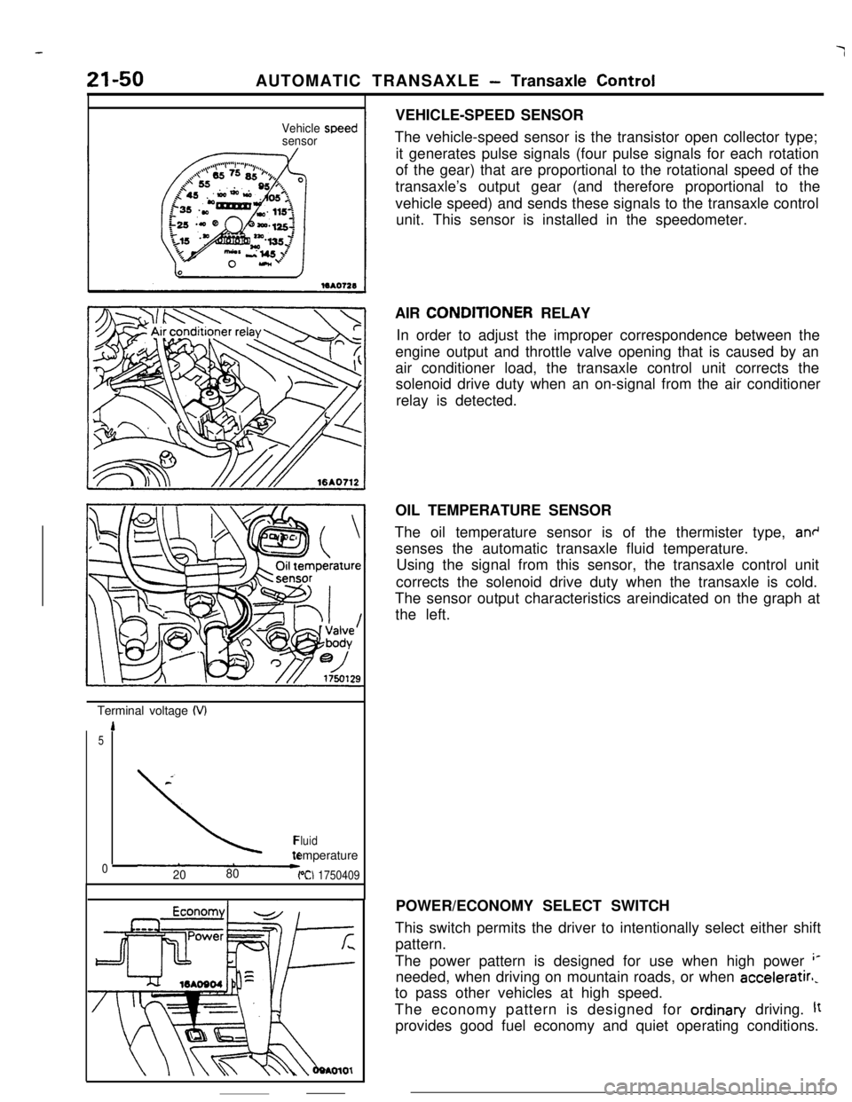
02080PCI 1750409VEHICLE-SPEED SENSOR
The vehicle-speed sensor is the transistor open collector type;
it generates pulse signals (four pulse signals for each rotation
of the gear) that are proportional to the rotational speed of the
transaxle’s output gear (and therefore proportional to the
vehicle speed) and sends these signals to the transaxle control
unit. This sensor is installed in the speedometer.
AIR CONDlTlONER RELAY
In order to adjust the improper correspondence between the
engine output and throttle valve opening that is caused by an
air conditioner load, the transaxle control unit corrects the
solenoid drive duty when an on-signal from the air conditioner
relay is detected.
OIL TEMPERATURE SENSOR
The oil temperature sensor is of the thermister type,
an+senses the automatic transaxle fluid temperature.
Using the signal from this sensor, the transaxle control unit
corrects the solenoid drive duty when the transaxle is cold.
The sensor output characteristics areindicated on the graph at
the left.
POWER/ECONOMY SELECT SWITCH
This switch permits the driver to intentionally select either shift
pattern.
The power pattern is designed for use when high power
‘*needed, when driving on mountain roads, or when acceleratirl,
to pass other vehicles at high speed.
The economy pattern is designed for ordinan/ driving.
ltprovides good fuel economy and quiet operating conditions.
Page 275 of 391

AUTOMATIC TRANSAXLE - Transaxle Control21-51
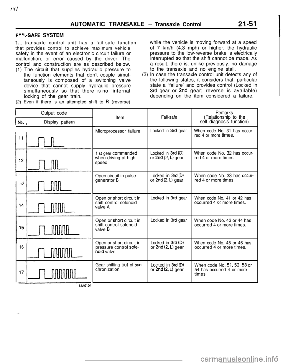
F”“.-SAFE SYSTEM7,
_ transaxle control unit has a fail-safe function
that provides control to achieve maximum vehicle
safety in the event of an electronic circuit failure or
malfunction, or error caused by the driver. The
control and construction are as described below.
(1) The circuit that supplies hydraulic pressure to
the function elements that don’t couple simul-
taneously is composed of a switching valve
device that cannot supply hydraulic pressure
simultaneouslv so that there IS no ‘internal
locking of the gear train.
(2) Even if there is an attempted shift to
Fi (reverse)while the vehicle is moving forward at a speed
of 7 km/h (4.3 mph) or higher, the hydraulic
pressure to the low-reverse brake is electrically
interrupted
SO that the shift cannot be made. Asa result, there is, unlike previously, no damage
to the transaxle and no engine stall.
(3) In case the transaxle control unit detects any of
the following states, it considers that. particular
state a “failure” and provides control (Locked in
3rd gear or 2nd gear; reverse is available)
depending on the item considered a failure.
IOutput code
r- INo.Display pattern
16
ItemFail-safeRemarks(Relationship to the
self diagnosis function)Microprocessor failure
Locked in 3rd gear
When code No. 31 has occur-
red 4 or more
times.
1 st gear commandedwhen driving at high
speedLocked in 3rd (D)or 2nd (2, L) gearWhen code No. 32 has occur-red 4 or more times.
Open circuit in pulse
generator
BLocked in 3rd (D)or 2nd (2, L) gearWhen code No. 33 has occur-red 4 or more times.
Open or short circuit in
shift control solenoid
valve A
Locked in 3rd gear
When code No. 41 or 42 hasoccurred 4 or more times.
Open or short circuit in
shift control solenoid
valve
B
Locked in 3rd gearWhen code No. 43 or 44 has
occurred 4 or more times.
Open or short circuit in
pressure control
sole-noid valve
Locked in 3rd (DIor 2nd (2, L) gearWhen code No. 45 or 46 hasoccurred 4 or more times.
Gear shifting out of syn-Locked in 3rd (D)When code No. 51,52,53 or
chronization
or 2nd (2, L) gear54 has occurred 4 or moretimes
12Ao104
-
Page 276 of 391

AUTOMATIC TRANSAXLE - Transaxle ControlSELF-DIAGNOStS SYSTEM
The transaxle control unit has self-diagnosis function.
Self-diagnosis codes can be read by connecting a voltmeter to the
diagnosis connector on the side of the junction block.
0: Ground
6%: ELC-MIT
Self-diagnosisThere are 25 diagnosis items, including those items
indicating normal conditions; a maximum of
10items can be stored in memory in the order that
they occur. The memory is supported by a power
supply directly connected to the battery so that it isretained even after the Ignition switch is turned to
the off position.
To clear the memory once an inspection has been
completed. keep negative
(-) terminal of the
battery disconnected for
10 seconds or longer.
r
No.
23
24
Output code
Display pattern
TDiagnosis itemRemarks
NormalAbnormal increases of throttle position
sensor output
Abnormal decrease of throttle position
sensor output
Poor adjustment of throttle position sen-
sorOpen circuit in oil temperature sensor
Once this occurs, output is re-
garded as 2.5 V.Once this occurs, output is re-
garded as 2.5 VOnce this occurs,
oil temperature isregarded as 80°C (176°F).
Page 277 of 391
AUTOMATIC TRANSAXLE - Transaxle Control21-53
I-.
No.-
25Output code
Diagnosis item
RemarksDisplay pattern
Open circuit or poor contact in kickdown
servo switch
IJLluuul~Short circuit in kickdown servo switch
26
-
27
-
28
u1n
CIaD; circuit in ignition pulse pickup
U1Short circuit in accelerator switch or poor
adjustment
UI12A0107
31Computer fault
Fail-safe item
uu-ln
Fail-safe item
1 st gear commanded when driving athigh speed
22
-
33
II u LnnOpen circuit in pulse generator
BFail-safe item
-
41Open circuit in shift control solenoid
valve A
Fail-safe item
nShort circuit in shift control solenoid
valve A
Fail-safe item
42
-
43
UUULMOpen circuit in shift control solenoid
valve
B
Fail-safe item
UULJMShort circuit in shift control solenoid
valve
BFail-safe item
u II II LJM12A0105
Page 278 of 391
-21-54AUTOMATIC TRANSAXLE
- Transaxle Control
Output code
Diagnosis item
Remarks
JO.Display pattern
Open circuit in pressure control solenoid
Fail-safe item
a5 nnnn valveShort circuit in pressure control solenoid
Fail-safe item
46 m valve12A0105Damaged or disconnected wiring of theDuty control is stopped after
47 nnru7_nnnnnnndamper clutch control solenoid valvegeneration.
Short-circuit of the damper clutch controlDuty control is stopped after
48 m solenord valvegeneration.
Malfunction of the damper clutch controlDuty control is stopped after
49 J- systemgeneration.
1 st gear out of synchronizationFail-safe item
51n
2nd gear out of synchronizationFail-safe iteml52n
3rd gear out of synchronizationFail-safe item
53 m4th gear out of synchronization
Fail-safe item
54
uuum12Ao106
Page 279 of 391
AUTOMATIC TRANSAXLE - Transaxle Control21-55HYDRAULIC CONTROL SYSTEM
Reaction shaft
support
BushingThe hydraulic control system consists of an oil pump which
generates hydraulic pressure for the system, and valves and
solenoid valves to control the pressure or switch the oil
passages. The valves and solenoid valves are all built in the
valve body.
OIL PUMPOil pump generates the pressure for supplying oil to the torque
converter, for lubricating frictional parts of the planetary gear
set and the overrunning clutch, etc., and for activating the
hydraulic control system.
The pump is of the inner-teeth engaging involute gear type. It
always generates the oil pressure when the engine is running
since the drive gear
is driven by 2 pawls of the pump drive hub
welded at the center of the torque converter shell.
Page 280 of 391

-
!-I
I!I
21-56AUTOMATIC TRANSAXLE - Transaxle Control~-REGULATOR VALVE
To torque convener
control valve
t
Toshift control valve,
pressure control valve
and N-D control valve(in “D”. ”2” or “L” range)
“D”.“2” or “L” range)
Oil filter
I1
To N-R control valve(in “R” range)Line relief valve
Oil pan
l
1750076
! To torque convener
IL‘I:control valve
Line pressure Pump
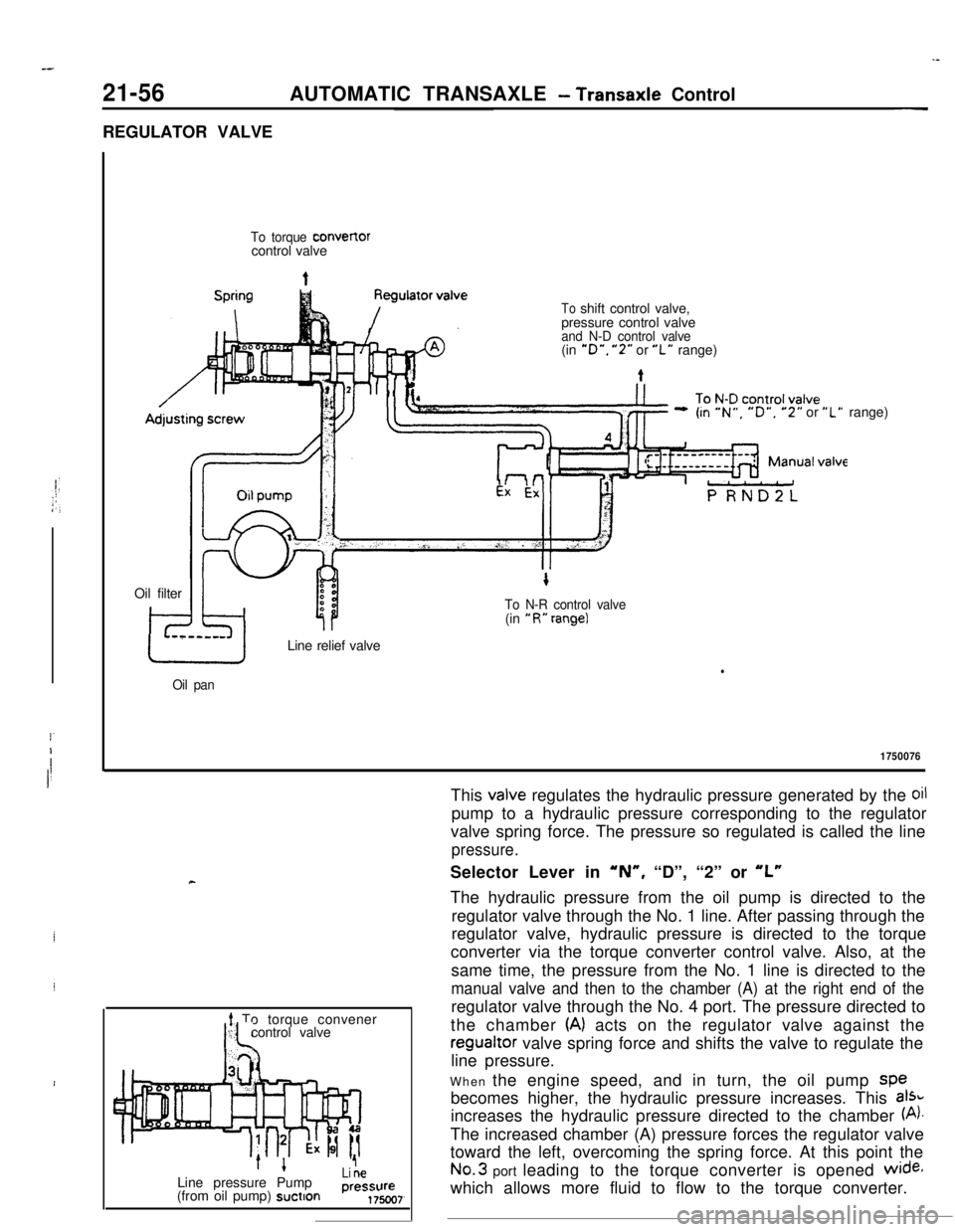
Li Ae(from oil pump) suctionprest$$)7,This
valve regulates the hydraulic pressure generated by the oilpump to a hydraulic pressure corresponding to the regulator
valve spring force. The pressure so regulated is called the line
pressure.Selector Lever in
‘N”, “D”, “2” or “L”The hydraulic pressure from the oil pump is directed to the
regulator valve through the No. 1 line. After passing through the
regulator valve, hydraulic pressure is directed to the torque
converter via the torque converter control valve. Also, at the
same time, the pressure from the No. 1 line is directed to the
manual valve and then to the chamber (A) at the right end of theregulator valve through the No. 4 port. The pressure directed to
the chamber
(A) acts on the regulator valve against theregualtor valve spring force and shifts the valve to regulate the
line pressure.
When the engine speed, and in turn, the oil pump spe
becomes higher, the hydraulic pressure increases. This
aI%increases the hydraulic pressure directed to the chamber
(A).The increased chamber (A) pressure forces the regulator valve
toward the left, overcoming the spring force. At this point theNo.3 port leading to the torque converter is opened
wide+which allows more fluid to flow to the torque converter.