Page 369 of 391

--
24-6HEATERS AND AIR CONDITIONING - Heater Construction
RELATIONSHIP BETWEEN THE DAMPER POSITION AND THE AIR-SELECTION LEVER, MOD:
SELECTION KNOB AND TEMPERATURE CONTROL KNOB
SETlINt%Air-selection Lever
LeverpositionDamperpositionOperation
When the air-selection lever
is placed in the illustrated mark position, the
air-selection damper closes the inside air inlet (air from the vehicle interior) and
opens the outside air inlet (air from the from
deck).When the air-selection lever is placed in the illustrated mark position, the
air-selection damper closes the outside air inlet and opens the
inslde atr inlet
(air from the vehicle interior).Mode-selection Knob
Knob position
(FACE:Large volume-air)
FOOT:-arge volume air)Damper position and air
flow direction
Recircu-
lation airOutside air
FACE
I): Large volume air --t: Small volume air
20A0242
Recircu-
lation airOutside air
FACE
-- FOOT2040243
Recircu-
lation air
FACE
FOOT
Recircu-lation air
FOOT
20A0245Air outflow locations
Page 370 of 391

HEATERS AND AIR CONDITIONING - Heater Construction24-7
IKnob posltionDamper position and air flow direction
Air outflow locations
Outside air
Recircu-lation air
2010246
Recircu-iation airDEF
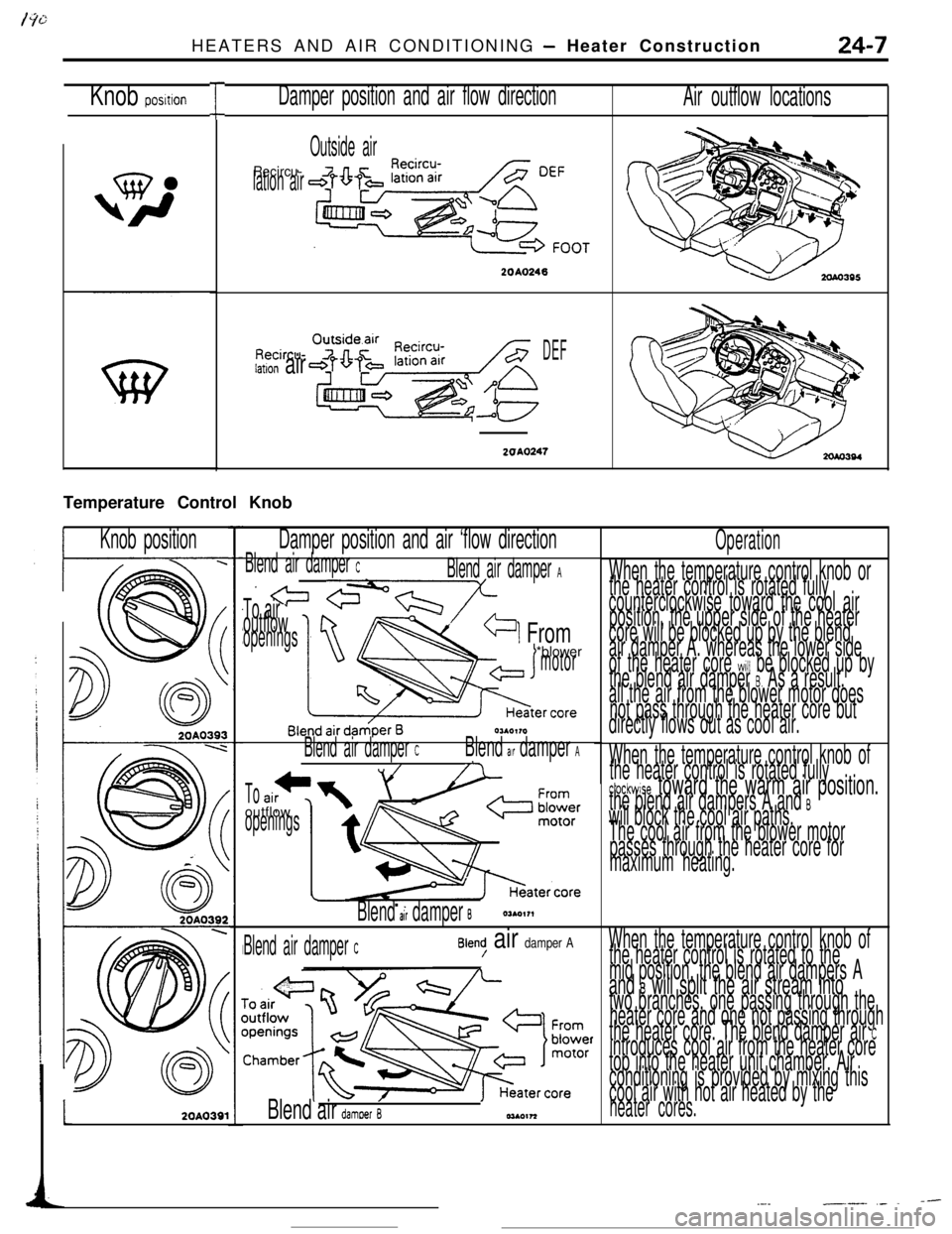
2OAO247Temperature Control Knob
IKnob positionDamper position and air ‘flow directionOperation
When the temperature control knob or
the heater control is rotated fully
counterclockwise toward the cool air
position, the upper side of the heater
core will be blocked up by the blend
air damper A. whereas the lower side
of the heater core
will be blocked up by
the blend air damper 8. As a result.
all the air from the blower motor does
not pass through the heater core but
directly flows out as cool air.
Blend air damper CBlend air damper A
x!= cY?l-nY-/
-1 From
To air Voutflowopenings*blower
motor
Hester ‘OreOUO,,O
Blend air damper CBlend air damper A,//7When the temperature control knob of
the heater control is rotated fully
ctockwise toward the warm air position.the blend air dampers A and Bwill block the cool air paths.
The cool air from the blower motor
passes through the heater core for
maximum heating..
Tooutflow
openings
Blend al’r damper B
When the temperature control knob of
the heater control is rotated to the
mid position, the blend air dampers A
and B will split the air stream intotwo branches, one passing through the
heater core and one not passing through
the heater core. The blend damper air
Cintroduces cool air from the heater core
top into the heater unit chamber. Air
conditioning is provided by mixing this
cool air with hot air heated by the
heater cores.
Blend air damper CBlend/ air damper AL
2OAO391Blend air damoer B
--.-__.__ ,_ .
Page 371 of 391
-.-- ----_-
24-8HEATERS AND AIR CONDITIONING - Compressor
COMPRESSORR24GbCOMPRESSOR CONTROL
When both the blower switch and air conditioner
switch are ON, ON-OFF control of the magnetic
clutch is accomplished by the auto compressorcontrol unit. dual pressure switch, engine coolant
temperature switch and
MPI control unit.
Sub fusible
link
Dedicatedfuse
Air conditioner
compressor relayrOFfCompressor
magnetic clutch
q l
Fusible link
lgnitionsyhWqb 1Auto compressor control unit
ITT1 I
0 bIAirAir
inlettherm0
4sensorsensor
Engine coolanttemperature switch
Enginecontrol unit13A0167
Page 372 of 391
19/---..-_HEATERS AND AIR CONDITIONING
- Idle Speed Control24-9
Ii” E SPEED CONTROL
1.increasing idle speed to withstand air condition-
er load
When the compressor is placed in the ON state
with the engine at idle, the idling speed of the
engine will be increased by approx. 150 rpm to
prevent generation of vibration and also to
prevent the engine from stalling.-
2.The stepper motor types of actuators is used for
increasing the idle speed.
IDLE SOPEED CONTROL CIRCUITFusible link
Dedicatedfuse
Air
condi-tioner
compressor relay
I-gcfc
Lll
Compre:Ignition
switch
Sub fusible
linkswitch
Auto compressor
As
mlef kr Ihemo
Ax;,: engine control unit
Idle speed control
Y *e:Q
1
$4.1111.Pk+F)rmagneticIJ
clutchEngine controlunit13AO167
Page 373 of 391

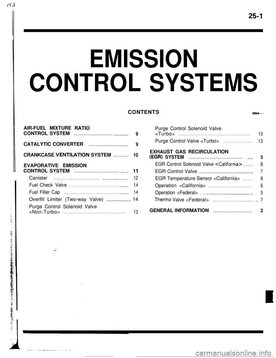
25-1
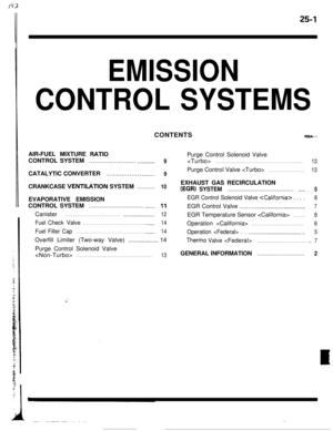
EMISSION
CONTROL SYSTEMSCONTENTS
RZSA---AIR-FUEL MIXTURE
RATIOCONTROL SYSTEM
. . . . . . . . . . . . . . . . . . . . . . . . .._.................9CATALYTIC CONVERTER
. . . . . . . . . . . . . . . . . .._............9CRANKCASE VENTlLATlON SYSTEM
. . . . . . . . . . . .10EVAPORATIVE EMISSION
CONTROL SYSTEM
: . . . . . . . . . . . . . . . . . . . . . . . . . . . . . . . ..-.........11Canister
. . . . . . . . . . . . . . . . . . . . . . . . . . . ..~...................._._...__..12
FuelCheck Valve. . . . . . . . . . . . . . . . . . . . . . . . . . . . . . . . . . . . .._.........14
FuelFiller Cap. . . . . . . . . . . . . . . . . . . . . . . . . . . . . . . . . . . . . . . . ..__....._..14Overfill Limiter (Two-way Valve)
_................... 14
Purge Control Solenoid Valve
. . . . . . . . . . . . . . . . . . . . . . . . . . . . . . . . . . . . . . . . . . . . . . . . . . . .13Purge Control Solenoid Valve
. . . . . . . . . . . _ . . . . . . . . . . . . . . . . . . . . . . . . . . . . . . . . . . . . . . . . . . . . . . . .13Purge Control Valve
. . . . . . . . . . . . . . . . . . . . . . . .13EXHAUST GAS RECIRCULATION
(EGR) SYSTEM. . . . . . . . . . . . . . . . . . . . . . . . . . . . . . . . . . . . . . . . . . . ..-......5
EGR Control Solenoid Valve . . . .8EGR Control Valve
..,.........................................7EGR Temperature Sensor
. . . . . . . .8Operation
. . . . . . . . . . . . . . . . . . . . . . . . . . . . . . . . . . . .6
Operation . . .._.........................._.._... _.5
Therm0 Valve. . . . . . . . . . . . . . . . . . . . . . . . . . . . . . . . .._.7GENERAL INFORMATION
. . . . . . . . . . . . . . . . . . . . . . . . . . . . . . . .2
Page 374 of 391

25-2EMISSION CONTROL SYSTEMS - General Information
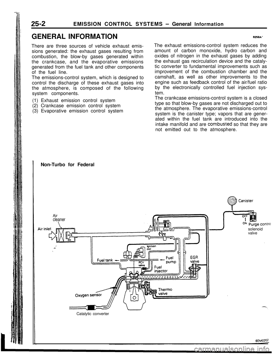
GENERAL INFORMATION
There are three sources of vehicle exhaust emis-
sions generated: the exhaust gases resulting from
combustion, the blow-by gases generated within
the crankcase, and the evaporative emissions
generated from the fuel tank and other components
of the fuel line.
The emissions-control system, which is designed to
control the discharge of these exhaust gases into
the atmosphere, is composed of the following
system components.
(1) Exhaust emission control system
(2) Crankcase emission control system
(3) Evaporative emission control system
R258A’The exhaust emissions-control system reduces the
amount of carbon monoxide, hydro carbon and
oxides of nitrogen in the exhaust gases by adding
the exhaust gas recirculation device and the cataly-
tic converter to fundamental improvements such as
improvement of the combustion chamber and the
camshaft, as well as other improvements to the
engine such as feedback control of the air/fuel ratio
by the electronically controlled fuel injection sys-
tem.
The crankcase emissions-control system is a closed
type so that blow-by gases are not discharged out to
the atmosphere. The evaporative emissions-control
system is the canister type; vapors that are gener-
ated within the fuel tank are introduced into the
intake manifold and are combusted so that they are
not emitted out to the atmosphere.
Non-Turbo for Federal
Air
cleaner
\solenoid
valve
Catalytic converter
:
0
$2:) Canister:.:
Page 375 of 391

25-1
Eh/llSSlON
CONTROL SYSTEMS
rps*---
AIR-FUEL MIXTURE RATIO
_ . . . . . . . . . . . . . . . . . . . . . . . . . . . . . . . . . . .
CATALYTIC CONVERTER . . . . . . . . . . . . . . . . . . . . . . . . . . . . . . . .
._ _.__.____.
EVAPORATIVE EMISSION
: . . . . . . . . . . . . . . .._............. _ _.I.........
Canister . . . . . . . . . . . . . . . . . . . . . . . . . . . . . . . . . . . . \
. . . . . . . . . . . . . . . . . . . ..-..
Fuel Check Valve . . .._......._....._......__...._.__.............
Fuel Filler CapI.........._........................................
Overfill Limiter (Two-way Valve)_......._._.._._....
Purge Control Solenoid Valve
.._. _...
9
_..._............................................... 5
EGR Control Solenoid Valve . . . . 8
EGR Control Valve . . . . . . . . . . . . . . .._........................... 7
EGR Temperature Sensor . . . . . . . . 8
.._................ 6
Operation . . . . . . . .._._..................._..__.__. 5
Therm0 Valv e. . . . . . . . . . . . . . . . . . . . . . . . . . . . . . . . .._. 7
GENERAL INFORMATIO N. . . . . . . . . . . . . . . . . . . . . . . . . . . . . . . . 2
Page 376 of 391

--.
25-2EMISSION CONTROL SYSTEMS - General Information
GENERAL INFORMATION
There are three sources of vehicle exhaust emis-
sions generated: the exhaust gases resulting from
combustion, the blow-by gases generated within
the crankcase, and the evaporative emissions
generated from the fuel tank and other components
of the fuel line.
The emissions-control system, which is designed to
control the discharge of these exhaust gases into
the atmosphere,is composed of the following
system components.
(1) Exhaust emission control system
(2) Crankcase emission control system
(3) Evaporative emission control system
RZSBAThe exhaust emissions-control system reduces the
amount of carbon monoxide, hydro carbon and
oxides of nitrogen in the exhaust gases by adding
the exhaust gas recirculation device and the cataly-
tic converter to fundamental improvements such as
improvement of the combustion chamber and the
camshaft, as well as other improvements to the
engine such as feedback control of the air/fuel ratio
by the electronically controlled fuel injection sys-
tem.
The crankcase emissions-control system is a closed
type so that blow-by gases are not discharged out to
the atmosphere. The evaporative emissions-control
system is the canister type; vapors that are gener-
ated within the fuel tank are introduced into the
intake manifold and are combusted so that they are
not emitted out to the atmosphere.
Non-Turbo for Federal
.;. :
0
.%??? CanisterAir
cleaner
\valveOxygenFuel tank
-a I”’ ,T
sensr’
Catalytic converter
6EMO?O2