Page 217 of 391
19-8POWER STEERING -Pinion and Valve Assembly Construction
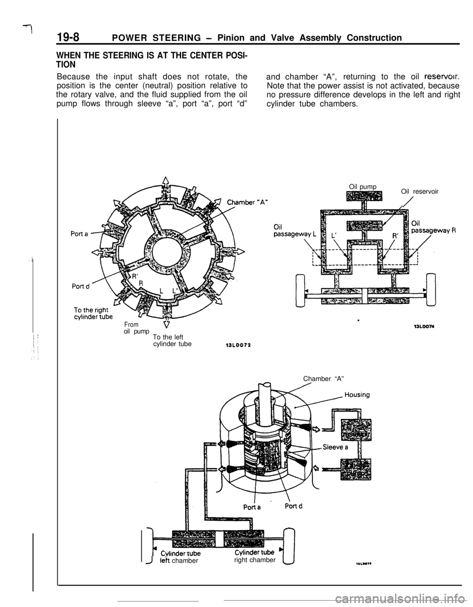
WHEN THE STEERING IS AT THE CENTER POSI-
TIONBecause the input shaft does not rotate, the
and chamber “A”,returning to the oil reservoir.
position is the center (neutral) position relative to
Note that the power assist is not activated, because
the rotary valve, and the fluid supplied from the oil
no pressure difference develops in the left and right
pump flows through sleeve “a”, port “a”, port “d”
cylinder tube chambers.
Fromoil pumpVTo the left
cylinder tubeOil pump
Oil reservoir
/
13L0072Chamber “A”
JI& chamberright chamber
Page 218 of 391

POWER STEERING -Pinion and Valve Assembly Construction
WHEN THE STEERING WHEEL IS TURNED TO
THE LEFT
IS-9
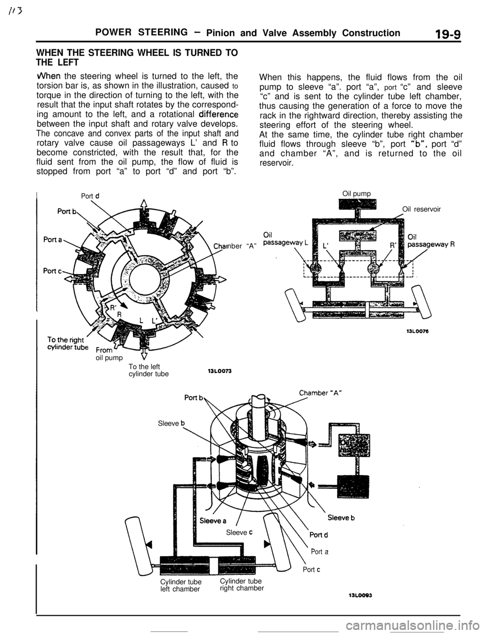
JVhen the steering wheel is turned to the left, the
torsion bar is, as shown in the illustration, caused to
torque in the direction of turning to the left, with the
result that the input shaft rotates by the correspond-
ing amount to the left, and a rotational
diff.erencebetween the input shaft and rotary valve develops.
The concave and convex parts of the input shaft androtary valve cause oil passageways L’ and
R to
become constricted, with the result that, for the
fluid sent from the oil pump, the flow of fluid is
stopped from port “a” to port “d” and port “b”.
IPort dnber “A”
SleeveWhen this happens, the fluid flows from the oil
pump to sleeve “a”. port “a”, port “c” and sleeve
“c” and is sent to the cylinder tube left chamber,
thus causing the generation of a force to move the
rack in the rightward direction, thereby assisting the
steering effort of the steering wheel.
At the same time, the cylinder tube right chamber
fluid flows through sleeve “b”, port
“b”, port “d”
and chamber “A”, and is returned to the oil
reservoir.Oil pump
Oil reservoir
Cylinder tube
left chamberCylinder tube
right chamber
\
Port a
Port cSleeve
coil pump
VTo the left
cylinder tube
13L0073
Page 219 of 391

POWER STEERING - Oil Pump13A0067
Insi
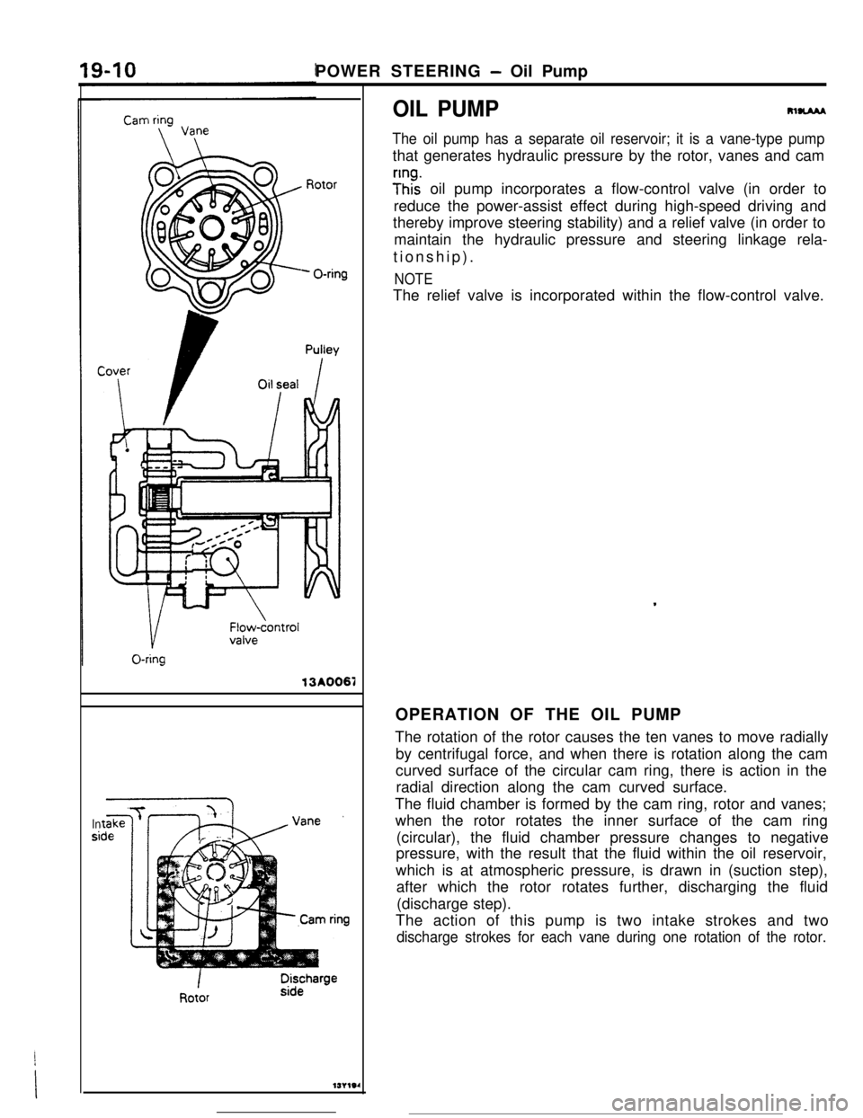
OIL PUMPRlUAM
The oil pump has a separate oil reservoir; it is a vane-type pumpthat generates hydraulic pressure by the rotor, vanes and cam
y”ht oil pump incorporates a flow-control valve (in order to
reduce the power-assist effect during high-speed driving and
thereby improve steering stability) and a relief valve (in order to
maintain the hydraulic pressure and steering linkage rela-
tionship).
NOTEThe relief valve is incorporated within the flow-control valve.
OPERATION OF THE OIL PUMP
The rotation of the rotor causes the ten vanes to move radially
by centrifugal force, and when there is rotation along the cam
curved surface of the circular cam ring, there is action in the
radial direction along the cam curved surface.
The fluid chamber is formed by the cam ring, rotor and vanes;
when the rotor rotates the inner surface of the cam ring
(circular), the fluid chamber pressure changes to negative
pressure, with the result that the fluid within the oil reservoir,
which is at atmospheric pressure, is drawn in (suction step),
after which the rotor rotates further, discharging the fluid
(discharge step).
The action of this pump is two intake strokes and
two
discharge strokes for each vane during one rotation of the rotor.
Page 220 of 391

POWER STEERING- Pinion and Valve Assembly Construction19-9
WHEN THE STEERING WHEEL IS TURNED TO
THE LEFT
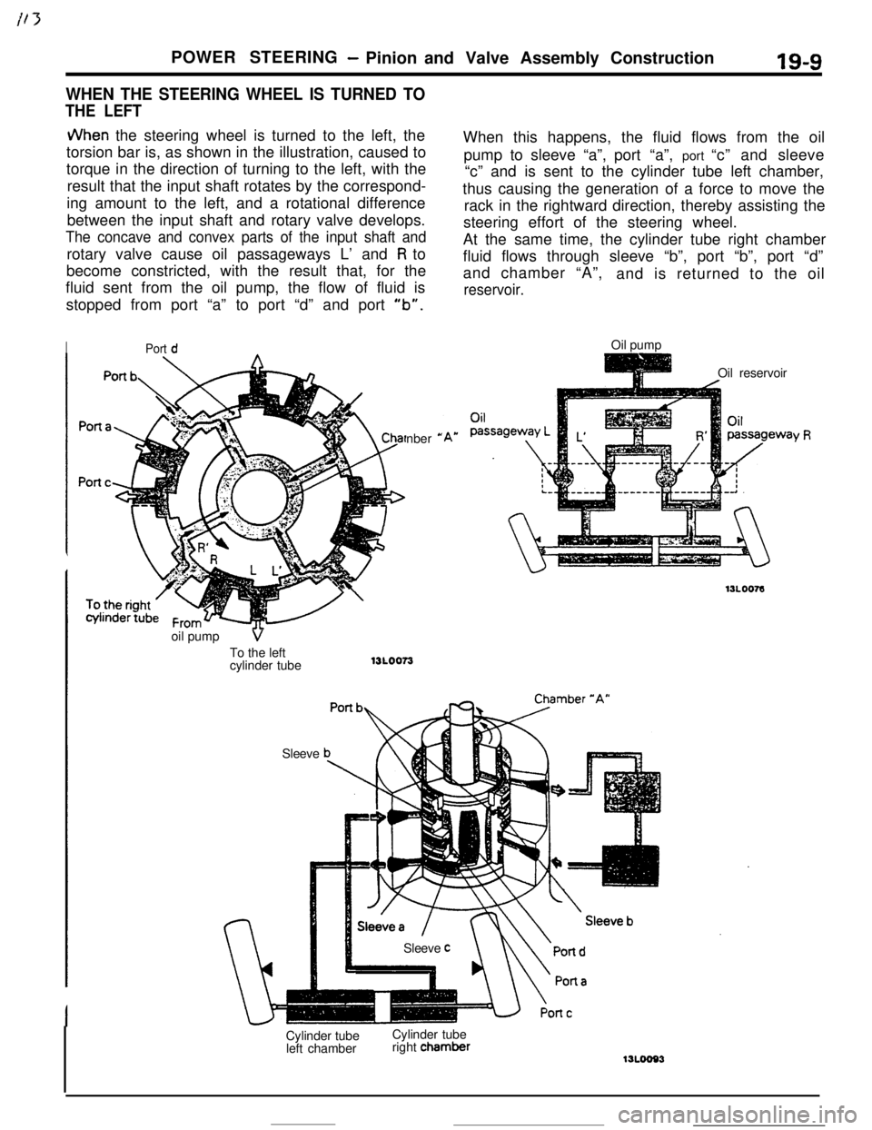
JVhen the steering wheel is turned to the left, the
torsion bar is, as shown in the illustration, caused to
torque in the direction of turning to the left, with the
result that the input shaft rotates by the correspond-
ing amount to the left, and a rotational difference
between the input shaft and rotary valve develops.
The concave and convex parts of the input shaft androtary valve cause oil passageways L’ and
R to
become constricted, with the result that, for the
fluid sent from the oil pump, the flow of fluid is
stopped from port “a” to port “d” and port
“b”.
IPort dnber
*oil pump
VTo the left
cylinder tube13LOO73
SleeveWhen this happens, the fluid flows from the oil
pump to sleeve “a”,port “a”, port “c” and sleeve
“c” and is sent to the cylinder tube left chamber,
thus causing the generation of a force to move the
rack in the rightward direction, thereby assisting the
steering effort of the steering wheel.
At the same time, the cylinder tube right chamber
fluid flows through sleeve “b”, port “b”, port “d”
and chamber “A”,
and is returned to the oil
reservoir.Oil pump
Oil reservoir
Sleeve
cCylinder tube
left chamberCylinder tube
right chamber
‘Y R
Page 221 of 391

POWER STEERING - Oil Pump
OIL PUMP13A0067
Insi
m-
The oil pump has a separate oil reservoir; it is a vane-type pumpthat generates hydraulic pressure by the rotor, vanes and cam
;Inhz oil pump incorporates a flow-control valve (in order to
reduce the power-assist effect during high-speed driving and
thereby improve steering stability) and a relief valve (in order to
maintain the hydraulic pressure and steering linkage rela-
tionship).
NOTEThe relief valve is incorporated within the flow-control valve.
.OPERATION OF THE OIL PUMP
The rotation of the rotor causes the ten vanes to move radially
by centrifugal force, and when there is rotation along the cam
curved surface of the circular cam ring, there is action in the
radial direction along the cam curved surface.
The fluid chamber is formed by the cam ring, rotor and vanes;
when the rotor rotates the inner surface of the cam ring
(circular), the fluid chamber pressure changes to negative
pressure, with the result that the fluid within the oil reservoir,
which is at atmospheric pressure, is drawn in (suction step),
after which the rotor rotates further, discharging the fluid
(discharge step).
The action of this pump is two intake strokes and two
discharge strokes for each vane during one rotation of the rotor.
Page 222 of 391
POWER STEERING - Oil Pump
PERFORMANCE OF THE OIL PUMP
(1)
19-11 i
P-Qf characteristic (pump pressure vs. discharge quantity)
At pump rotation of 600 rpm and fluid temperature of
50-6O”C (122-l 40°F):4.4
litmin. (268.5 cu.in./min.), or more at pump pressure of
4,000
kPa (569 psi)
N-Qf Characteristic (pump rpm vs. discharge quantity)
At pump pressureof 2,000
kPa (285 psi) and fluid
temperature of
50-60X (122-140°F):
6.58
lit./min. (396.7-488.2 cu.in./min.) at pump rotation of
1,500 rpm.
3.8-6 lit./min. (231.9-366.1 cu.in./min.) at pump rotation of
3,000 rpm.
2.5-3.5 Mnin. (152.6-213.6 cu.in./min.) at pump rotation
of 4,500 rpm.
OPERATION OF THE FLUID
FLOW-
r7NTROL SYSTEM
I t 13 plunger and flow-control valve are activated bythe oil pump, thus regulating the amount of fluid
the hydraulic pressure of the fluid discharged fromflow to the gear box.
Pl;lgRelief ipring\
Relief valve13POO37
Page 223 of 391

19-12POWER STEERING - Oil Pump
WHEN OIL PUMP OPERATES AT LOW SPEED
(70&l ,000 RPM)
A part of the fluid discharged from the oil pumpvariable orifices. As a result of this action the fluid
passes through the pilot port and hydraulic pressurepasses through the variable and fixed orifices, and is
is applied to the rear surface of the plunger, but,sent, by way of the plunger, to the gear box. The
because this hydraulic pressure is weak, the plungeramount of discharge to the gear box at this time is
is pushed toward the left as a result of the forcealmost maximum, with the result that an extremely
applied by the plunger’s spring, thus opening thelow steering effort is required.
PlungerVariable orificeFixed,orificeFioycontrol valve
/ I
From oil pump
To oil pumpVariable orifice
13POO38-.
Pilot portFixed orifice
.WHEN OIL PUMP OPERATES AT MEDIUM
SPEED
(1 ,OOm,OOO RPM)
When the engine speed increases and the pump’ssame time, the flow-control valve also is pressed
speed also increases, the hydraulic pressure of thetoward the
right, the bypass port opens more, and
fluid discharged from the pump becomes higher,the surplus fluid is returned back to the oil pump. In
overcoming the plunger spring’s force, and causingthis way, the amount of discharge flow to the gear
the plunger to move toward the right. As a result ofbox is reduced, thus resulting in a somewhat
this action, one of the variable orifices closes. At the“heavier” steering effort.
Variable orifice
PlungerFlow-control valve
\\Fixed yrifice/
Variable &iflceBypass ‘LrllJPOO59
Page 224 of 391

i t-7POWER STEERING
- Oil Pump19-13WHEN OIL PUMP OPERATES AT HIGH SPEED
(? -70 RPM OR MORE)
VII, ,dn the pump operation becomes high speed. thethe gear box then is supplied only from the fixed
plunger is pushed further toward the
right than fororifice, with the result that the amount of discharge
medium speed, and both variable orifices close.flow
is reduced to minimum, and, as a result, theFurthermore. the flow-control valve also moves, and
steering effort becomes moderately “heavy”, thus
the bypass port opens wider. The fluid flowing to
providing excellent handling stability at high speed.
Fixed orifice13POO40
OPERATION OF THE RELIEF VALVE
When the A chamber pressure increases when theAs a result of this action, the pressure of the
Bsteering wheel is turned while the vehicle ischamber decreases, and the relief valve closes once
stopped, the
B chamber pressure also increases.again. This action takes place in a moment, and in
and, when the pressure exceeds the relief springthis way, by maintaining the correct balance, the
set load of 8,000 kPa (1,138 psi), the relief valve panmaximum pressure is controlled.
which is closed by a steel ball opens and the fluid
passes through the bypass port and is returned to
the pump’s intake port.
Steel ballRelief sprtngTo steering gear box
/Bypass pan
WPOO41