Page 169 of 391

FUEL SYSTEMAir Flow Sensor (AFSI Filter Reset Control /- Turbo Meter Control 14-57
AIR FLOW SENSOR (AFS) FILTER RESET CONTROL Engine control unit
I1Air flow sensor
Crank-angle sensorIdle position switch
Throttle position sensor
4Air flow sensor
//\\ -
\Reset terminal
RllruAs
6FlJo664I11When the idle switch is ON, or when the throttleWhen these Signals are input. the air flow sensor
position sensor output voltage is low, the engineresets the modulator. There is a switch to the circuit
control unit functions to switch ON the powerthat lessens turbo noise. This eliminates any error in
transistor, and, as a result, air flow sensor resetmeasuring the
.amount of intake air when there is a
signals are sent to the air flow sensor.change from high speed, high load driving to
deceleration.
TURBO METER CONTROL
Air flow sensor
(AFSI ’
Crank angle sensorEngine control unit
BT
Rl4QAAATurbo meterControl relay
The turbo meter is a current type meter. The engine
control unit receives the intake air volume signal
from the air flow sensor and the rpm
signal from the
crank angle sensor and calculates the engine load.Then, the unit determines the duty ratio according
to the load and drives the turbo meter.
Intake air volume
Duty ratio
it Load 0:rwDuty ratio
The duty ratio is defined as ON time ratio
TJT, of 33.3 Hz pulse.
When the duty ratio increases, average current that flows to
the turbo meter also increases
so that the turbo meter
indicates higher value.
When the duty ratio is decreased, the turbo meter indicates
smaller value.
cI30
msec. 30 msec.1621cm:
Page 170 of 391
._ ..-
14-58
.-FUEL SYSTEM
- Accelerator Components
-7
ACCELERATOR COMPONENTSRlUUAAThe accelerator is the cable type, and the pedal is
the suspended type.
A nylon bushing is installed on the end of the
accelerator cable, preventing contact noise
be-tween the cable and accelerator arm from beinggenerated.
In addition, the accelerator pedal switch, which is
used as a control sensor on models with the4-speed NT, is equipped at the pedal support
member.
CONSTRUCTION DIAGRAM
Accelerator cable
Accelerator pedal
switch
bushing
\Accelerator
cableAccelerator
ahmember
Accelerator
Accelerator
pedal
Page 171 of 391
FUEL SYSTEM -Auto-cruise Control System14-59AUTO-CRUISE CONTROL SYSTEMRIIPA&A
using the auto-cruise control system, the vehicle
oar-rbe maintained at a constant driving speed
[between 40 km/h (25 mph) or higher and 145 km
(90 mph) or lower], as selected by the driver,
without using the accelerator pedal.The actuator is the DC motor-driven type for a high
degree of adherence to the set speed. A flexiblesupport system is used for installation of the
actuator in order to prevent the transaxle of body
vibrations to the actuator.
CONSTRUCTION DIAGRAM
control switchOJAO2SS
Accelerator
Actuator
ab’ea\ A
Inhibitor switch
Vehicle speed sensor
(reed switch)
Accelerator cab1e.A/IClutch switch
/Accelerator pedal switch IStop light switch
Page 172 of 391
Page 173 of 391
F
FUEL SYSTEM -Auto-cruise Control System'l4-61
AUTOCRUISE CONTROL UNIT
Je auto-cruise control unit incorporates a micro-computer which provides the set coast, resume,
acceleration, cancel, low-speed limitation,
high-speed limitation, overdrive OFF control, and
auto-
matic cancellation functions. The microcomputer
inputs signals from the vehicle speed sensor and
the switches, and outputs Control signals to the
actuator’s DC motor, the electromagnetic clutch,and the automatic
.transaxle (4 A/T) control unit in
accordance with the programming (software) of themicrocomputer.
CONTROL LOGIC BLOCK DIAGRAM
--
Auto-cruise control UnitIgnitionswitcha.-.
I
Input interface circuit
piz7q.f~~
I
L
Micro-
computer
jutput interface circuitIr--lI----
--7I IActuatorI
Electromagnetic
clutch coil
OD-OFF out-
put circuit
NC: Normally closed
Page 174 of 391

14-62FUEL SYSTEM - Auto-cruise Control System
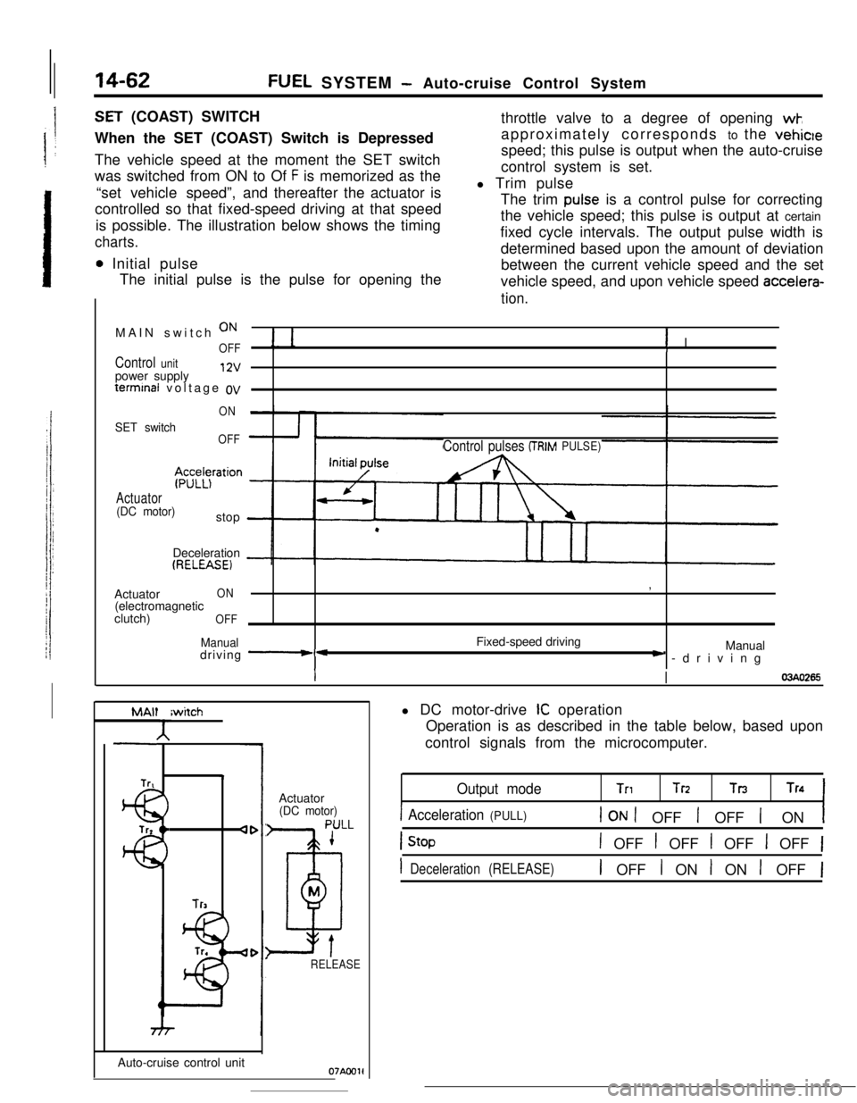
SET (COAST) SWITCH
When the SET (COAST) Switch is Depressed
The vehicle speed at the moment the SET switch
was switched from ON to Of
F is memorized as the
“set vehicle speed”,and thereafter the actuator is
controlled so that fixed-speed driving at that speed
is possible. The illustration below shows the timing
charts.
0 Initial pulse
The initial pulse is the pulse for opening thethrottle valve to a degree of opening
wk,approximately corresponds to the vehicle
speed; this pulse is output when the auto-cruise
control system is set.
l Trim pulse
The trim
pulse is a control pulse for correcting
the vehicle speed; this pulse is output at certain
fixed cycle intervals. The output pulse width is
determined based upon the amount of deviation
between the current vehicle speed and the set
vehicle speed, and upon vehicle speed
accelera-
tion.MAIN switch
ON
OFF! I
Control unitpower supply12vterminal voltage
ov
ON
SET switchOFF
$z;z$ration
Actuator(DC motor)stop
Control pulses (TRIMPULSE)Deceleration
(RELEASE)Actuator
ON(electromagnetic
clutch)
OFF
Manualdriving -*Fixed-speed driving,
Manual) -driving
II03440265
MAlt
A
Trtiwitch4
lr3Auto-cruise control unitActuator
(DC motor)
PULL
1
D
M
tRELEASE
Oi'AC01ll DC motor-drive
IC operation
Operation is as described in the table below, based upon
control signals from the microcomputer.
Output modeTnTrz TnTn
1 Acceleration (PULL)1 ON 1 OFF 1 OFF 1 ON1
1 OFF t OFF 1 OFF 1 OFF 1
1 Deceleration (RELEASE)1 OFF I ON I ON 1 OFF 1
Page 175 of 391

FUEL SYSTEM - Auto-cruise Control System14-63
FixedDecebFixed
speed -bb-Highration+ c- speed
Vehicle
speedLow
SET ON
switch
OFF
DC StoPmotor Decele-
ration(RELEASE)07LOcaWhen the SET (COAST) Switch
,is Held Down
While the SET switch is ON, the actuator’s DC motor is caused
to rotate to the
RELEASE side; the vehicle speed when the
switch is switched
OFF as deceleration continues is entered in
the memory, and is thereafter controlled as the fixed speed.
Note that the vehicle speed must be the low-speed limit
[approximately 40 km/h (25 mph)] or higher.
Vehicle speed
Cancel signalElectromagnetic
clutch
RESUME switchRESUME (ACCEL) SWITCH
When the RESUME (ACCEL) Switch is Turned after the
Auto-cruise Control has been Canceled
When (after the auto-cruise control system is canceled by the
cancel signal) the RESUME switch is switched from OFF to ON
while driving at a vehicle speed which is the low-speed limit
[approximately 40 km/h (25 mph)] or higher, the vehicle speed
memorized before cancellation of the auto-cruise control
system will be controlled as the fixed speed.
Even if the vehicle speed is at or below the low-speed limit,
there can be a return
to: the set speed (before cancellation of
the auto-cruise control system) by using the accelerator to
increase the vehicle speed to 40 km/h (25 mph) or higher and
then switching the RESUME switch from OFF to ON.
Note that
jhe set speed (before cancellation of the auto-cruise
control system) will be erased from the memory circuit of the
control unit if the MAIN switch or ignition switch is switched
from ON to OFF or the vehicle speed is decreased to 35 km/h
(22 mph) or less, and thereafter the auto-cruise control system
will not operate even if the RESUME switch is turned ON.
HighLow
18pprOX.40 knVh(25 mph) or lugharl
ON
OFFI
ON
OFF
ON
OFF1IActuatorAcceleration
(DC motor)(Pff LL) Stop
RESUME (reset)Fixed-speed control
Autocruise control system cancellation07LOOO5
Page 176 of 391
![MITSUBISHI ECLIPSE 1990 Service Manual 14-64FUEL SYSTEM - Auto-cruise Control System
FixedAccelera-FixedSpeed -c tion-LC speed
High
Vehic’e iapprox. 40 km/hspeedG!5 mph) or hagher]Low
’When the RESUME
(ACCEL) Switch is Kept Turned
Whi MITSUBISHI ECLIPSE 1990 Service Manual 14-64FUEL SYSTEM - Auto-cruise Control System
FixedAccelera-FixedSpeed -c tion-LC speed
High
Vehic’e iapprox. 40 km/hspeedG!5 mph) or hagher]Low
’When the RESUME
(ACCEL) Switch is Kept Turned
Whi](/manual-img/19/57103/w960_57103-175.png)
14-64FUEL SYSTEM - Auto-cruise Control System
FixedAccelera-FixedSpeed -c tion-LC speed
High
Vehic’e iapprox. 40 km/hspeedG!5 mph) or hagher]Low
’When the RESUME
(ACCEL) Switch is Kept Turned
While the RESUME switch is ON, the actuator’s DC
mote,caused to rotate to the PULL side; the vehicle speed when the
switch is switched OFF as acceleration continues is entered in
the memory, and is thereafter controlled as the fixed speed.
CANCELLATION
When, during fixed-speed driving, the signals described below
are input, conductivity to the electromagnetic clutch is inter-
rupted, thus
cancelling the auto-cruise control system.
l Stop light switch ON (brake pedal depressed)
l Clutch switch ON (clutch pedal depressed)
lInhibitor switch ON (selector lever at
“P” or “N” position)
LOW-SPEED LIMIT
There is automatic cancellation at or below the low-speed limit
vehicle speed [approximately 40 km/h (25 mph)].
HIGH-SPEED LIMIT
The vehicle cannot be driven at a fixed speed which is at or
higher than the high-speed limit [approximately 145 km/h
(90
mph)l.Note that the vehicle speed memorized when the SET switch
a5pressed while the vehicle is traveling at the high-speed limit or
higher
vvill be the high-speed limit vehicle speed.
FAIL-SAFE FUNCTION
When the following situations are encountered during fixed-
speed driving, the signals to interrupt, conductivity to the
electromagnetic clutch are input, thus canceling the auto-cruise
control system.
0
0
0When vehicle speed decreases to the low-speed limit
[approx. 40 km/h (25 mph)].
If the vehicle speed decreases to a speed which is
approximately 20 km/h (12 mph) or more below ‘the
memorized vehicle speed.
When the vehicle speed drops by 20 km/h
(12 mph) or more
after having reached the set speed -10 km/h (-6 mph) in
the RESUME mode.
If there is damaged or disconnected wiring of the input line
(stop light switch load side) of the stop light switch.
if there is no input of the vehicle speed signal for a certain
fixed time (1 second or longer).
If the SET and RESUME control switches are switched ON
at the same time.
If the cancel switches (stop light switch, clutch switch or
inhibitor switch) and command switches (SET switch
orRESUME switch) are switched ON at the same time.
if the actuator clutch driver (transistor) of the control unk
remains ON (short-circuit).