Page 55 of 391

ELECTRICAL - Fuses8-3q
rMULTI-PURPOSE FUSES
The multi-purpose fuses are located within the junction block at
the lower part of the instrument panel (at the driver’s seat side).
These fuses are all the blade type; 1 O-ampere, 15-ampere and
30-ampere fuses are used.
IPower supply circuitFuse No.
RatedLoad circuitapacity
(A)IBattery
t-lonition,itchBattery
IGz
ACC
IG,
10
10
10
15
15
10Automatic seatbelt control unit, buzzer, passing control relay,
key reminder switch, theft-alarm starter relay
Air conditioner control unit, air conditioner switch, heater relay,
power window relay, defogger timer, daytime running light relay
2
only>, transistor relay
RadioCigarette lighter, remote controlled mirror
Door lock relay, door lock control unitAuto-cruise control unit
, AA control unit,
inhibitor switch, combination meter
ACC
IGI9
1011
12
1315
10
10
10Wiper motor, washer motor, intermittent wiper relay
Horn, headlight relay, theft-alarm control unit, daytime running
light relay
1 Auto-cruise control unit, auto-cruise control actuator,
automatic seatbelt control unit, theft-alarm control unit,
combination meter, warning light, seatbelt timer
Turn-signal and hazard flasher u.nit
14
15
16
17
10Theft-alarm horn relay
30Blower motor
15Stop light
Back up light
CM/T>, dome light relay
!Dome light. luggage compartment
Irght, foot. Irght.door-ajar warntng light, radio, MPI control unrt.AK control unit, ignition key illumination light.security lightI
Page 56 of 391
_--
8-4ELECTRICAL - Fuses / Diagnosis System
61543
2
16R133lDEDICATED FUSES
For high-load circuits, fuses dedicated to each individual circuit
are used.
The dedicated fuses are provided in the relay box of the engine
compartment.
No.
I
Circuit
I
H,“d;;-;I
Rated
canacitv (A)I
1 1 Tail light circuitIRedI10I
2Fog light circuitRed10
3,.Hazard warning light circuitRed10
4 ) Upper beam circuitIRedI10I
5’
I
Air conditioner magnet
I
Red
I
10
clutch circuitI
6’Condenser fan motorYellow20
circuitI
NOTEl : Air conditioner equipped models.DIAGNOSIS SYSTEM
- CHECK CON-
NECTORS
nmcwaBThe connectors for diagnosis of the following systems are
provided beside the junction block.
1. Multi-point Fuel injection System
2. Automatic
Transaxle.3. Diagnosis control
z. grm.rlnaFd vehicle speed
6: Auto-cruise control
:..--.-__-.
Page 62 of 391
_--__ .-
I8-10ELECTRICAL -Relays, Control Units and Sensors
I
1AUI‘O-CRUISE CONTROL SYSTEM
ps+%JVehicle speed sensor (reed switch)
AUTOMATIC SEAT BELT
NameAutomatic seat belt control unit
‘
SymbolNameSymbol
AAutomatic seat belt motor relay
A0
Page 113 of 391
---
14-1
FUEL
RWA---
ACCELERATOR COMPONENTS
.72
Auto-cruise Control Switch
:.............. 77
Self-diagnosis and Input-check Functions
injector................................................................34
PRESSURi
CONTROL ............................................................
31
Fuel Tank............................................................i
injector................................................................
Specifications
izi
INTAKE
il
Coolant Temperature Sensor
;iI
General Description
: .................... 24
ignition Timing Adjustment Terminal ............
CA/T>.................................... 26
i:
..........
.-.---__-...- -.---.
Page 171 of 391
FUEL SYSTEM -Auto-cruise Control System14-59AUTO-CRUISE CONTROL SYSTEMRIIPA&A
using the auto-cruise control system, the vehicle
oar-rbe maintained at a constant driving speed
[between 40 km/h (25 mph) or higher and 145 km
(90 mph) or lower], as selected by the driver,
without using the accelerator pedal.The actuator is the DC motor-driven type for a high
degree of adherence to the set speed. A flexiblesupport system is used for installation of the
actuator in order to prevent the transaxle of body
vibrations to the actuator.
CONSTRUCTION DIAGRAM
control switchOJAO2SS
Accelerator
Actuator
ab’ea\ A
Inhibitor switch
Vehicle speed sensor
(reed switch)
Accelerator cab1e.A/IClutch switch
/Accelerator pedal switch IStop light switch
Page 172 of 391
Page 173 of 391
F
FUEL SYSTEM -Auto-cruise Control System'l4-61
AUTOCRUISE CONTROL UNIT
Je auto-cruise control unit incorporates a micro-computer which provides the set coast, resume,
acceleration, cancel, low-speed limitation,
high-speed limitation, overdrive OFF control, and
auto-
matic cancellation functions. The microcomputer
inputs signals from the vehicle speed sensor and
the switches, and outputs Control signals to the
actuator’s DC motor, the electromagnetic clutch,and the automatic
.transaxle (4 A/T) control unit in
accordance with the programming (software) of themicrocomputer.
CONTROL LOGIC BLOCK DIAGRAM
--
Auto-cruise control UnitIgnitionswitcha.-.
I
Input interface circuit
piz7q.f~~
I
L
Micro-
computer
jutput interface circuitIr--lI----
--7I IActuatorI
Electromagnetic
clutch coil
OD-OFF out-
put circuit
NC: Normally closed
Page 174 of 391

14-62FUEL SYSTEM - Auto-cruise Control System
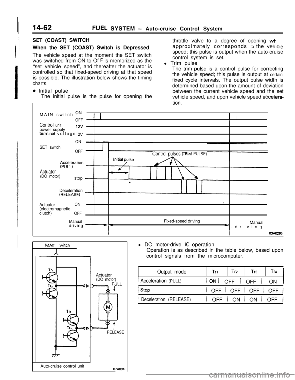
SET (COAST) SWITCH
When the SET (COAST) Switch is Depressed
The vehicle speed at the moment the SET switch
was switched from ON to Of
F is memorized as the
“set vehicle speed”,and thereafter the actuator is
controlled so that fixed-speed driving at that speed
is possible. The illustration below shows the timing
charts.
0 Initial pulse
The initial pulse is the pulse for opening thethrottle valve to a degree of opening
wk,approximately corresponds to the vehicle
speed; this pulse is output when the auto-cruise
control system is set.
l Trim pulse
The trim
pulse is a control pulse for correcting
the vehicle speed; this pulse is output at certain
fixed cycle intervals. The output pulse width is
determined based upon the amount of deviation
between the current vehicle speed and the set
vehicle speed, and upon vehicle speed
accelera-
tion.MAIN switch
ON
OFF! I
Control unitpower supply12vterminal voltage
ov
ON
SET switchOFF
$z;z$ration
Actuator(DC motor)stop
Control pulses (TRIMPULSE)Deceleration
(RELEASE)Actuator
ON(electromagnetic
clutch)
OFF
Manualdriving -*Fixed-speed driving,
Manual) -driving
II03440265
MAlt
A
Trtiwitch4
lr3Auto-cruise control unitActuator
(DC motor)
PULL
1
D
M
tRELEASE
Oi'AC01ll DC motor-drive
IC operation
Operation is as described in the table below, based upon
control signals from the microcomputer.
Output modeTnTrz TnTn
1 Acceleration (PULL)1 ON 1 OFF 1 OFF 1 ON1
1 OFF t OFF 1 OFF 1 OFF 1
1 Deceleration (RELEASE)1 OFF I ON I ON 1 OFF 1