Page 254 of 1273
13-112FUEL SYSTEM
VALVE> - Fuel Tank
03L0018
QcD ua .
CFa
cc
0c aa0u0aa
Positioning projection
03L0009
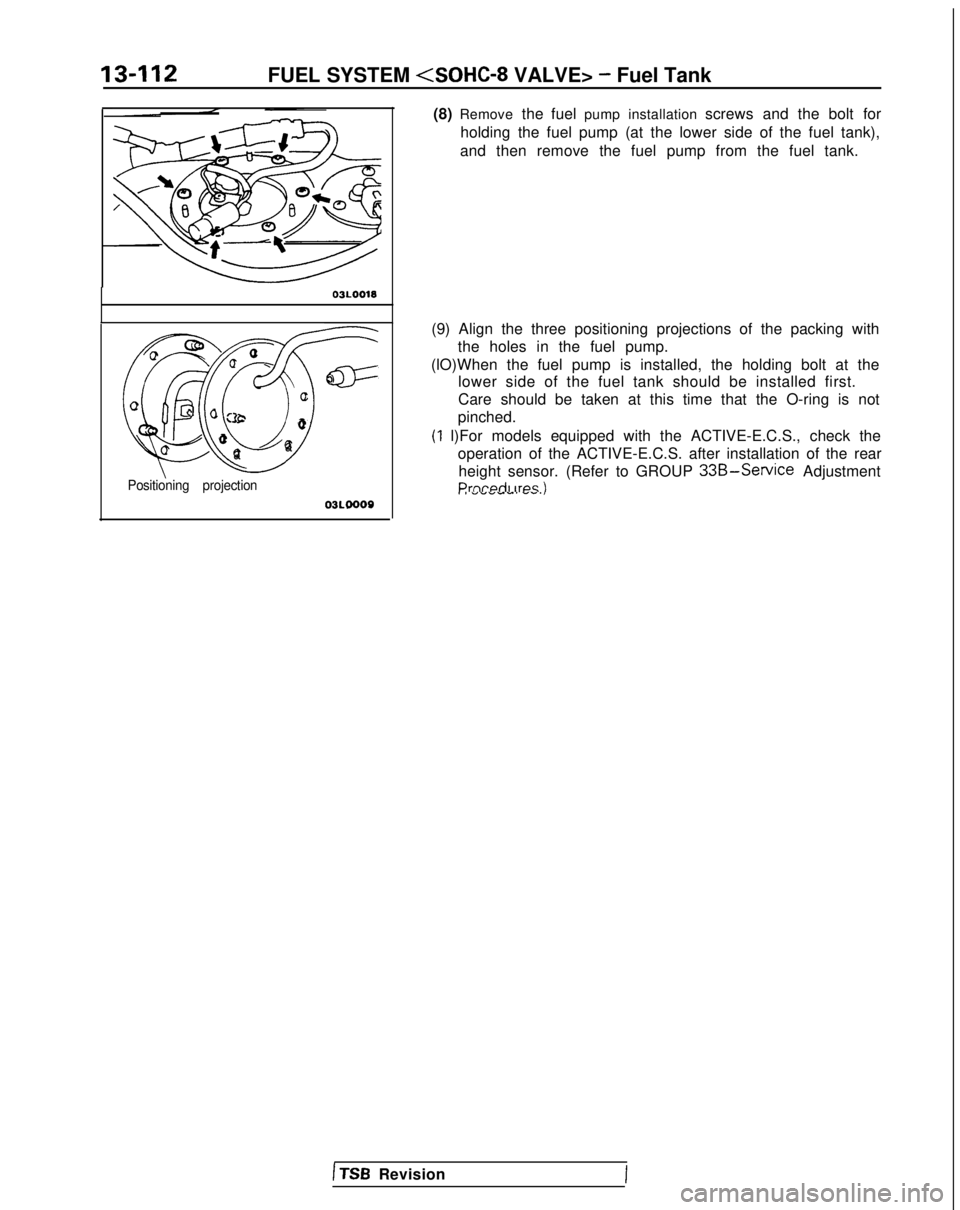
(8) Remove
the fuel pump installation screws and the bolt for
holding the fuel pump (at the lower side of the fuel tank),
and then remove the fuel pump from the fuel tank.
(9) Align the three positioning projections of the packing with the holes in the fuel pump.
(lO)When the fuel pump is installed, the holding bolt at the lower side of the fuel tank should be installed first.
Care should be taken at this time that the O-ring is not
pinched.
(1 l)For models equipped with the ACTIVE-E.C.S., check the operation of the ACTIVE-E.C.S. after installation of the rearheight sensor. (Refer to GROUP
33B-Service AdjustmentPrnrwiI irps II I ““VW-. W.S.,
1 TSB Revision
Page 257 of 1273
FUEL SYSTEM
VALVE> -Fuel Line and Vapor Line/Fuel Filter 13-115
Higt
fuel
&ring Oi’
FUEL FILTER
REMOVAL AND INSTALLATION
~zgz&i&r” 1@Release of Residual Pressure from High
2. INSTALLATION OF HIGH PRESSURE FUEL HOSE
Apply engine oil to the hose union.Insert the hose, being careful not to damage the O-ring, and
tighten securely.
Caution Because there is high pressure applied between the
fuel pump and the injection mixer, be especially sure
that there is no fuel leakage in this area.
25-35 N
m
18-25
ft.lbs.
Post-installation Operation@Measurement of Fuel Pressure
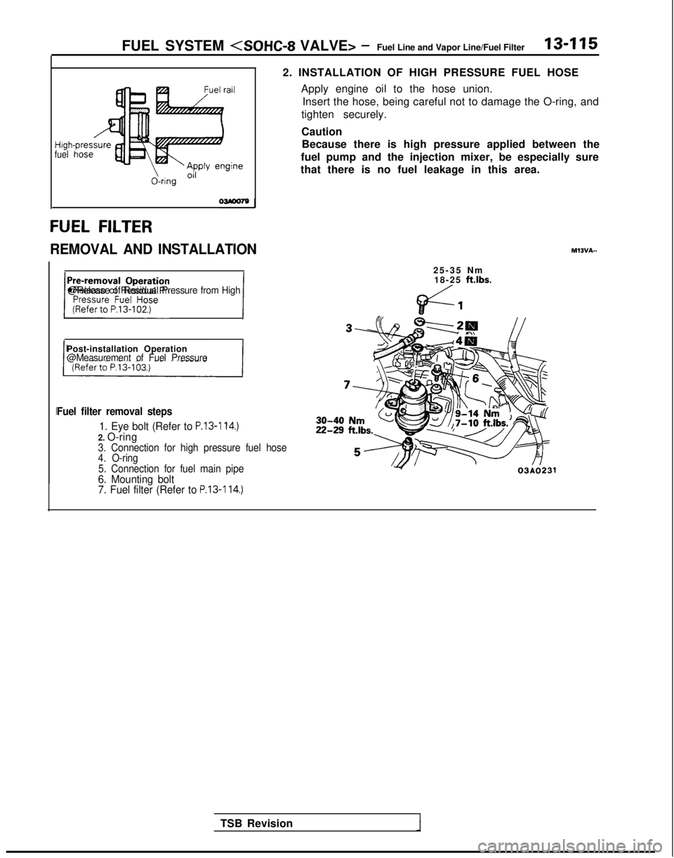
Fuel filter removal steps
1. Eye bolt (Refer to P.13-114.)2. O-ring3. Connection for high pressure fuel hose
4. O-ring
5. Connection for fuel main pipe
6. Mounting bolt
7. Fuel filter (Refer to P.13-114.)
TSB Revision 03AO231
Page 260 of 1273
13418FUEL SYSTEM (SOHC-16 VALVE> - Specifications
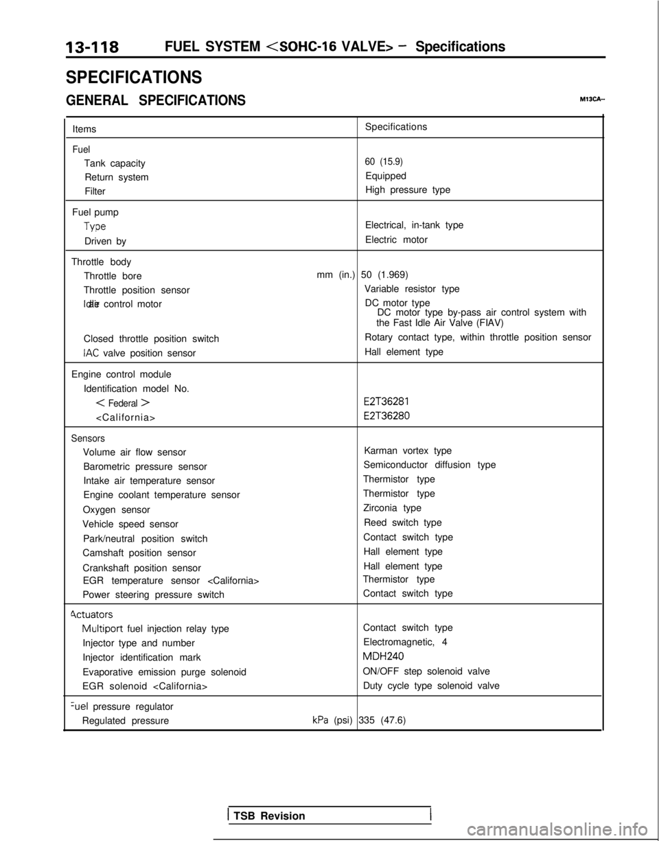
SPECIFICATIONS
GENERAL SPECIFICATIONSMISCA-
Items
Fuel
Tank capacityReturn system
Filter
Fuel pump Type
Driven by
Throttle body Throttle bore
Throttle position sensor Idle air control motor
Closed throttle position switch
IAC valve position sensor
Engine control module Identification model No.
< Federal >
Sensors
Volume air flow sensorBarometric pressure sensor
Intake air temperature sensor
Engine coolant temperature sensor
Oxygen sensor
Vehicle speed sensor
Park/neutral position switch
Camshaft position sensor
Crankshaft position sensor EGR temperature sensor
Power steering pressure switch
Cvctuators
Multiport fuel injection relay type
Injector type and number
Injector identification mark
Evaporative emission purge solenoid
EGR solenoid %el
pressure regulator
Regulated pressure Specifications
60 (15.9)
Equipped
High pressure type
Electrical, in-tank type
Electric motor
mm (in.) 50 (1.969) Variable resistor typeDC motor type DC motor type by-pass air control system with
the Fast Idle Air Valve (FIAV)
Rotary contact type, within throttle position sensor
Hall element type
E2T36281 E2T36280
Karman vortex type
Semiconductor diffusion type
Thermistor type
Thermistor type Zirconia type
Reed switch type
Contact switch type Hall element type
Hall element type
Thermistor type
Contact switch type
Contact switch type
Electromagnetic, 4 MDH240
ON/OFF step solenoid valve Duty cycle type solenoid valve
kPa (psi) 335 (47.6)
1 TSB Revision
Page 269 of 1273
Page 270 of 1273
13-128FUEL SYSTEM - Troubleshooting
CIRCUIT DIAGRAM
< 1993 models>
IGNITIONSWITCH(ST)
I
SUB F'JILINK @
2
Licl
36
0
Ct\J.---------------~------------------.,\A-08C-08
I@34
m
2i
‘I
12
El3 A343
L6670lru
I
c;
BLE E-w
E
c!1
2
c:
3.____ --------------q-w-
1
___--_--q-w
?
+d
(N3
PARK/NEUTRALKlJ;;ON“1EbLYP&I
A-433’ .aAA-60
FUEL PUMP
k%%&TOR
-+
iI
kcJ
i
:
7:-MFIRELAY1
c-15
6
T
T
gl?3
;.
R.i
3
KY !x ry-8.Akc;c
s
-
1oa
-
J-Q
6
MFI CONTROL UNIT
t35-AC-HOW-WY
1 TSB Revision
Page 275 of 1273

FUEL SYSTEM - I?~FS~~ZFZLnt Procedures13-133
FUEL TANK AND FUEL LINEMIBEAAB
Symptom
Probable cause Remedy
Engine malfunctions
due to insufficient
fuel supply Bent or kinked fuel pipe or hose
Clogged fuel pipe or hose
Clogged fuel filter or in-tank fuel filter
Water in fuel filter Repair or replace
Clean or replace
Replace
Replace the fuel filter or clean the
fuel tank and fuel line
Dirty or rusted fuel tank interior
Clean or replace
Malfunctioning fuel pump
(Clogged filter in the pump)Replace
Evaporative emission
control system
malfunctions
[When fuel tank filler
tube cap is removed,
pressure releasingnoise is heard) Mispiping of vapor line
Disconnected vapor line piping joint
Folded, bent, cracked or clogged vapor line
Faulty fuel tank filler tube cap
Malfunctioning fuel tank pressure control valve Correct
Correct
Replace
Replace
Replace
SERVICE ADJUSTMENT
PROCEDURES
CURB IDLE SPEED INSPECTIONhll3MAE
(1) The vehicle should be prepared as follows before th
e
inspection.
lEngine coolant temperature: 85-95°C (185-203°F)
l Lights, electric cooling fan and accessories: OFF
l Transaxle: Neutral (P for vehicles with an automatic
transaxle)
(2) Connect a tachometer.
NOTE
Refer to
P.13-134 for information concerning connection Of
a tachometer.
(3) Set a timing light in position.
(4) Ground the terminal for adjustment of ignition timing.
(5) Start the engine and let it idle.
(6) Check whether or not the ignition timing is the standard
value; if not, adjust.
Standard value:
5”BTDC f 2”
(7) Stop grounding the terminal for adjustment of ignition timing.
(8) Let the engine idle for two minutes.
(9) Check the idling rpm.
Curb idle speed: 700
31100 rpm
NOTE
The idling rpm is automatically regulated by the idle aircontrol system.
(lO)lf not within the standard value range, refer to the CHECK
CHART CLASSIFIED BY PROBLEM SYMPTOMS and check
the
MFI component,
TS6 Revision1
Page 281 of 1273
FUEL SYSTEM - ?::;:r%t~pection Of MF’13439
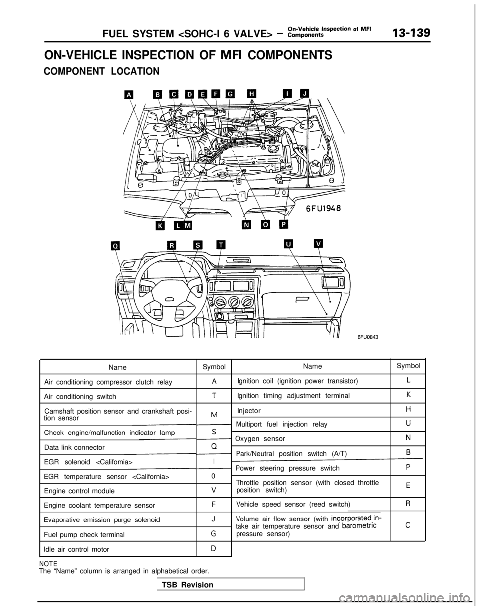
ON-VEHICLE INSPECTION OF MFI COMPONENTS
COMPONENT LOCATION
6FUO843
Name Symbol NameSymbol
Air conditioning compressor clutch relay A
Ignition coil (ignition power transistor)
L
Air conditioning switchTIgnition timing adjustment terminalK
Camshaft position sensor and crankshaft posi- InjectorHMtion sensor- Multiport fuel injection relayU
Check engine/malfunction indicator lampS- Oxygen sensorN
Data link connectorQ- Park/Neutral position switch (A/T)6
EGR solenoid I- Power steering pressure switchP
EGR temperature sensor 0
Throttle position sensor (with closed throttle
position switch)
EEngine control modulev
Engine coolant temperature sensorFVehicle speed sensor (reed switch)R
Evaporative emission purge solenoidJVolume air flow sensor (with incorporated,in-
take air temperature sensor and barometncC
Fuel pump check terminalGpressure sensor)
Idle air control motor
D
NOTEThe “Name” column is arranged in alphabetical order. TSB Revision
Page 289 of 1273
FUEL SYSTEM (SOHC-16 VALVE> - :::;::tt?ction Of MF’13-147
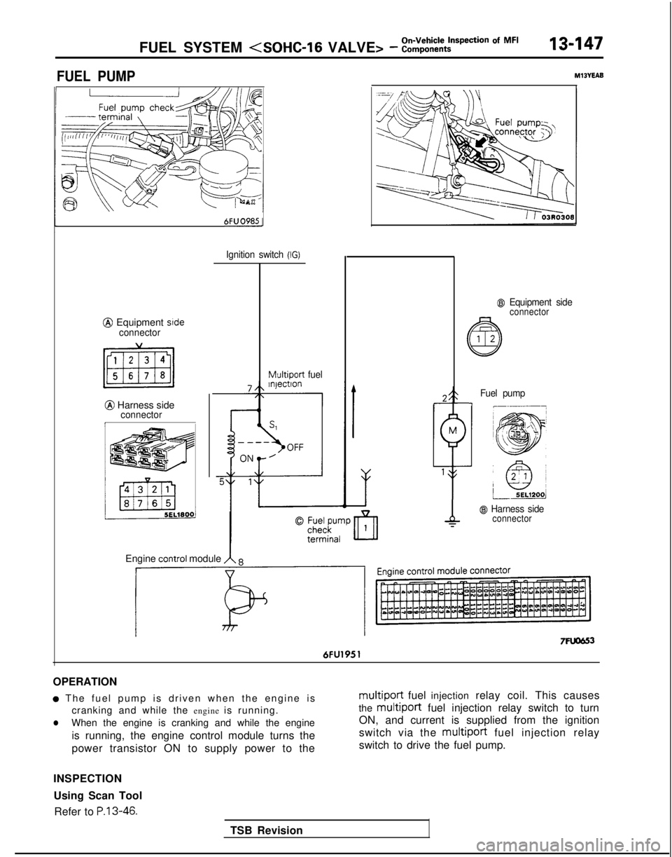
FUEL PUMPM13YEAB
6FUO985-
@ Equipment srdeconnector
@ Harness sideconnectorI
Ignition switch (IG)
Multiport
fuel
@I Equipment sideconnector
TSB Revision
Fuel pump-I
@ Harness sideconnector
Engine COntrOl module A 8
7Fuom 6FU1951
OPERATION
a The fuel pump is driven when the engine i
s
cranking and while the engine is running.
lWhen the engine is cranking and while the engine
is running, the engine control module turns the
power transistor ON to supply power to the
multiport fuel injection relay coil. This causes
the
multiport fuel injection relay switch to turn
ON, and current is supplied from the ignition
switch via the multiport
fuel injection relay
switch to drive the fuel pump.
INSPECTION Using Scan Tool Refer to
P.13-46.