Page 1030 of 1273
ACTIVE-ELECTRONIC CONTROL SUSPENSION - %ii%:justment 33B-91
Indicator lights that illuminate for 0.5
second after ECU power ON
Control mode AUTO mode indi-
cator
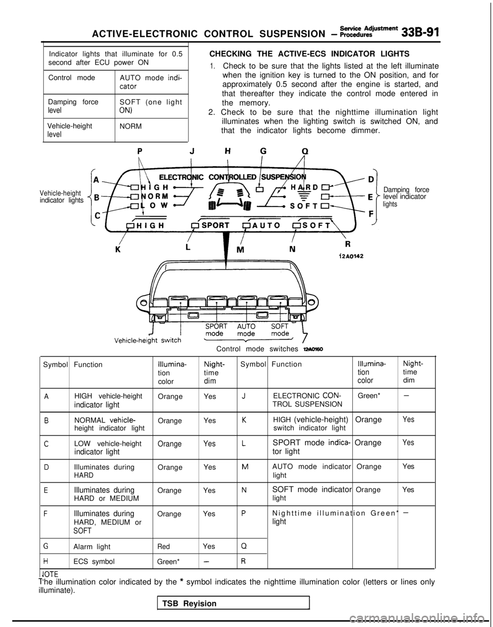
CHECKING THE ACTIVE-ECS INDICATOR LIGHTS
1.Check to be sure that the lights listed at the left illuminate
when the ignition key is turned to the ON position, and for
approximately 0.5 second after the engine is started, and
that thereafter they indicate the control mode entered in
Damping force
level
Vehicle-height
level
SOFT (one light
ON)
NORM the memory.
2. Check to be sure that the nighttime illumination light illuminates when the lighting switch is switched ON, and
that the indicator lights become dimmer.
Vehicle-heightindicator lights Damping forcelevel indicatorlights
12A0142
Control mode switches -60
Symbol FunctionIllumina-Night-
Symbol FunctionIllumina- Night-
tion time
tiontime
color
dim colordim
AHIGH vehicle-height
OrangeYesJELECTRONIC CON-Green* -
indicator lightTROL SUSPENSION
BNORMAL vehicle-OrangeYesKHIGH (vehicle-height) OrangeYes
height indicator light switch indicator light
CLOW vehicle-heightOrangeYesLSPORT mode indica- OrangeYes
indicator lighttor light
DIlluminates during
OrangeYesMAUTO mode indicator Orange Yes
HARDlight
EIlluminates duringOrange
YesNSOFT mode indicator Orange Yes
HARD or MEDIUM light
FIlluminates duringOrange
YesPNighttime illumination Green* -
HARD, MEDIUM orlight
SOFT
GAlarm lightRedYesQ
HECS symbol
Green* -R
IA-r-Cl”lCT‘he illumination color indicated by the * symbol indicates the nighttime illumination color (letters or lines on\
ly
illuminate).
TSB Reyision
Page 1031 of 1273
33B-92 ACTIVE-ELECTRONIC CONTROL SUSPENSION - ~~:%:?stment
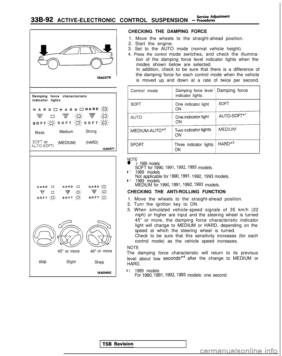
CHECKING THE DAMPING FORCE
12A0279
Damping force characteristic
indicator lights
,\,IHARD 0 HARD 0 HARD;g!;
=-\\I, =\\ l,=0 -=-,F; f;F:
SOFT ,gi SOFT
WeakMediumStrong
:SOFT or(MEDIUM)(HARD)4UTOSOFT)12AQ271
./I,HARD 0HARD 0HARD ;g;
z-0 -\k 3,\I I,SOFT ;p;SOFT ;R-SOFT I@;
45” or more45” or more
stopSlight
Sharp
16AQ460
1. Move the wheels to the straight-ahead position.
2. Start the engine.
3. Set to the AUTO mode (normal vehicle height).
4. Press the control mode switches, and check the illumina-
tion of the damping force level indicator lights when themodes shown below are selected.In addition, check to be sure that there is a difference of
the damping force for each control mode when the vehicle
is moved up and down at a rate of twice per second.
Control mode Damping force level
1 Damping force
indicator lights
SOFTOne indicator light
ON SOFT
SPORT
I
Three indicator lightsHARDe3
ON
NOTEl I- 1989 modelsSOFT for 1990,1991,1992,1993 models.l *:1989 modelsNot applicable for 1990,1991, 1992, 1993 models.l 3:1989 modelsMEDIUM for 1990,1991,1992,1993 models.
CHECKING THE ANTI-ROLLING FUNCTION
1. Move the wheels to the straight-ahead position.
2. Turn the ignition key to ON.
3. When simulated vehicle-speed signals of 35 km/h (22 mph) or higher are input and the steering wheel is turned
45” or more, the damping force characteristic indicator light will change to MEDIUM or HARD, depending on the
speed at which the steering wheel is turned. Check to be sure that this sensitivity increases (for each
control mode) as the vehicle speed increases.
NOTE
The damping force characteristic will return to its previous
level about tow seconds*4
after the change to MEDIUM or
HARD.
l 4:1989 modelsFor 1990,1991,1992,1993
models: one second
Page 1032 of 1273
Service AdjustmentACTIVE-ELECTRONIC CONTROL SUSPENSION - Procedures33B-93
\\ I/HARD ;g;
7 #
SOFT;#c
\\ I/HARD ;F;
7 ;&
SOFT;@;
I12AO399
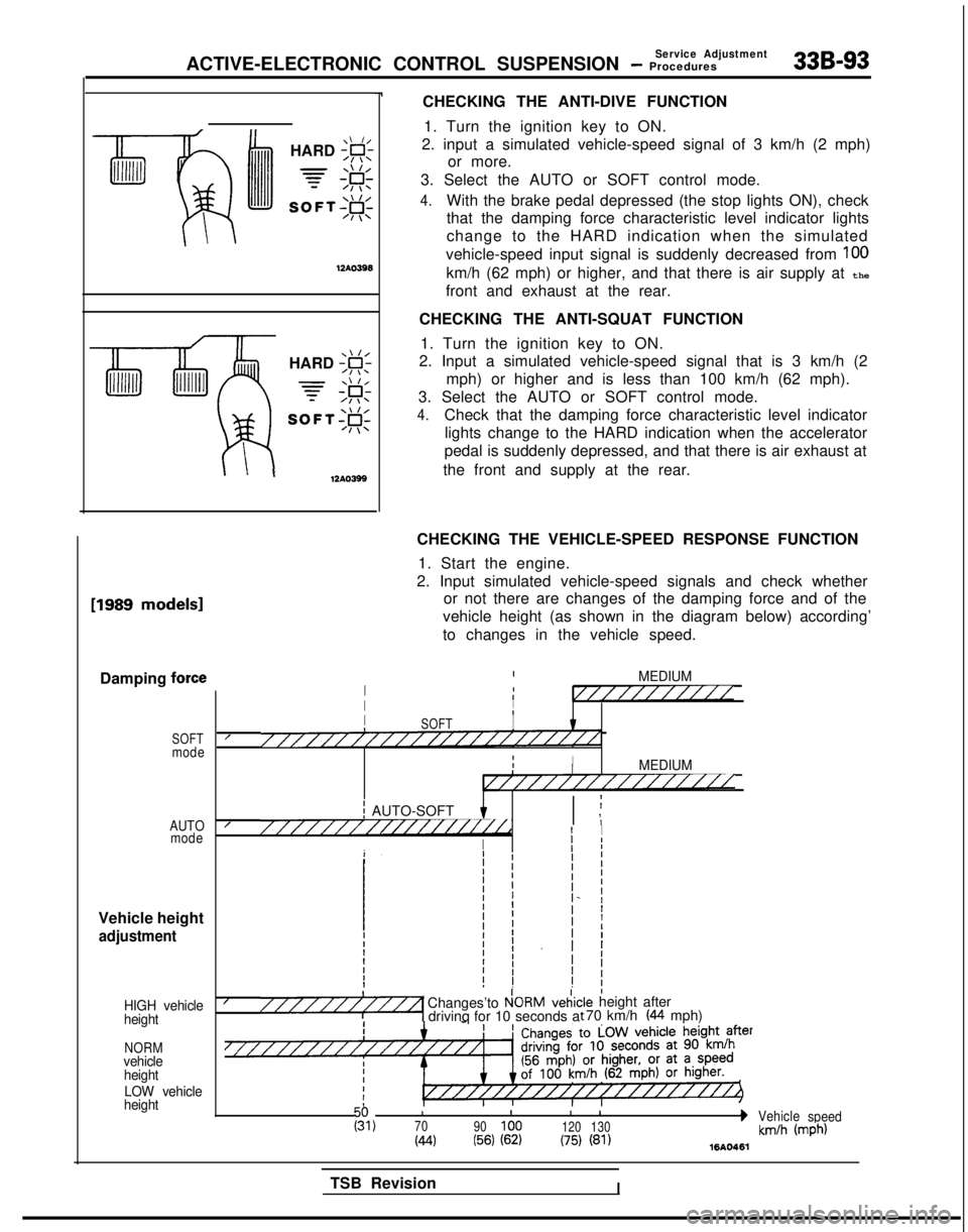
CHECKING THE ANTI-DIVE FUNCTION1. Turn the ignition key to ON.
2. input a simulated vehicle-speed signal of 3 km/h (2 mph) or more.
3. Select the AUTO or SOFT control mode.
4.With the brake pedal depressed (the stop lights ON), check
that the damping force characteristic level indicator lights
change to the HARD indication when the simulated
vehicle-speed input signal is suddenly decreased from
100
km/h (62 mph) or higher, and that there is air supply at the
front and exhaust at the rear.
CHECKING THE ANTI-SQUAT FUNCTION 1. Turn the ignition key to ON.
2. Input a simulated vehicle-speed signal that is 3 km/h (2
mph) or higher and is less than 100 km/h (62 mph).
3. Select the AUTO or SOFT control mode.
4.Check that the damping force characteristic level indicator lights change to the HARD indication when the accelerator
pedal is suddenly depressed, and that there is air exhaust at
the front and supply at the rear. [1989
models1
Damping force
SOFTmode
AUTO mode
Vehicle height
adjustment
HIGH vehicle
height
NORMvehicle
height
LOW vehicle
height
CHECKING THE VEHICLE-SPEED RESPONSE FUNCTION
1. Start the engine.
2. Input simulated vehicle-speed signals and check whether or not there are changes of the damping force and of the
vehicle height (as shown in the diagram below) according’
to changes in the vehicle speed.
IMEDIUMI1I//////////IIIII8SOFTI////////////////////////IIIIMEDIUMI////////////////
j AUTO-SOFT I ;I ,////////////////i//dI I
I
Ij I
I/Changes’to P!ORMveiic“““““1 drivinq for 10 seconds a:le height after t 70 km/h (44 mph)
III
I 1g,70
90100 120130bVehicle
speed
(44(56) (62)(75) (81)km/h (mph)1610461
TSB RevisionI
Page 1079 of 1273
338-140 ACTIVE-ELECTRONIC CONTROL SUSPENSION - t:%%%=mb’y’
INDICATOR ASSEMBLY
SERVICE POINTS OF REMOVAL(1) Using a plastic trim tool, remove the indicator assembly from the instrument panel.
(2) Disconnect the connector and remove the indicator assembly.
INSPECTION
(1) Indicator light does not light (the circuit, light bulb, or LED have failed).
NOTE
Operate the ECS and check to see that the light bulbs and
LED light.
(2) Do the lights loose intensity when the lighting switch is placed at
50 0:and$D . For procedures for other
inspections, refer to the troubleshooting section.
CONTROL UNIT
SERVICE POINTS OF REMOVAL
(1) Remove the trunk side trim. (Refer to GROUP
52-Trims.)
(2) Remove the installation bolts and connectors, and then
remove the control unit.
INSPECTION Referring to the troubleshooting section, check whether there
is terminal voltage.
TSB Revision
Page 1140 of 1273
SERVICE BRAKES - Anti-lock Braking System Troubleshooting35-19
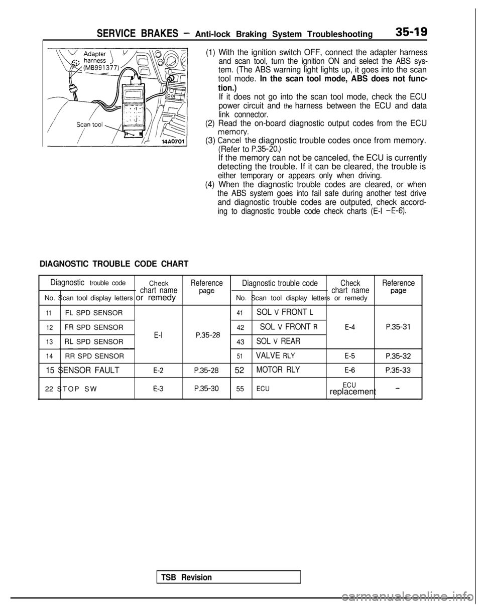
(1) With the ignition switch OFF, connect the adapter harness
and scan tool, turn the ignition ON and select the ABS sys-
tem. (The ABS warning light lights up, it goes into the scan
tool mode.
In the scan tool mode, ABS does not func-
tion.)
If it does not go into the scan tool mode, check the ECU
power circuit and
the harness between the ECU and data
link connector.
(2) Read the on-board diagnostic output codes from the ECU
(3) ?a\?zl’ythe diagnostic trouble codes once from memory.
(Refer to P.35-20.)
If the memory can not be canceled, the ECU is currently
detecting the trouble. If it can be cleared, the trouble is
either temporary or appears only when driving.
(4) When the diagnostic trouble codes are cleared, or when
the ABS system goes into fail safe during another test drive
and diagnostic trouble codes are outputed, check accord-
ing to diagnostic trouble code check charts (E-l -E-6).
DIAGNOSTIC TROUBLE CODE CHART
Diagnostic trouble code CheckReferenceDiagnostic trouble codeCheckReference
chart name
pawchart namepawNo. Scan tool display letters or remedy No. Scan tool display letters or remedy
11FL SPD SENSOR41SOL V FRONT L
12FR SPD SENSOR42SOL V FRONT RE-4P.35-31
E-lP.35-2813RL SPD SENSOR
43SOL V REAR
14RR SPD SENSOR51VALVE RLYE-5P.35-32
15 SENSOR FAULTE-2P.35-28 52MOTOR RLYE-6P.35-33
22 STOP SWE-3P.35-30 55ECU ECUreplacement -
TSB Revision
Page 1142 of 1273
SERVICE BRAKES - Anti-lock Braking System Troubleshooting35-21
A ABS warning light does not light at all.
[Explanation]
When it does not light up at all, there is a strong
possibility that there is trouble with ABS warning
light or with power to the light.
[Hint]
If other warning lights do not light up either, fuse is
probably blown.
MAIN FUSIBLE
LINK @IGNITIONSWITCH (IG2)IGNITIONSWITCH (IGl)
Ea
1
0 U
, ,8--1I
CL
, VALVE
fI*I1 RELAY 1 Ii 1,
M
i 10
z 13-
--3z2-&
rc11_ 3
t”71
_----
a-II
2
dt II
zz
c:
35 126J.27ABS ECU
1
GND GND GNDv v v
TSB RevisionI
14A0085
Page 1143 of 1273
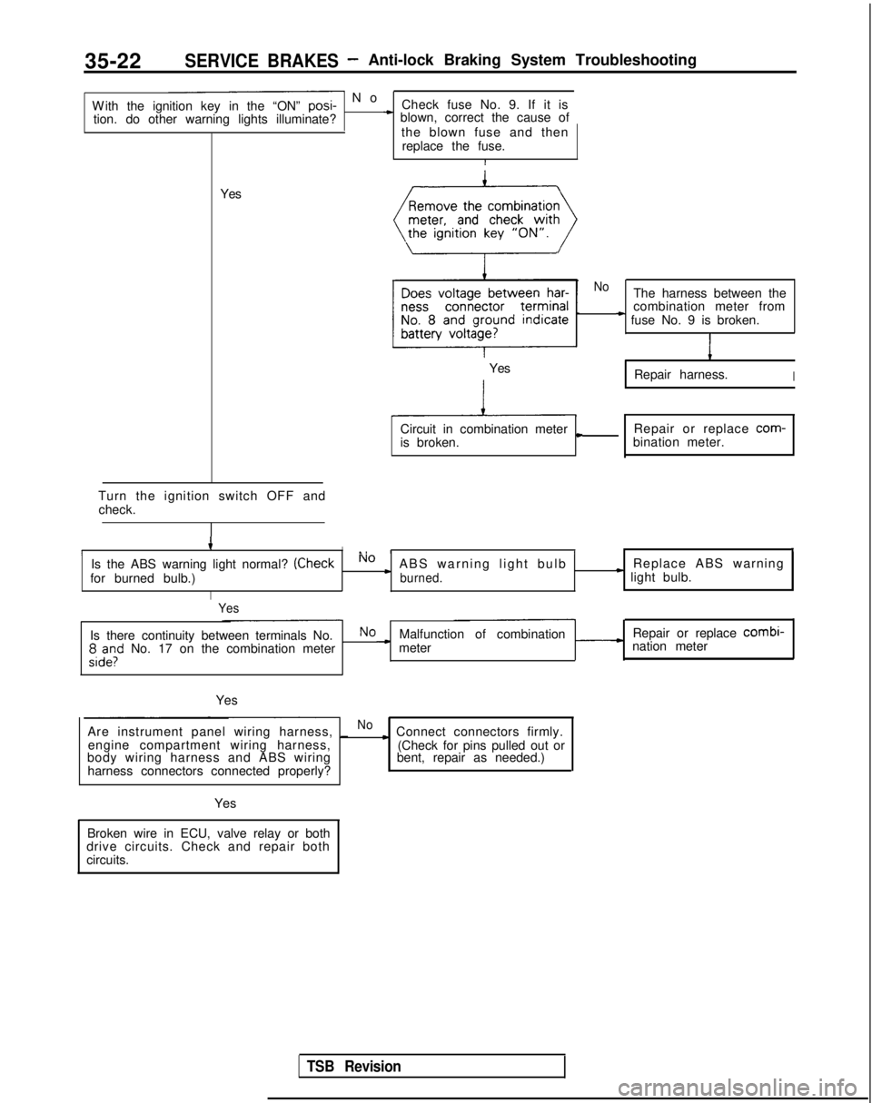
35-22SERVICE BRAKES- Anti-lock Braking System Troubleshooting
- N
o
With the ignition key in the “ON” posi-
Check fuse No. 9. If it is
tion. do other warning lights illuminate?
* blown, correct the cause of
the blown fuse and thenreplace the fuse.
I
Yes
Turn the ignition switch OFF and check.
4II., III,
Is the ABS warning light normal? (CheckNo cABS warning light bulb Replace ABS warning
for burned bulb.)burned.* light bulb.
I
Yes
NoThe harness between the
combination meter from
* fuse No. 9 is broken.
1
Repair harness.I
Circuit in combination metercRepair or replace com-
is broken. bination meter.
Yes
Is there continuity between terminals No.NoMalfunction of combination Repair or replace combi-
;,d”,l” No. 17 on the combination meter -meter
nation meter
Yes
Are instrument panel wiring harness, _
Noc Connect connectors firmly.
engine compartment wiring harness,
body wiring harness and ABS wiring
harness connectors connected properly? (Check for pins pulled out or
bent, repair as needed.)
Yes
Broken wire in ECU, valve relay or both
drive circuits. Check and repair both
circuits.
TSB Revision
Page 1151 of 1273
![MITSUBISHI GALANT 1989 Service Repair Manual 35-30SERVICE BRAKES - Anti-lock Braking System Troubleshooting
E-3When diagnostic trouble code “22 STOP SW” is displayed1
[Explanation][Hint]
The ABS ECU outputs this diagnostic trouble codeIf the MITSUBISHI GALANT 1989 Service Repair Manual 35-30SERVICE BRAKES - Anti-lock Braking System Troubleshooting
E-3When diagnostic trouble code “22 STOP SW” is displayed1
[Explanation][Hint]
The ABS ECU outputs this diagnostic trouble codeIf the](/manual-img/19/57312/w960_57312-1150.png)
35-30SERVICE BRAKES - Anti-lock Braking System Troubleshooting
E-3When diagnostic trouble code “22 STOP SW” is displayed1
[Explanation][Hint]
The ABS ECU outputs this diagnostic trouble codeIf the stop light operates normal, the ABS harness
in the following cases.wire for the stop light switch input circuit to the ECU
lStop light switch may remain on for more thanis broken or there is a malfunction in the ABS ECU.
15 minutes without the ABS functions.
lThe harness wire for the stop light switch may be open.
SUB FUSIBLELINK @
ABSECU
[1121314/5161716~9~10~11~12~13~14~15(16~17~18]~19DOC1122~3~4125l26~27~2~2913013ll3Z~33(341351
Do the stop lights light up
and go out normally?No c Check the stop light re-
lated circuit and repair
problem spots.
Yes
connector and inspectat
the harness side connec-
When the brake pedal is
_NoHarness wire between
pressed forcefully, does the
voltage between connector stop light switch and ABS
ECU is broken.
terminal No. 29 and ground
indicate battery voltage?
c
Repair harness.
Yes r
Malfunction of ABS ECU Replace ABS ECU.
I
14AO683
TSB Revision