Page 388 of 1273
13-246FUEL SYSTEM - Sewice Adjustment Procedures
17k&---,!E~,~~/iY I
(1) The vehicle should be prepared as follows before the
inspection and adjustment.
l Engine coolant temperature:
85-95°C (185-205°F)
l Lights, electric cooling fan and accessories: OFF l Transaxle: Neutral (P for vehicles with an automatic transaxle)
(2) Connect the scan tool to the data link connector (white).
NOTE
When the scan tool is connected, the diagnostic test mode
control terminal is grounded.
(3) If the scan tool is not used, follow the steps below.
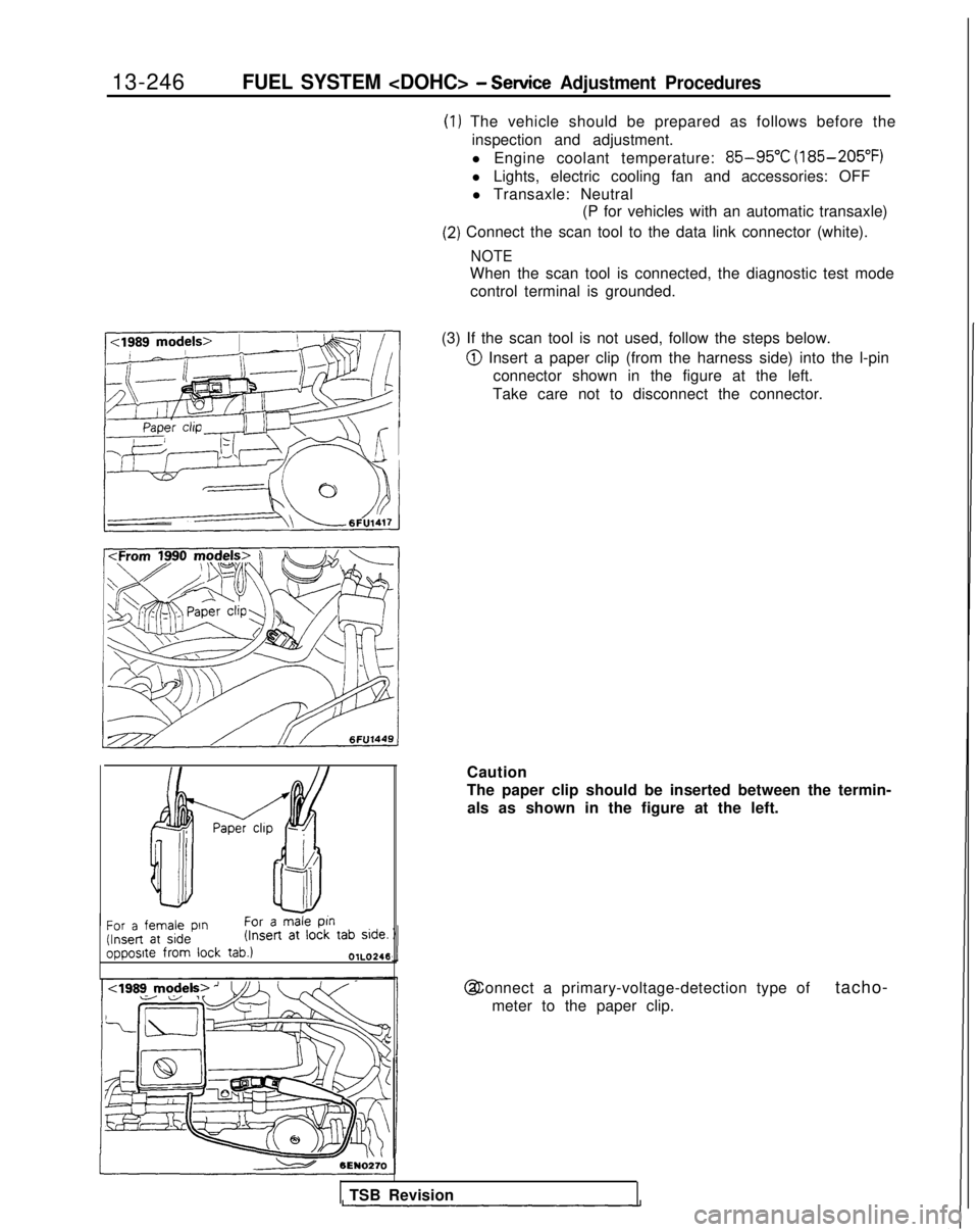
@ Insert a paper clip (from the harness side) into the l-pin connector shown in the figure at the left.
Take care not to disconnect the connector.
/ Paper chp -
f!f--i!t
Ah
-II
For a female pin
For a male
ptn (Insert
at side (Insert
at
lock tab side.
opposite from
lock
tab.)OlL0246
Caution
The paper clip should be inserted between the termin-
als as shown in the figure at the left. @ Connect a primary-voltage-detection type of
tacho-
meter to the paper clip.
TSB Revision
Page 404 of 1273
13-262FUEL SYSTEM - On-Vehicle Inspection of MFI Components
INSPECTION
Using Scan tool
1 Data 12reading
L
Data displayInspection conditions
Sensor de-. Engine coolanttection airtemperature: 85-95°Cvolume (fre-(185-205°F)quency) .Lights, cooling fan, elec-trical accessories: OFF. Transaxle: neutral (PJTmodels: “P” range)
Engine condition
Idling
2,000 rpm
Racing
Standard value 25-50
Hz 30-50 Hz
60-90 Hz 50-80 Hz
Frequency increases as
racing rpm increases.
NOTEThe volume air flow sensor output frequency may be about 10% higher than\
indicated above when the vehicle is new
[driven approximately 500 km(300 miles) or less].
i
Regular waveform03AO203
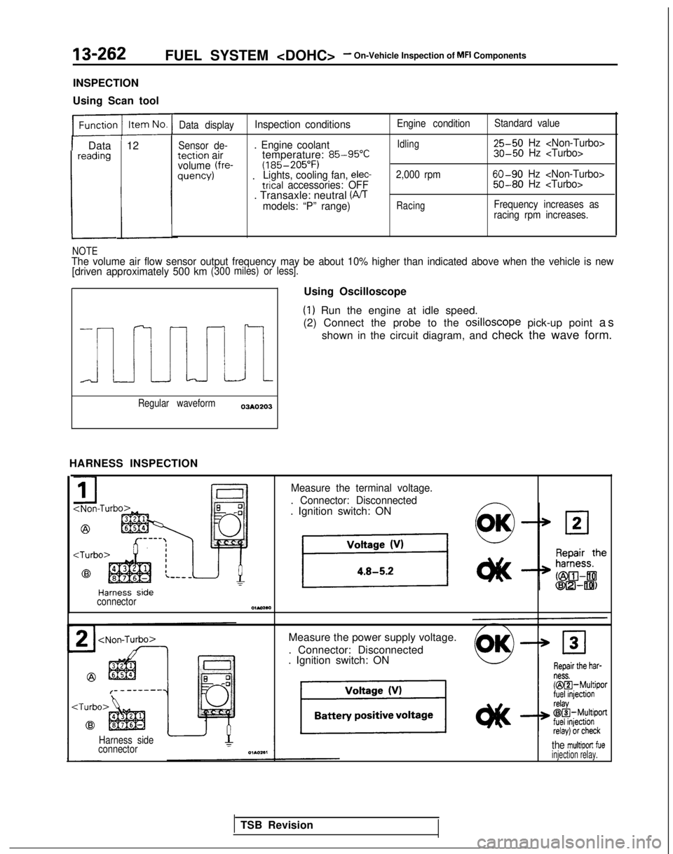
HARNESS INSPECTION Using Oscilloscope
(1) Run the engine at idle speed.
(2) Connect the probe to the osilloscope
pick-up point as
shown in the circuit diagram, and check the wave form.
Measure the terminal voltage.
. Connector: Disconnected
. Ignition switch: ON
connectorOlMaa
Measure the power supply voltage.
. Connector: Disconnected
. Ignition switch: ON
Harness side
connectorthe multiport fueinjection relay.
TSB Revision
Page 438 of 1273
13-296FUEL SYSTEM -On-Vehicle
Inspection
of
MFI
Components
INSPECTION
Using Scan tool
Function Item No. Data displayInspection conditionsEngine coolant temperature Standard value1
Data 41;ctJ$onEngine crankingAt 0°C (32”F)*2Approx. 17 ms
readingApprox. 40 ms
At 20°C (68°F)Approx. 38 ms
Approx. 19 ms
At 80°C (176°F)Approx. 9 ms
Approx. 4.5 ms
Function
Datareading
3TE Item No.
41
Data display
$ctX$on
Inspection conditionsEngine condition
Standard value
. Engine coolant tempera-Idling2.4-3.2 ms
ture:1.6-2.6 ms 85-95°C
(185-205°F)
. Lights, cooling fan, electric- 2,000 rpm1.9-2.9
ms
al accessories: OFF1.4-2.2 ms . Transaxle: neutralDuring sudden Increasesracing
+l:The injector activation time indicates the time under the following cond\
itions: a power source voltage of 11V and acranking rpm of 250 rpm or less.*2: Simultaneous injection at four cylinders when engine coolant temperatur\
e is 0°C (32°F).*3: The injector activation time may be about 10% longer than indicated abo\
ve when the vehicle is new [driven
approximately 500 km (300 miles) or less].
Function Item No.Description Inspection conditionsNormal indication
Actuator test 01No. 1 injector is shut off.
Engine: idling after warmThe idling condition
02No. 2 injector is shut off.?!hut off the injectors inchanges more.
(Either becomes more un-
03
No. 3 injector is shut off.
04
No.4 injector is shut off.
sequence during after
engine warm-up, check
the idling condition.) stable, or engine stalls.)
,d&- A: InjectorNormal wavetormdrive time
HARNESS INSPECTION
@ Harness sideconnector
I
L
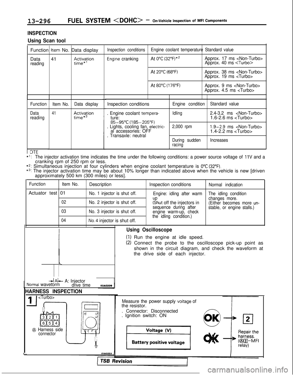
Using Oscilloscope
(1) Run the engine at idle speed.
(2) Connect the probe to the oscilloscope pick-up point as
shown in the circuit diagram, and check the waveform at
the drive side of each injector.
Measure the power supply voltage ofthe resistor.
. Connector: Disconnected. Ignition switch: ON
1 TSB hevision
Page 441 of 1273
FUEL SYSTEM -On-Vehicle Inspection of
MFI Components13-299
OPERATION
l The amount of air taken in during idling is
regulated by the opening and closing of the
servo valve located in the air passage that
bypasses the throttle valve.
l The servo valve is opened or closed by the
activation of the stepper motor (incorporated
within the idle air control motor) in the forward
or reverse direction.
TROUBLESHOOTING HINTS
Hint 1: If the number of stepper motor steps increases to
IOO- 120 steps or decreases
to 0 step, the cause may be presumed to be a malfunction of the stepper motor or
damaged or disconnected wiring of the
harness.
Hint 2: If the number of stepper motor steps
deviates from the standard value even
though the results of the checking of the
harness of the idle air control motor and of
the comoonent
itself indicate no abnormal
condition, the cause may be presumed to be one of the following.
INSPECTION
Using Scan tool
lBattery power supply is supplied, by way of the
multiport fuel injection relay, to the coil of the
stepper motor. The engine control module
switches ON the power transistors (located
within the engine control module) in sequential
order, and, when current flows to the stepper motor coil, the stepper motor is activated in the
forward or reverse direction.
(1) Improper adjustment of the standard
idling speed.
(2) Deposits adhered to the throttle valve.
(3) Leakage of air into the intake manifold
from a gasket gap, etc.
(4) Incomplete close contact of the EGRvalve seat.
(5) Incomplete combustion within the
cylinder.
(Malfunction of the spark plugs, the
ignition coil, the iniectors,
the
com- pression
pressure, etc.)
FunctionItem No.Data display Check conditions Load conditionsStandard value
Data reading 45Steppermotor steps. Engine coolant tempera-
. Air conditioning
4-14Step
ture:switch: OFF 85-95°C
(185-205°F)
. Lights, electrical cooling
:$b::pfan and accessories: OFF
. Transaxle: neutral
. Closed throttle switch: ON
- Air conditioning 20-60 Step
switch: ON
(The compressor clutchshould be activated when
the air conditioning switch;J-;;o~P
is switched ON.)* Engine: idling
1;:!,1;:!,
/!-I\/!-I\
f$&$:”f$&$:”
! ,‘,! ,‘,
4);4);
;jj\(Q(j!jGZ-);jj\(Q(j!jGZ-)
lili
q#Q~Hq#Q~HF]F]
ii 2 L J 2 L ~ -0SClllO 4ii 2 L J 2 L ~ -0SClllO 4
NOTE
When the vehicle is new (driven approximately 500 km (300 miles) or l\
ess) the number of steps may be about
30 steps greater than the standard value indicated above.
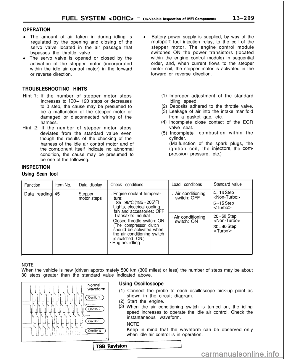
Using Oscilloscope
(1) Connect the probe to each oscilloscope pick-up point as
shown in the circuit diagram.
(2) Start the engine.
(3) When the air conditioning switch is turned on, the idling speed increases to operate the idle air control. Check theinstantaneous waveform.
NOTE
Keep in mind that the waveform can be observed only
when idle air control is in operation.
Page 516 of 1273
13-374AUTO-CRUISE CONTROL SYSTEM - Troubleshooting
CIRCUIT DIAGRAM (CONTINUED)
J/B
AUTO CRUISECONTROL ACTUATOR
DIODE
c-49
J/B
1
STOP LIGHTSWITCH
C-48
f 2
B94
AUTO-CRUISE
CONTROL UNITc-01
F
(7 52
z
d
,,l
\, .$'4 3
2
?
-
%
6
1,
?
s
60
OPEN
CONNEC
TOR
c-47
:
STOP LIGHT
J/B
E-7
ALI
m
--7C
2‘\I
[email protected]
5
n 1~2~3I4I516171E
I 8 I10~11~12112,14~15,16,1~
3 c-50
1
1: C$!&NAT'ON
16C-52
C-40
i
.
5
WC-18
EBT&k48W
TSB Revision
Page 540 of 1273
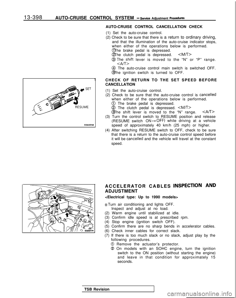
13-398
AUTO-CRUISE CONTROL SYSTEM - Setice Adjustment procedures
03*02.5*
1
AUTO-CRUISE CONTROL CANCELLATION CHECK
(1) Set the auto-cruise control.
(2) Check to be sure that there is a return to ordinary driving,
and that the illumination of the auto-cruise indicator stops,
when either of the operations below is performed. @ The brake pedal is depressed.
@ The clutch pedal is depressed.
@ TJhEzift lever is moved to the “N” or “P” range.
@I The auto-cruise control main switch is switched OFF.
@ The ignition switch is turned to OFF.
CHECK OF RETURN TO THE SET SPEED BEFORE
CANCELLATION (1) Set the auto-cruise control.
(2) Check to be sure that the auto-cruise control is
cancelled
when either of the operations below is performed.
@ The brake pedal is depressed.
@ The clutch pedal is depressed. @ The shift lever is moved to the “N” range.
CAST>
(3) Turn the control switch to RESUME position and release
(RESUME switch
ON*OFF) while driving at a vehicle
speed of approximately 40 km/h (25 mph) or higher.
(4) After switching RESUME switch to OFF, check to be sure that there is a return to the auto-cruise control speed before
it will be
cancelled and the vehicle will travel at the constant
speed.
ACCELERATOR CABLES INSPECTION AND
ADJUSTMENT
(I) Turn air conditioning and lights OFF. Inspect and adjust at no load.
(2) Warm engine until stabilized at idle.
(3) Confirm idle speed is at prescribed rpm.
(4) Stop engine (ignition switch OFF).
(5) Confirm there are no sharp bends in accelerator cables.
(6) Check inner cables for correct slack.
(7) If there is too much slack or no slack, adjust play by the following procedures.
0 Remove the actuator’s protector.
0 On models with an SOHC engine, turn the ignition
switch to the ON position (without starting the engine)
and leave in that condition for approximately 15
seconds.
TSB Revision
Page 973 of 1273
33B-34 ACTIVE-ELECTRONIC CONTROL SUSPENSION - Troubleshooting
[7] ACTIVE-ECS indicators circuit
Battery
Column switch
-------
c n-21
f
ACTIVE-ECS 1indicator
I
(From 1990 models)
ECUII
F-17
Power source,circuif
/
EEzQ15~JgJ 1 ,2-LR
i181lllumlnatlon lightSPOK
1 1c
1’
I’
II
I 1
II
I IiI’
I I
/I
I’I 1
NOTEI-
* mark is applicable for 1991, 1992, 1993 models.ECUI TSB Revision
Page 989 of 1273
33B-50 ACTIVE-ELECTRONIC CONTROL SUSPENSION - Troubleshooting
1141 STOP LIGHT SWITCH CIRCUIT
Battew
I
P
I
C-36I
7 1 4*15A / JbJ;;ion
c-47
To stoplights F-l 6
1-1
183It
Target vehicle height order of priorityJ I
12A0495
TSB Revision