1989 FORD FIESTA engine
[x] Cancel search: enginePage 35 of 296
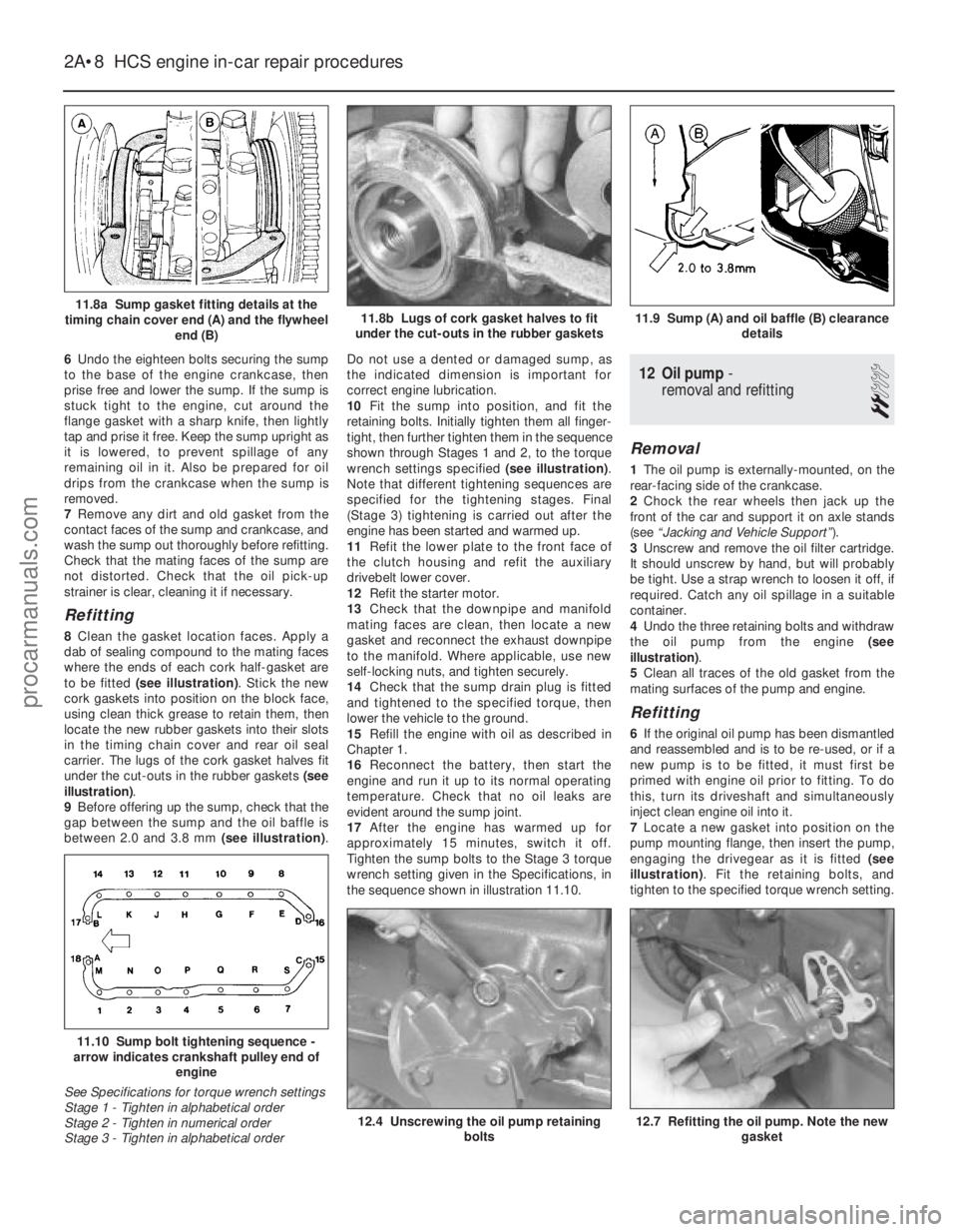
6Undo the eighteen bolts securing the sump
to the base of the engine crankcase, then
prise free and lower the sump. If the sump is
stuck tight to the engine, cut around the
flange gasket with a sharp knife, then lightly
tap and prise it free. Keep the sump upright as
it is lowered, to prevent spillage of any
remaining oil in it. Also be prepared for oil
drips from the crankcase when the sump is
removed.
7 Remove any dirt and old gasket from the
contact faces of the sump and crankcase, and
wash the sump out thoroughly before refitting.
Check that the mating faces of the sump are
not distorted. Check that the oil pick-up
strainer is clear, cleaning it if necessary.
Refitting
8 Clean the gasket location faces. Apply a
dab of sealing compound to the mating faces
where the ends of each cork half-gasket are
to be fitted (see illustration) . Stick the new
cork gaskets into position on the block face,
using clean thick grease to retain them, then
locate the new rubber gaskets into their slots
in the timing chain cover and rear oil seal
carrier. The lugs of the cork gasket halves fit
under the cut-outs in the rubber gaskets (see
illustration) .
9 Before offering up the sump, check that the
gap between the sump and the oil baffle is
between 2.0 and 3.8 mm (see illustration).Do not use a dented or damaged sump, as
the indicated dimension is important for
correct engine lubrication.
10
Fit the sump into position, and fit the
retaining bolts. Initially tighten them all finger-
tight, then further tighten them in the sequence
shown through Stages 1 and 2, to the torque
wrench settings specified (see illustration).
Note that different tightening sequences are
specified for the tightening stages. Final
(Stage 3) tightening is carried out after the
engine has been started and warmed up.
11 Refit the lower plate to the front face of
the clutch housing and refit the auxiliary
drivebelt lower cover.
12 Refit the starter motor.
13 Check that the downpipe and manifold
mating faces are clean, then locate a new
gasket and reconnect the exhaust downpipe
to the manifold. Where applicable, use new
self-locking nuts, and tighten securely.
14 Check that the sump drain plug is fitted
and tightened to the specified torque, then
lower the vehicle to the ground.
15 Refill the engine with oil as described in
Chapter 1.
16 Reconnect the battery, then start the
engine and run it up to its normal operating
temperature. Check that no oil leaks are
evident around the sump joint.
17 After the engine has warmed up for
approximately 15 minutes, switch it off.
Tighten the sump bolts to the Stage 3 torque
wrench setting given in the Specifications, in
the sequence shown in illustration 11.10.
12 Oil pump -
removal and refitting
2
Removal
1 The oil pump is externally-mounted, on the
rear-facing side of the crankcase.
2 Chock the rear wheels then jack up the
front of the car and support it on axle stands
(see “Jacking and Vehicle Support” ).
3 Unscrew and remove the oil filter cartridge.
It should unscrew by hand, but will probably
be tight. Use a strap wrench to loosen it off, if
required. Catch any oil spillage in a suitable
container.
4 Undo the three retaining bolts and withdraw
the oil pump from the engine (see
illustration) .
5 Clean all traces of the old gasket from the
mating surfaces of the pump and engine.
Refitting
6 If the original oil pump has been dismantled
and reassembled and is to be re-used, or if a
new pump is to be fitted, it must first be
primed with engine oil prior to fitting. To do
this, turn its driveshaft and simultaneously
inject clean engine oil into it.
7 Locate a new gasket into position on the
pump mounting flange, then insert the pump,
engaging the drivegear as it is fitted (see
illustration) . Fit the retaining bolts, and
tighten to the specified torque wrench setting.
2A•8 HCS engine in-car repair procedures
12.7 Refitting the oil pump. Note the new gasket12.4 Unscrewing the oil pump retaining bolts
11.10 Sump bolt tightening sequence -
arrow indicates crankshaft pulley end of
engine
See Specifications for torque wrench settings
Stage 1 - Tighten in alphabetical order
Stage 2 - Tighten in numerical order
Stage 3 - Tighten in alphabetical order
11.9 Sump (A) and oil baffle (B) clearance details11.8b Lugs of cork gasket halves to fit
under the cut-outs in the rubber gaskets11.8a Sump gasket fitting details at the
timing chain cover end (A) and the flywheel end (B)
1595Ford Fiesta Remakeprocarmanuals.com
http://vnx.su
Page 36 of 296
8Fit a new oil filter into position on
the oil pump body, as described in Chap-
ter 1.
9 Lower the vehicle to the ground, and top-
up the engine oil as described in “Weekly
Checks”.
13 Oil pump - dismantling,
inspection and reassembly
3
Dismantling
1 To inspect the oil pump components for
excessive wear, undo the retaining bolts and
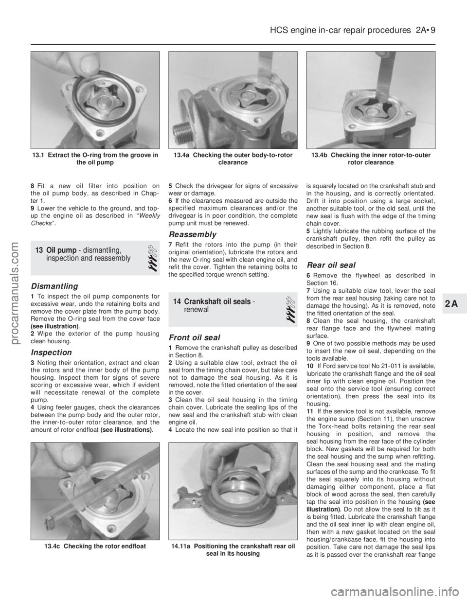
remove the cover plate from the pump body.
Remove the O-ring seal from the cover face
(see illustration) .
2 Wipe the exterior of the pump housing
clean housing.
Inspection
3 Noting their orientation, extract and clean
the rotors and the inner body of the pump
housing. Inspect them for signs of severe
scoring or excessive wear, which if evident
will necessitate renewal of the complete
pump.
4 Using feeler gauges, check the clearances
between the pump body and the outer rotor,
the inner-to-outer rotor clearance, and the
amount of rotor endfloat (see illustrations).5
Check the drivegear for signs of excessive
wear or damage.
6 If the clearances measured are outside the
specified maximum clearances and/or the
drivegear is in poor condition, the complete
pump unit must be renewed.
Reassembly
7 Refit the rotors into the pump (in their
original orientation), lubricate the rotors and
the new O-ring seal with clean engine oil, and
refit the cover. Tighten the retaining bolts to
the specified torque wrench setting.
14 Crankshaft oil seals -
renewal
3
Front oil seal
1 Remove the crankshaft pulley as described
in Section 8.
2 Using a suitable claw tool, extract the oil
seal from the timing chain cover, but take care
not to damage the seal housing. As it is
removed, note the fitted orientation of the seal
in the cover.
3 Clean the oil seal housing in the timing
chain cover. Lubricate the sealing lips of the
new seal and the crankshaft stub with clean
engine oil.
4 Locate the new seal into position so that it is squarely located on the crankshaft stub and
in the housing, and is correctly orientated.
Drift it into position using a large socket,
another suitable tool, or the old seal, until the
new seal is flush with the edge of the timing
chain cover.
5
Lightly lubricate the rubbing surface of the
crankshaft pulley, then refit the pulley as
described in Section 8.
Rear oil seal
6 Remove the flywheel as described in
Section 16.
7 Using a suitable claw tool, lever the seal
from the rear seal housing (taking care not to
damage the housing). As it is removed, note
the fitted orientation of the seal.
8 Clean the seal housing, the crankshaft
rear flange face and the flywheel mating
surface.
9 One of two possible methods may be used
to insert the new oil seal, depending on the
tools available.
10 If Ford service tool No 21-011 is available,
lubricate the crankshaft flange and the oil seal
inner lip with clean engine oil. Position the
seal onto the service tool (ensuring correct
orientation), then press the seal into its
housing.
11 If the service tool is not available, remove
the engine sump (Section 11), then unscrew
the Torx-head bolts retaining the rear seal
housing in position, and remove the
seal housing from the rear face of the cylinder
block. New gaskets will be required for both
the seal housing and the sump when refitting.
Clean the seal housing seat and the mating
surfaces of the sump and the crankcase. To fit
the seal squarely into its housing without
damaging either component, place a flat
block of wood across the seal, then carefully
tap the seal into position in the housing (see
illustration) . Do not allow the seal to tilt as it
is being fitted. Lubricate the crankshaft flange
and the oil seal inner lip with clean engine oil,
then with a new gasket located on the seal
housing/crankcase face, fit the housing into
position. Take care not damage the seal lips
as it is passed over the crankshaft rear flange
HCS engine in-car repair procedures 2A•9
13.4b Checking the inner rotor-to-outer rotor clearance13.4a Checking the outer body-to-rotor clearance13.1 Extract the O-ring from the groove inthe oil pump
14.11a Positioning the crankshaft rear oilseal in its housing13.4c Checking the rotor endfloat
2A
1595Ford Fiesta Remakeprocarmanuals.com
http://vnx.su
Page 37 of 296
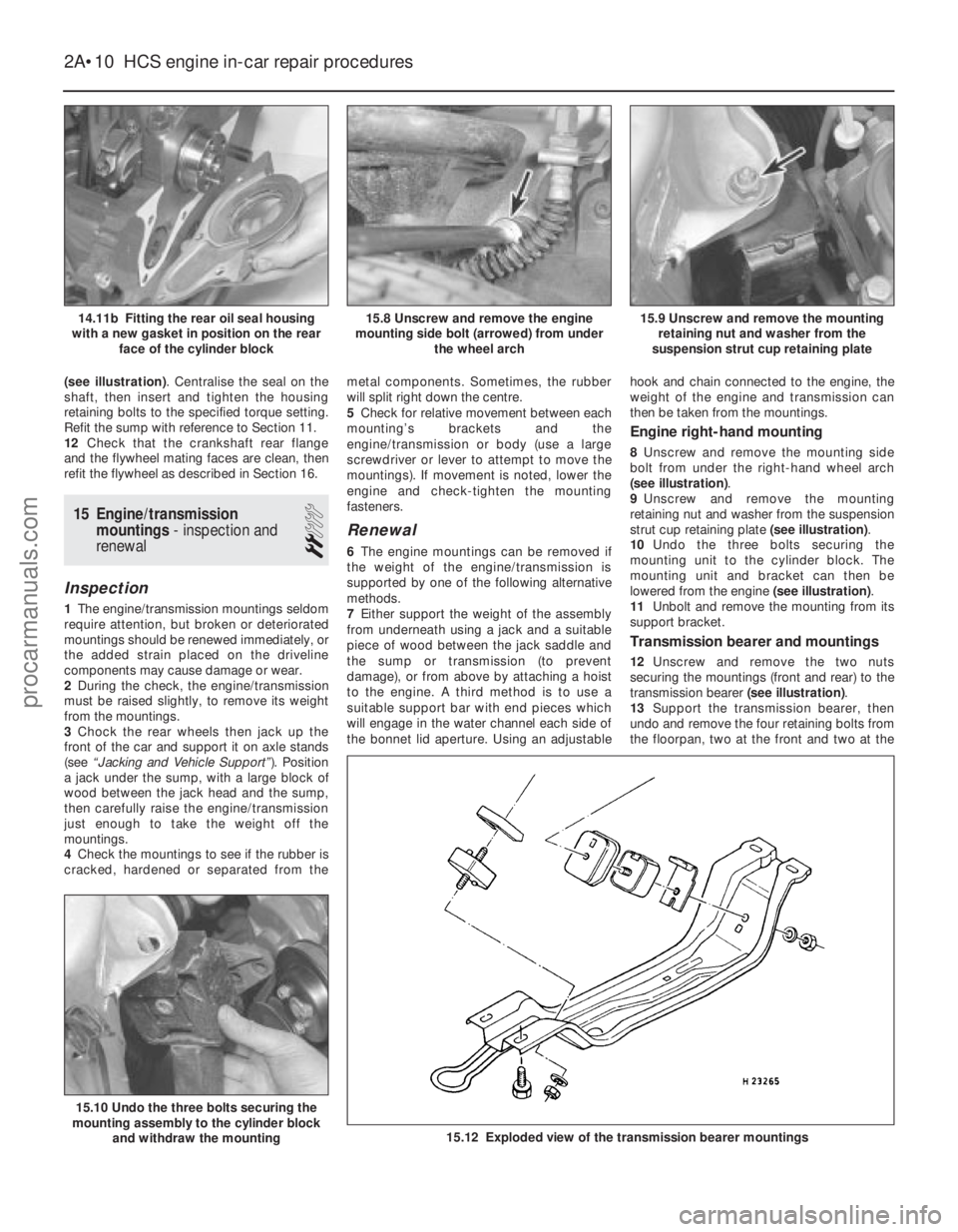
(see illustration). Centralise the seal on the
shaft, then insert and tighten the housing
retaining bolts to the specified torque setting.
Refit the sump with reference to Section 11.
12 Check that the crankshaft rear flange
and the flywheel mating faces are clean, then
refit the flywheel as described in Section 16.
15 Engine/transmission mountings - inspection and
renewal
2
Inspection
1 The engine/transmission mountings seldom
require attention, but broken or deteriorated
mountings should be renewed immediately, or
the added strain placed on the driveline
components may cause damage or wear.
2 During the check, the engine/transmission
must be raised slightly, to remove its weight
from the mountings.
3 Chock the rear wheels then jack up the
front of the car and support it on axle stands
(see “Jacking and Vehicle Support” ). Position
a jack under the sump, with a large block of
wood between the jack head and the sump,
then carefully raise the engine/transmission
just enough to take the weight off the
mountings.
4 Check the mountings to see if the rubber is
cracked, hardened or separated from the metal components. Sometimes, the rubber
will split right down the centre.
5
Check for relative movement between each
mounting’s brackets and the
engine/transmission or body (use a large
screwdriver or lever to attempt to move the
mountings). If movement is noted, lower the
engine and check-tighten the mounting
fasteners.
Renewal
6 The engine mountings can be removed if
the weight of the engine/transmission is
supported by one of the following alternative
methods.
7 Either support the weight of the assembly
from underneath using a jack and a suitable
piece of wood between the jack saddle and
the sump or transmission (to prevent
damage), or from above by attaching a hoist
to the engine. A third method is to use a
suitable support bar with end pieces which
will engage in the water channel each side of
the bonnet lid aperture. Using an adjustable hook and chain connected to the engine, the
weight of the engine and transmission can
then be taken from the mountings.
Engine right-hand mounting
8
Unscrew and remove the mounting side
bolt from under the right-hand wheel arch
(see illustration) .
9 Unscrew and remove the mounting
retaining nut and washer from the suspension
strut cup retaining plate (see illustration).
10 Undo the three bolts securing the
mounting unit to the cylinder block. The
mounting unit and bracket can then be
lowered from the engine (see illustration).
11 Unbolt and remove the mounting from its
support bracket.
Transmission bearer and mountings
12 Unscrew and remove the two nuts
securing the mountings (front and rear) to the
transmission bearer (see illustration).
13 Support the transmission bearer, then
undo and remove the four retaining bolts from
the floorpan, two at the front and two at the
2A•10 HCS engine in-car repair procedures
15.12 Exploded view of the transmission bearer mountings
15.10 Undo the three bolts securing the
mounting assembly to the cylinder block
and withdraw the mounting
15.9 Unscrew and remove the mountingretaining nut and washer from the
suspension strut cup retaining plate15.8 Unscrew and remove the engine
mounting side bolt (arrowed) from under the wheel arch14.11b Fitting the rear oil seal housing
with a new gasket in position on the rear face of the cylinder block
1595Ford Fiesta Remakeprocarmanuals.com
http://vnx.su
Page 38 of 296
rear, and lower the transmission bearer from
the vehicle. Note plate fitment, as applicable,
for reassembly.
14Unscrew the single nut securing each
mounting and its retainer to the transmission
support bracket, and remove. The
transmission support brackets are fixed
externally to the transmission casing and do
not need to be removed for this operation.
All mountings
15 Refitting of all mountings is a reversal of
removal. Make sure that the original sequence
of assembly of washers and plates is
maintained.
16 Do not fully tighten any mounting bolts
until they are all located. As the mounting
bolts and nuts are tightened, check that the
mounting rubbers do not twist.
16 Flywheel - removal, inspection
and refitting
3
Refitting
1 Remove the transmission as described in
Chapter 7A, then remove the clutch as
described in Chapter 6. 2
Unscrew the six retaining bolts, and remove
the flywheel from the rear end flange of the
crankshaft - take care not to drop the
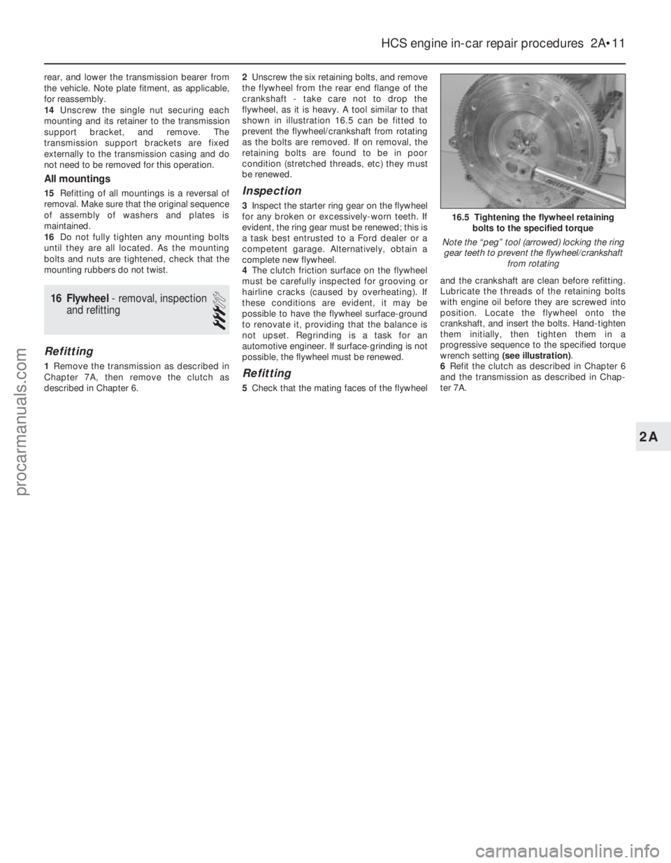
flywheel, as it is heavy. A tool similar to that
shown in illustration 16.5 can be fitted to
prevent the flywheel/crankshaft from rotating
as the bolts are removed. If on removal, the
retaining bolts are found to be in poor
condition (stretched threads, etc) they must
be renewed.
Inspection
3 Inspect the starter ring gear on the flywheel
for any broken or excessively-worn teeth. If
evident, the ring gear must be renewed; this is
a task best entrusted to a Ford dealer or a
competent garage. Alternatively, obtain a
complete new flywheel.
4 The clutch friction surface on the flywheel
must be carefully inspected for grooving or
hairline cracks (caused by overheating). If
these conditions are evident, it may be
possible to have the flywheel surface-ground
to renovate it, providing that the balance is
not upset. Regrinding is a task for an
automotive engineer. If surface-grinding is not
possible, the flywheel must be renewed.
Refitting
5 Check that the mating faces of the flywheel and the crankshaft are clean before refitting.
Lubricate the threads of the retaining bolts
with engine oil before they are screwed into
position. Locate the flywheel onto the
crankshaft, and insert the bolts. Hand-tighten
them initially, then tighten them in a
progressive sequence to the specified torque
wrench setting
(see illustration) .
6 Refit the clutch as described in Chapter 6
and the transmission as described in Chap-
ter 7A.
HCS engine in-car repair procedures 2A•11
16.5 Tightening the flywheel retaining bolts to the specified torque
Note the “peg” tool (arrowed) locking the ring gear teeth to prevent the flywheel/crankshaft from rotating
2A
1595Ford Fiesta Remakeprocarmanuals.com
http://vnx.su
Page 39 of 296
2A•12 HCS engine in-car repair procedures
1595Ford Fiesta Remake
Notes
procarmanuals.com
http://vnx.su
Page 40 of 296
2B
1595Ford Fiesta Remake
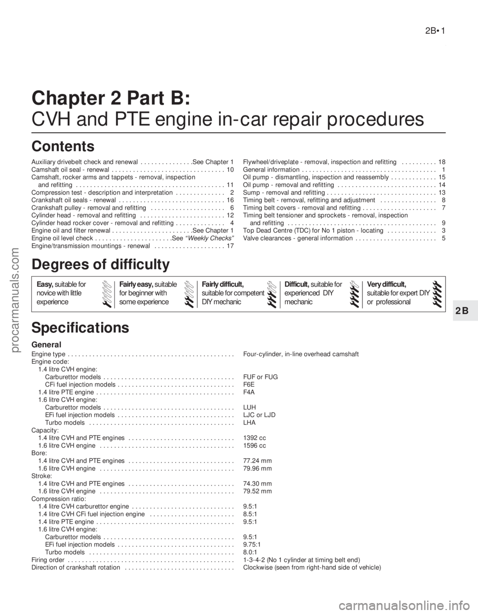
General
Engine type . . . . . . . . . . . . . . . . . . . . . . . . . . . . . . . . . . . .\
. . . . . . . . . . . Four-cylinder, in-line overhead camshaft
Engine code:1.4 litre CVH engine: Carburettor models . . . . . . . . . . . . . . . . . . . . . . . . . . . . . . . . . . . .\
. FUF or FUG
CFi fuel injection models . . . . . . . . . . . . . . . . . . . . . . . . . . . . . . . . . F6E
1.4 litre PTE engine . . . . . . . . . . . . . . . . . . . . . . . . . . . . . . . . . . . .\
. . . F4A
1.6 litre CVH engine: Carburettor models . . . . . . . . . . . . . . . . . . . . . . . . . . . . . . . . . . . .\
. LUH
EFi fuel injection models . . . . . . . . . . . . . . . . . . . . . . . . . . . . . . . . . LJC or LJD
Turbo models . . . . . . . . . . . . . . . . . . . . . . . . . . . . . . . . . . . .\
. . . . . LHA
Capacity:
1.4 litre CVH and PTE engines . . . . . . . . . . . . . . . . . . . . . . . . . . . . . . 1392 cc
1.6 litre CVH engine . . . . . . . . . . . . . . . . . . . . . . . . . . . . . . . . . . . .\
. . 1596 cc
Bore:
1.4 litre CVH and PTE engines . . . . . . . . . . . . . . . . . . . . . . . . . . . . . . 77.24 mm
1.6 litre CVH engine . . . . . . . . . . . . . . . . . . . . . . . . . . . . . . . . . . . .\
. . 79.96 mm
Stroke:
1.4 litre CVH and PTE engines . . . . . . . . . . . . . . . . . . . . . . . . . . . . . . 74.30 mm
1.6 litre CVH engine . . . . . . . . . . . . . . . . . . . . . . . . . . . . . . . . . . . .\
. . 79.52 mm
Compression ratio:
1.4 litre CVH carburettor engine . . . . . . . . . . . . . . . . . . . . . . . . . . . . . 9.5:1
1.4 litre CVH CFi fuel injection engine . . . . . . . . . . . . . . . . . . . . . . . . 8.5:1
1.4 litre PTE engine . . . . . . . . . . . . . . . . . . . . . . . . . . . . . . . . . . . .\
. . . 9.5:1
1.6 litre CVH engine: Carburettor models . . . . . . . . . . . . . . . . . . . . . . . . . . . . . . . . . . . .\
. 9.5:1
EFi fuel injection models . . . . . . . . . . . . . . . . . . . . . . . . . . . . . . . . . 9.75:1
Turbo models . . . . . . . . . . . . . . . . . . . . . . . . . . . . . . . . . . . .\
. . . . . 8.0:1
Firing order . . . . . . . . . . . . . . . . . . . . . . . . . . . . . . . . . . . .\
. . . . . . . . . . . 1-3-4-2 (No 1 cylinder at timing belt end)
Direction of crankshaft rotation . . . . . . . . . . . . . . . . . . . . . . . . . . . . . . . Clockwise (seen from right-hand side of vehicle)
Chapter 2 Part B:
CVH and PTE engine in-car repair procedures
Auxiliary drivebelt check and renewal . . . . . . . . . . . . . . .See Chapter 1
Camshaft oil seal - renewal . . . . . . . . . . . . . . . . . . . . . . . . . . . . . . . . 10
Camshaft, rocker arms and tappets - removal, inspection and refitting . . . . . . . . . . . . . . . . . . . . . . . . . . . . . . . . . . . .\
. . . . . . 11
Compression test - description and interpretation . . . . . . . . . . . . . . 2
Crankshaft oil seals - renewal . . . . . . . . . . . . . . . . . . . . . . . . . . . . . . 16
Crankshaft pulley - removal and refitting . . . . . . . . . . . . . . . . . . . . . 6
Cylinder head - removal and refitting . . . . . . . . . . . . . . . . . . . . . . . . 12
Cylinder head rocker cover - removal and refitting . . . . . . . . . . . . . . 4
Engine oil and filter renewal . . . . . . . . . . . . . . . . . . . . . . .See Chapter 1
Engine oil level check . . . . . . . . . . . . . . . . . . . . . .See
“Weekly Checks”
Engine/transmission mountings - renewal . . . . . . . . . . . . . . . . . . . . 17 Flywheel/driveplate - removal, inspection and refitting . . . . . . . . . . 18
General information . . . . . . . . . . . . . . . . . . . . . . . . . . . . . . . . . . . .\
. . 1
Oil pump - dismantling, inspection and reassembly . . . . . . . . . . . . . 15
Oil pump - removal and refitting . . . . . . . . . . . . . . . . . . . . . . . . . . . . 14
Sump - removal and refitting . . . . . . . . . . . . . . . . . . . . . . . . . . . . . . . 13
Timing belt - removal, refitting and adjustment . . . . . . . . . . . . . . . . 8
Timing belt covers - removal and refitting . . . . . . . . . . . . . . . . . . . . . 7
Timing belt tensioner and sprockets - removal, inspection
and refitting . . . . . . . . . . . . . . . . . . . . . . . . . . . . . . . . . . . .\
. . . . . . 9
Top Dead Centre (TDC) for No 1 piston - locating . . . . . . . . . . . . . . 3
Valve clearances - general information . . . . . . . . . . . . . . . . . . . . . . . 5
2B•1
Specifications Contents
Easy, suitable for
novice with little
experience Fairly easy,
suitable
for beginner with
some experience Fairly difficult,
suitable for competent
DIY mechanic
Difficult,
suitable for
experienced DIY
mechanic Very difficult,
suitable for expert DIY
or professional
Degrees of difficulty
54321
procarmanuals.com
http://vnx.su
Page 41 of 296
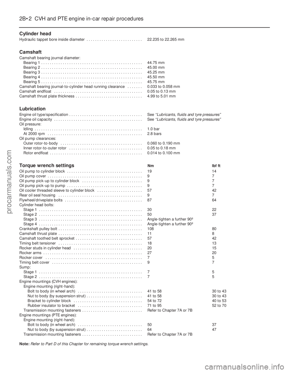
Cylinder head
Hydraulic tappet bore inside diameter . . . . . . . . . . . . . . . . . . . . . . . . . . 22.235 to 22.265 mm
Camshaft
Camshaft bearing journal diameter:Bearing 1 . . . . . . . . . . . . . . . . . . . . . . . . . . . . . . . . . . . .\
. . . . . . . . . . . 44.75 mm
Bearing 2 . . . . . . . . . . . . . . . . . . . . . . . . . . . . . . . . . . . .\
. . . . . . . . . . . 45.00 mm
Bearing 3 . . . . . . . . . . . . . . . . . . . . . . . . . . . . . . . . . . . .\
. . . . . . . . . . . 45.25 mm
Bearing 4 . . . . . . . . . . . . . . . . . . . . . . . . . . . . . . . . . . . .\
. . . . . . . . . . . 45.50 mm
Bearing 5 . . . . . . . . . . . . . . . . . . . . . . . . . . . . . . . . . . . .\
. . . . . . . . . . . 45.75 mm
Camshaft bearing journal-to-cylinder head running clearance . . . . . . . 0.033 to 0.058 mm
Camshaft endfloat . . . . . . . . . . . . . . . . . . . . . . . . . . . . . . . . . . . .\
. . . . . 0.05 to 0.13 mm
Camshaft thrust plate thickness . . . . . . . . . . . . . . . . . . . . . . . . . . . . . . . 4.99 to 5.01 mm
Lubrication
Engine oil type/specification . . . . . . . . . . . . . . . . . . . . . . . . . . . . . . . . . . See “Lubricants, fluids and tyre pressures”
Engine oil capacity . . . . . . . . . . . . . . . . . . . . . . . . . . . . . . . . . . . .\
. . . . . See “Lubricants, fluids and tyre pressures”
Oil pressure:
Idling . . . . . . . . . . . . . . . . . . . . . . . . . . . . . . . . . . . .\
. . . . . . . . . . . . . . 1.0 bar
At 2000 rpm . . . . . . . . . . . . . . . . . . . . . . . . . . . . . . . . . . . .\
. . . . . . . . 2.8 bars
Oil pump clearances: Outer rotor-to-body . . . . . . . . . . . . . . . . . . . . . . . . . . . . . . . . . . . .\
. . 0.060 to 0.190 mm
Inner rotor-to-outer rotor . . . . . . . . . . . . . . . . . . . . . . . . . . . . . . . . . . 0.05 to 0.18 mm
Rotor endfloat . . . . . . . . . . . . . . . . . . . . . . . . . . . . . . . . . . . .\
. . . . . . . 0.014 to 0.100 mm
Torque wrench settingsNm lbf ft
Oil pump to cylinder block . . . . . . . . . . . . . . . . . . . . . . . . . . . . . . . . . . . 1914
Oil pump cover . . . . . . . . . . . . . . . . . . . . . . . . . . . . . . . . . . . .\
. . . . . . . . 9 7
Oil pump pick-up to cylinder block . . . . . . . . . . . . . . . . . . . . . . . . . . . . 9 7
Oil pump pick-up to pump . . . . . . . . . . . . . . . . . . . . . . . . . . . . . . . . . . . 9 7
Oil cooler threaded sleeve to cylinder block . . . . . . . . . . . . . . . . . . . . . 5742
Rear oil seal housing . . . . . . . . . . . . . . . . . . . . . . . . . . . . . . . . . . . .\
. . . 9 7
Flywheel/driveplate bolts . . . . . . . . . . . . . . . . . . . . . . . . . . . . . . . . . . . .\
8764
Cylinder head bolts: Stage 1 . . . . . . . . . . . . . . . . . . . . . . . . . . . . . . . . . . . .\
. . . . . . . . . . . . 3022
Stage 2 . . . . . . . . . . . . . . . . . . . . . . . . . . . . . . . . . . . .\
. . . . . . . . . . . . 5037
Stage 3 . . . . . . . . . . . . . . . . . . . . . . . . . . . . . . . . . . . .\
. . . . . . . . . . . . Angle-tighten a further 90º
Stage 4 . . . . . . . . . . . . . . . . . . . . . . . . . . . . . . . . . . . .\
. . . . . . . . . . . . Angle-tighten a further 90º
Crankshaft pulley bolt . . . . . . . . . . . . . . . . . . . . . . . . . . . . . . . . . . . .\
. . . 108 80
Camshaft thrust plate . . . . . . . . . . . . . . . . . . . . . . . . . . . . . . . . . . . .\
. . . 118
Camshaft toothed belt sprocket . . . . . . . . . . . . . . . . . . . . . . . . . . . . . . . 5742
Timing belt tensioner . . . . . . . . . . . . . . . . . . . . . . . . . . . . . . . . . . . .\
. . . 1813
Rocker studs in cylinder head . . . . . . . . . . . . . . . . . . . . . . . . . . . . . . . . 2015
Rocker arms . . . . . . . . . . . . . . . . . . . . . . . . . . . . . . . . . . . .\
. . . . . . . . . . 2720
Rocker cover . . . . . . . . . . . . . . . . . . . . . . . . . . . . . . . . . . . .\
. . . . . . . . . 7 5
Timing belt cover . . . . . . . . . . . . . . . . . . . . . . . . . . . . . . . . . . . .\
. . . . . . 9 7
Sump: Stage 1 . . . . . . . . . . . . . . . . . . . . . . . . . . . . . . . . . . . .\
. . . . . . . . . . . . 7 5
Stage 2 . . . . . . . . . . . . . . . . . . . . . . . . . . . . . . . . . . . .\
. . . . . . . . . . . . 7 5
Engine mountings (CVH engines):
Engine mounting (right-hand):Bolt to body (in wheel arch) . . . . . . . . . . . . . . . . . . . . . . . . . . . . . . 41 to 58 30 to 43
Nut to body (by suspension strut) . . . . . . . . . . . . . . . . . . . . . . . . . . 41 to 58 30 to 43
Bracket to cylinder block . . . . . . . . . . . . . . . . . . . . . . . . . . . . . . . . 54 to 72 40 to 53
Rubber insulator to bracket . . . . . . . . . . . . . . . . . . . . . . . . . . . . . . 71 to 95 52 to 70
Transmission mounting fasteners . . . . . . . . . . . . . . . . . . . . . . . . . . . . Refer to Chapter 7A or 7B
Engine mountings (PTE engines):
Engine mounting (right-hand):Bolt to body (in wheel arch) . . . . . . . . . . . . . . . . . . . . . . . . . . . . . . 5037
Nut to body (by suspension strut) . . . . . . . . . . . . . . . . . . . . . . . . . . 6447
Transmission mounting fasteners . . . . . . . . . . . . . . . . . . . . . . . . . . . . Refer to Chapter 7A or 7B
Note: Refer to Part D of this Chapter for remaining torque wrench settings.
2B•2 CVH and PTE engine in-car repair procedures
1595Ford Fiesta Remakeprocarmanuals.com
http://vnx.su
Page 42 of 296
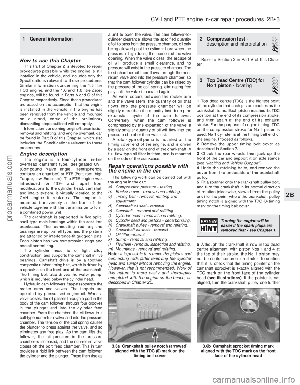
1 General information
How to use this Chapter
This Part of Chapter 2 is devoted to repair
procedures possible while the engine is still
installed in the vehicle, and includes only the
Specifications relevant to those procedures.
Similar information concerning the 1.3 litre
HCS engine, and the 1.6 and 1.8 litre Zetec
engines, will be found in Parts A and C of this
Chapter respectively. Since these procedures
are based on the assumption that the engine
is installed in the vehicle, if the engine has
been removed from the vehicle and mounted
on a stand, some of the preliminary
dismantling steps outlined will not apply.
Information concerning engine/transmission
removal and refitting, and engine overhaul, can
be found in Part D of this Chapter, which also
includes the Specifications relevant to those
procedures.
Engine description
The engine is a four-cylinder, in-line
overhead camshaft type, designated CVH
(Compound Valve angle, Hemispherical
combustion chamber) or PTE (Pent roof, high
Torque, low Emission). The PTE engine was
introduced for 1994 and, apart from
modifications to the cylinder head, camshaft
and intake system, is virtually identical to the
CVH engine it replaces. The engine is
mounted transversely at the front of the
vehicle together with the transmission to form
a combined power unit. The crankshaft is supported in five split-
shell type main bearings within the cast-iron
crankcase. The connecting rod big-end
bearings are split-shell type, and the pistons
are attached by interference-fit gudgeon pins.
Each piston has two compression rings and
one oil control ring.
The cylinder head is of light alloy
construction, and supports the camshaft in five
bearings. Camshaft drive is by a toothed
composite rubber timing belt, which is driven by
a sprocket on the front end of the crankshaft.
The timing belt also drives the water pump,
which is mounted below the cylinder head. Hydraulic cam followers (tappets) operate the
rocker arms and valves. The tappets are
operated by pressurised engine oil. When a
valve closes, the oil passes through a port in the
body of the cam follower, through four grooves
in the plunger and into the cylinder feed
chamber. From the chamber, the oil flows to a
ball-type non-return valve and into the pressure
chamber. The tension of the coil spring causes
the plunger to press against the valve, and so
eliminates any free play. As the cam lifts the
follower, the oil pressure in the pressure
chamber is increased, and the non-return valve
closes off the port feed chamber. This in turn
provides a rigid link between the cam follower,
the cylinder and the plunger. These then rise as a unit to open the valve. The cam follower-to-
cylinder clearance allows the specified quantity
of oil to pass from the pressure chamber, oil only
being allowed past the cylinder bore when the
pressure is high during the moment of the valve
opening. When the valve closes, the escape of
oil will produce a small clearance, and no
pressure will exist in the pressure chamber. The
feed chamber oil then flows through the non-
return valve and into the pressure chamber, so
that the cam follower cylinder can be raised by
the pressure of the coil spring, eliminating free
play until the valve is operated again.
As wear occurs between the rocker arm
and the valve stem, the quantity of oil that
flows into the pressure chamber will be
slightly more than the quantity lost during the
expansion cycle of the cam follower.
Conversely, when the cam follower is
compressed by the expansion of the valve, a
slightly smaller quantity of oil will flow into the
pressure chamber than was lost. A rotor-type oil pump is mounted on the
timing cover end of the engine, and is driven
by a gear on the front end of the crankshaft. A
full-flow type oil filter is fitted, and is mounted
on the side of the crankcase.
Repair operations possible with
the engine in the car
The following work can be carried out with
the engine in the car:
a) Compression pressure - testing.
b) Rocker cover - removal and refitting.
c) Timing belt - removal, refitting and
adjustment.
d) Camshaft oil seal - renewal.
e) Camshaft - removal and refitting.
f) Cylinder head - removal and refitting.
g) Cylinder head and pistons - decarbonising.
h) Crankshaft pulley - removal and refitting.
i) Crankshaft oil seals - renewal.
j) Oil filter renewal.
k) Sump - removal and refitting.
l) Flywheel - removal, inspection and refitting.
m) Mountings - removal and refitting.
Note: It is possible to remove the pistons and
connecting rods (after removing the cylinder
head and sump) without removing the engine.
However, this is not recommended. Work of
this nature is more easily and thoroughly
completed with the engine on the bench, as
described in Chapter 2D.
2 Compression test -
description and interpretation
2
Refer to Section 2 in Part A of this Chap-
ter.
3 Top Dead Centre (TDC) for
No 1 piston - locating
2
1Top dead centre (TDC) is the highest point
of the cylinder that each piston reaches as the
crankshaft turns. Each piston reaches its TDC
position at the end of its compression stroke,
and then again at the end of its exhaust
stroke. For the purpose of engine timing, TDC
on the compression stroke for No 1 piston is
used. No 1 cylinder is at the timing belt end of
the engine. Proceed as follows.
2 Remove the upper timing belt cover as
described in Section 7.
3 Chock the rear wheels then jack up the
front of the car and support it on axle stands
(see “Jacking and Vehicle Support” ).
4 Undo the retaining bolts, and remove the
cover from the underside of the crankshaft
pulley.
5 Fit a spanner onto the crankshaft pulley bolt,
and turn the crankshaft in its normal direction
of rotation (clockwise, viewed from the pulley
end) to the point where the crankshaft pulley
timing notch is aligned with the TDC (0) timing
mark on the timing belt cover.
6 Although the crankshaft is now in top dead
centre alignment, with piston Nos 1 and 4 at
the top of their stroke, the No 1 piston may
not be on its compression stroke. To confirm
that it is, check that the timing pointer on the
camshaft sprocket is exactly aligned with the
TDC mark on the front face of the cylinder
head (see illustrations) . If the pointer is not
aligned, turn the crankshaft pulley one further
CVH and PTE engine in-car repair procedures 2B•3
3.6b Camshaft sprocket timing mark
aligned with the TDC mark on the front
face of the cylinder head3.6a Crankshaft pulley notch (arrowed)aligned with the TDC (0) mark on the
timing belt cover
2B
1595Ford Fiesta Remake
Turning the engine will be
easier if the spark plugs are
removed first - see Chapter 1.
procarmanuals.com
http://vnx.su