1989 FORD FIESTA Weekly checks
[x] Cancel search: Weekly checksPage 121 of 296
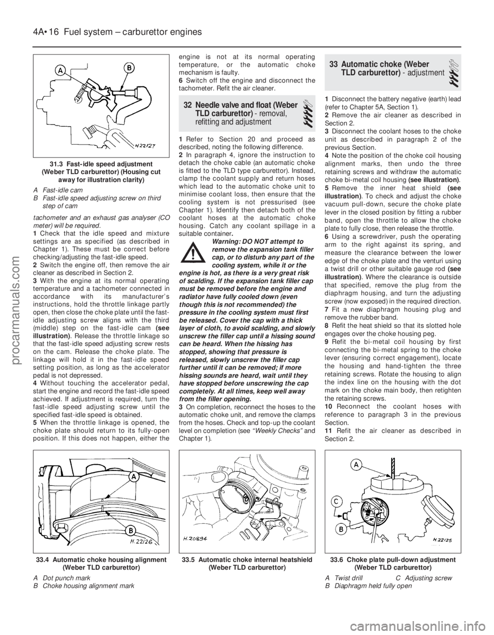
tachometer and an exhaust gas analyser (CO
meter) will be required.
1Check that the idle speed and mixture
settings are as specified (as described in
Chapter 1). These must be correct before
checking/adjusting the fast-idle speed.
2 Switch the engine off, then remove the air
cleaner as described in Section 2.
3 With the engine at its normal operating
temperature and a tachometer connected in
accordance with its manufacturer’s
instructions, hold the throttle linkage partly
open, then close the choke plate until the fast-
idle adjusting screw aligns with the third
(middle) step on the fast-idle cam (see
illustration) . Release the throttle linkage so
that the fast-idle speed adjusting screw rests
on the cam. Release the choke plate. The
linkage will hold it in the fast-idle speed
setting position, as long as the accelerator
pedal is not depressed.
4 Without touching the accelerator pedal,
start the engine and record the fast-idle speed
achieved. If adjustment is required, turn the
fast-idle speed adjusting screw until the
specified fast-idle speed is obtained.
5 When the throttle linkage is opened, the
choke plate should return to its fully-open
position. If this does not happen, either the engine is not at its normal operating
temperature, or the automatic choke
mechanism is faulty.
6
Switch off the engine and disconnect the
tachometer. Refit the air cleaner.
32 Needle valve and float (Weber
TLD carburettor) - removal,
refitting and adjustment
4
1 Refer to Section 20 and proceed as
described, noting the following difference.
2 In paragraph 4, ignore the instruction to
detach the choke cable (an automatic choke
is fitted to the TLD type carburettor). Instead,
clamp the coolant supply and return hoses
which lead to the automatic choke unit to
minimise coolant loss, then ensure that the
cooling system is not pressurised (see
Chapter 1). Identify then detach both of the
coolant hoses at the automatic choke
housing. Catch any coolant spillage in a
suitable container .
Warning: DO NOT attempt to
remove the expansion tank filler
cap, or to disturb any part of the
cooling system, while it or the
engine is hot, as there is a very great risk
of scalding. If the expansion tank filler cap
must be removed before the engine and
radiator have fully cooled down (even
though this is not recommended) the
pressure in the cooling system must first
be released. Cover the cap with a thick
layer of cloth, to avoid scalding, and slowly
unscrew the filler cap until a hissing sound
can be heard. When the hissing has
stopped, showing that pressure is
released, slowly unscrew the filler cap
further until it can be removed; if more
hissing sounds are heard, wait until they
have stopped before unscrewing the cap
completely. At all times, keep well away
from the filler opening.
3 On completion, reconnect the hoses to the
automatic choke unit, and remove the clamps
from the hoses. Check and top-up the coolant
level on completion (see “Weekly Checks”and
Chapter 1).
33 Automatic choke (Weber TLD carburettor) - adjustment
3
1Disconnect the battery negative (earth) lead
(refer to Chapter 5A, Section 1).
2 Remove the air cleaner as described in
Section 2.
3 Disconnect the coolant hoses to the choke
unit as described in paragraph 2 of the
previous Section.
4 Note the position of the choke coil housing
alignment marks, then undo the three
retaining screws and withdraw the automatic
choke bi-metal coil housing (see illustration).
5 Remove the inner heat shield (see
illustration) . To check and adjust the choke
vacuum pull-down, secure the choke plate
lever in the closed position by fitting a rubber
band, open the throttle to allow the choke
plate to fully close, then release the throttle.
6 Using a screwdriver, push the operating
arm to the right against its spring, and
measure the clearance between the lower
edge of the choke plate and the venturi using
a twist drill or other suitable gauge rod (see
illustration) . Where the clearance is outside
that specified, remove the plug from the
diaphragm housing, and turn the adjusting
screw (now exposed) in the required direction.
7 Fit a new diaphragm housing plug and
remove the rubber band.
8 Refit the heat shield so that its slotted hole
engages over the choke housing peg.
9 Refit the bi-metal coil housing by first
connecting the bi-metal spring to the choke
lever (ensuring correct engagement), locate
the housing and hand-tighten the three
retaining screws. Rotate the housing to align
the index line on the housing with the dot
mark on the choke main body, then retighten
the retaining screws.
10 Reconnect the coolant hoses with
reference to paragraph 3 in the previous
Section.
11 Refit the air cleaner as described in
Section 2.
4A•16 Fuel system – carburettor engines
33.6 Choke plate pull-down adjustment (Weber TLD carburettor)
A Twist drill C Adjusting screw
B Diaphragm held fully open33.5 Automatic choke internal heatshield (Weber TLD carburettor)33.4 Automatic choke housing alignment(Weber TLD carburettor)
A Dot punch mark
B Choke housing alignment mark
1595Ford Fiesta Remake
31.3 Fast-idle speed adjustment
(Weber TLD carburettor) (Housing cut away for illustration clarity)
A Fast-idle cam
B Fast-idle speed adjusting screw on third step of cam
procarmanuals.com
http://vnx.su
Page 122 of 296
34 Automatic choke (WeberTLD carburettor) - removal,
inspection and refitting
4
Note: Refer to the warning note in Section 1
before proceeding. A new carburettor upper
body gasket will be required when
reassembling. On completion, a tachometer
will be required to check the fast-idle speed
adjustment.
Removal
1 Disconnect the battery negative (earth) lead
(refer to Chapter 5A, Section 1).
2 Remove the air cleaner as described in
Section 2.
3 To prevent excess coolant loss, clamp the
coolant supply and return hoses to the
automatic choke unit, and ensure that the
cooling system is not pressurised (see
Chapter 1). Identify then detach both of the
coolant hoses at the automatic choke
housing. Catch any coolant spillage in a
suitable container.
Warning: DO NOT attempt to
remove the expansion tank filler
cap, or to disturb any part of the
cooling system, while it or the
engine is hot, as there is a very great risk
of scalding. If the expansion tank filler cap
must be removed before the engine and
radiator have fully cooled down (even
though this is not recommended) the
pressure in the cooling system must first
be released. Cover the cap with a thick
layer of cloth, to avoid scalding, and slowly
unscrew the filler cap until a hissing sound
can be heard. When the hissing has
stopped, showing that pressure is
released, slowly unscrew the filler cap
further until it can be removed; if more
hissing sounds are heard, wait until they
have stopped before unscrewing the cap
completely. At all times, keep well away
from the filler opening.
4 Detach the fuel pipe and the anti-dieseling
solenoid wiring connector. Any crimped type
hose clips must be replaced with a screw
clamp type clips during reassembly.
5 Unscrew and remove the retaining screws (two conventional, and four Torx type), then lift
the carburettor upper body clear and remove it.
6
Note the position of the choke housing
alignment marks, then undo the three retaining
screws and remove the choke bi-metal coil
unit. Remove the internal heat shield.
7 To remove the automatic choke unit, undo
the three retaining screws and detach the
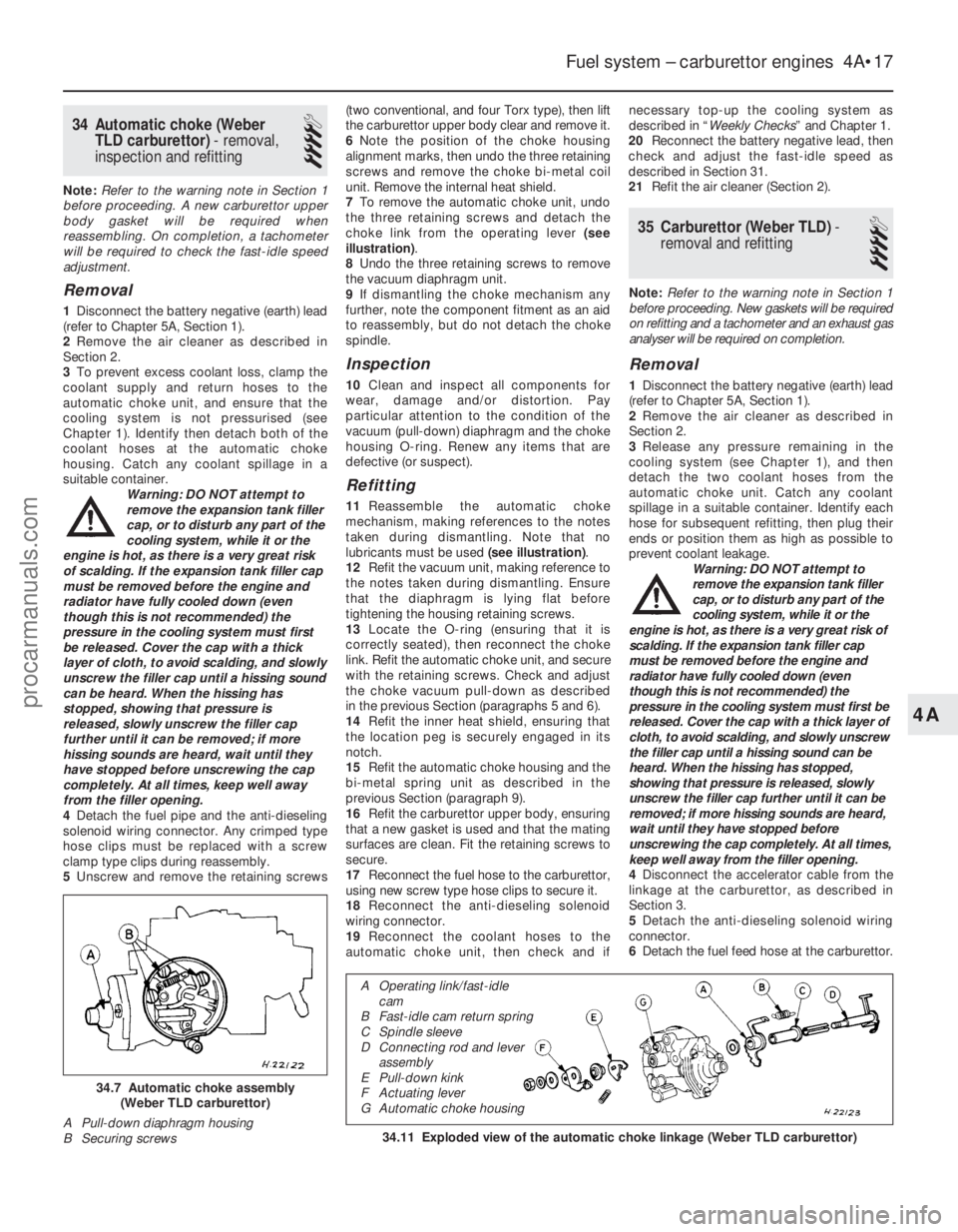
choke link from the operating lever (see
illustration) .
8 Undo the three retaining screws to remove
the vacuum diaphragm unit.
9 If dismantling the choke mechanism any
further, note the component fitment as an aid
to reassembly, but do not detach the choke
spindle.
Inspection
10 Clean and inspect all components for
wear, damage and/or distortion. Pay
particular attention to the condition of the
vacuum (pull-down) diaphragm and the choke
housing O-ring. Renew any items that are
defective (or suspect).
Refitting
11 Reassemble the automatic choke
mechanism, making references to the notes
taken during dismantling. Note that no
lubricants must be used (see illustration).
12 Refit the vacuum unit, making reference to
the notes taken during dismantling. Ensure
that the diaphragm is lying flat before
tightening the housing retaining screws.
13 Locate the O-ring (ensuring that it is
correctly seated), then reconnect the choke
link. Refit the automatic choke unit, and secure
with the retaining screws. Check and adjust
the choke vacuum pull-down as described
in the previous Section (paragraphs 5 and 6).
14 Refit the inner heat shield, ensuring that
the location peg is securely engaged in its
notch.
15 Refit the automatic choke housing and the
bi-metal spring unit as described in the
previous Section (paragraph 9).
16 Refit the carburettor upper body, ensuring
that a new gasket is used and that the mating
surfaces are clean. Fit the retaining screws to
secure.
17 Reconnect the fuel hose to the carburettor,
using new screw type hose clips to secure it.
18 Reconnect the anti-dieseling solenoid
wiring connector.
19 Reconnect the coolant hoses to the
automatic choke unit, then check and if necessary top-up the cooling system as
described in “
Weekly Checks ” and Chapter 1.
20 Reconnect the battery negative lead, then
check and adjust the fast-idle speed as
described in Section 31.
21 Refit the air cleaner (Section 2).
35 Carburettor (Weber TLD) -
removal and refitting
4
Note: Refer to the warning note in Section 1
before proceeding. New gaskets will be required
on refitting and a tachometer and an exhaust gas
analyser will be required on completion.
Removal
1 Disconnect the battery negative (earth) lead
(refer to Chapter 5A, Section 1).
2 Remove the air cleaner as described in
Section 2.
3 Release any pressure remaining in the
cooling system (see Chapter 1), and then
detach the two coolant hoses from the
automatic choke unit. Catch any coolant
spillage in a suitable container. Identify each
hose for subsequent refitting, then plug their
ends or position them as high as possible to
prevent coolant leakage. Warning: DO NOT attempt to
remove the expansion tank filler
cap, or to disturb any part of the
cooling system, while it or the
engine is hot, as there is a very great risk of
scalding. If the expansion tank filler cap
must be removed before the engine and
radiator have fully cooled down (even
though this is not recommended) the
pressure in the cooling system must first be
released. Cover the cap with a thick layer of
cloth, to avoid scalding, and slowly unscrew
the filler cap until a hissing sound can be
heard. When the hissing has stopped,
showing that pressure is released, slowly
unscrew the filler cap further until it can be
removed; if more hissing sounds are heard,
wait until they have stopped before
unscrewing the cap completely. At all times,
keep well away from the filler opening.
4 Disconnect the accelerator cable from the
linkage at the carburettor, as described in
Section 3.
5 Detach the anti-dieseling solenoid wiring
connector.
6 Detach the fuel feed hose at the carburettor.
Fuel system – carburettor engines 4A•17
34.11 Exploded view of the automatic choke linkage (Weber TLD carburet\
tor)
34.7 Automatic choke assembly
(Weber TLD carburettor)
A Pull-down diaphragm housing
B Securing screws
4A
1595Ford Fiesta Remake
A Operating link/fast-idle cam
B Fast-idle cam return spring
C Spindle sleeve
D Connecting rod and lever assembly
E Pull-down kink
F Actuating lever
G Automatic choke housing
procarmanuals.com
http://vnx.su
Page 123 of 296
As it is detached, plug the end of the hose to
prevent excessive fuel spillage and the ingress
of dirt. Where a crimped type hose clip is fitted,
cut it free, taking care not to damage the hose;
a new screw type clip will need to be obtained
to replace the crimped clip during reassembly.
7Disconnect the relevant vacuum pipes from
the carburettor. As they are detached, label
them to ensure correct reassembly.
8 Unscrew and remove the four Torx-type
retaining screws, and carefully lift clear the
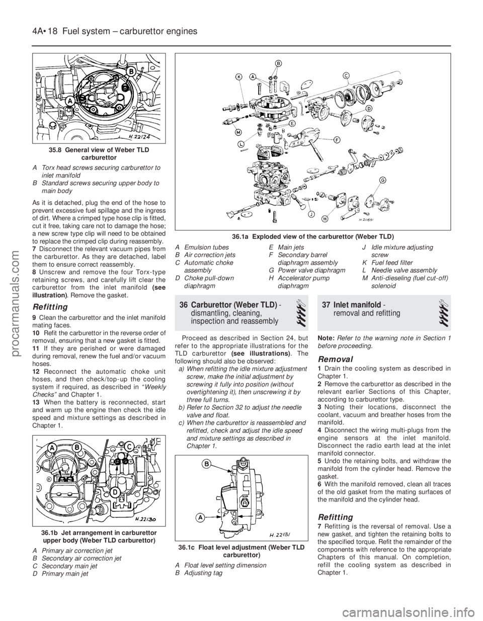
carburettor from the inlet manifold (see
illustration) . Remove the gasket.
Refitting
9Clean the carburettor and the inlet manifold
mating faces.
10 Refit the carburettor in the reverse order of
removal, ensuring that a new gasket is fitted.
11 If they are perished or were damaged
during removal, renew the fuel and/or vacuum
hoses.
12 Reconnect the automatic choke unit
hoses, and then check/top-up the cooling
system if required, as described in “Weekly
Checks” and Chapter 1.
13 When the battery is reconnected, start
and warm up the engine then check the idle
speed and mixture settings as described in
Chapter 1.
36 Carburettor (Weber TLD) -
dismantling, cleaning,
inspection and reassembly
4
Proceed as described in Section 24, but
refer to the appropriate illustrations for the
TLD carburettor (see illustrations) . The
following should also be observed: a) When refitting the idle mixture adjustment
screw, make the initial adjustment by
screwing it fully into position (without
overtightening it), then unscrewing it by
three full turns.
b) Refer to Section 32 to adjust the needle
valve and float.
c) When the carburettor is reassembled and refitted, check and adjust the idle speed
and mixture settings as described in
Chapter 1.
37 Inlet manifold -
removal and refitting
4
Note: Refer to the warning note in Section 1
before proceeding.
Removal
1 Drain the cooling system as described in
Chapter 1.
2 Remove the carburettor as described in the
relevant earlier Sections of this Chapter,
according to carburettor type.
3 Noting their locations, disconnect the
coolant, vacuum and breather hoses from the
manifold.
4 Disconnect the wiring multi-plugs from the
engine sensors at the inlet manifold.
Disconnect the radio earth lead at the inlet
manifold connector.
5 Undo the retaining bolts, and withdraw the
manifold from the cylinder head. Remove the
gasket.
6 With the manifold removed, clean all traces
of the old gasket from the mating surfaces of
the manifold and the cylinder head.
Refitting
7 Refitting is the reversal of removal. Use a
new gasket, and tighten the retaining bolts to
the specified torque. Refit the remainder of the
components with reference to the appropriate
Chapters of this manual. On completion,
refill the cooling system as described in
Chapter 1.
36.1c Float level adjustment (Weber TLD carburettor)
A Float level setting dimension
B Adjusting tag
36.1b Jet arrangement in carburettor upper body (Weber TLD carburettor)
A Primary air correction jet
B Secondary air correction jet
C Secondary main jet
D Primary main jet
4A•18 Fuel system – carburettor engines
36.1a Exploded view of the carburettor (Weber TLD)
A Emulsion tubes
B Air correction jets
C Automatic choke assembly
D Choke pull-down
diaphragm E Main jets
F Secondary barrel
diaphragm assembly
G Power valve diaphragm
H Accelerator pump
diaphragm J Idle mixture adjusting
screw
K Fuel feed filter
L Needle valve assembly
M Anti-dieseling (fuel cut-off) solenoid
35.8 General view of Weber TLD carburettor
A Torx head screws securing carburettor to inlet manifold
B Standard screws securing upper body to main body
1595Ford Fiesta Remakeprocarmanuals.com
http://vnx.su
Page 130 of 296
21Disconnect the vacuum hose from the CFi
unit.
22 Unscrew and remove the four retaining
screws, and remove the CFi unit from the inlet
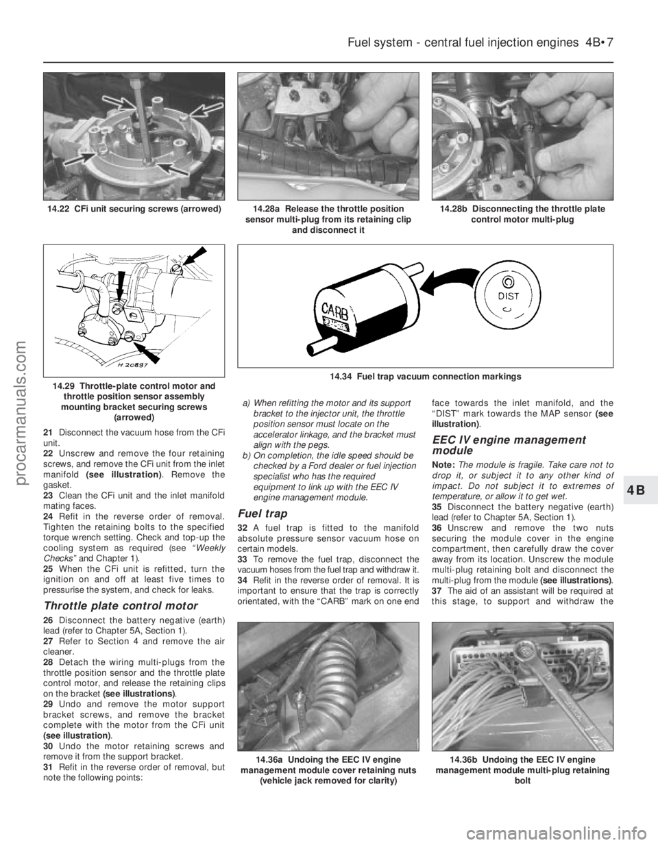
manifold (see illustration) . Remove the
gasket.
23 Clean the CFi unit and the inlet manifold
mating faces.
24 Refit in the reverse order of removal.
Tighten the retaining bolts to the specified
torque wrench setting. Check and top-up the
cooling system as required (see “Weekly
Checks” and Chapter 1).
25 When the CFi unit is refitted, turn the
ignition on and off at least five times to
pressurise the system, and check for leaks.
Throttle plate control motor
26 Disconnect the battery negative (earth)
lead (refer to Chapter 5A, Section 1).
27 Refer to Section 4 and remove the air
cleaner.
28 Detach the wiring multi-plugs from the
throttle position sensor and the throttle plate
control motor, and release the retaining clips
on the bracket (see illustrations) .
29 Undo and remove the motor support
bracket screws, and remove the bracket
complete with the motor from the CFi unit
(see illustration) .
30 Undo the motor retaining screws and
remove it from the support bracket.
31 Refit in the reverse order of removal, but
note the following points: a) When refitting the motor and its support
bracket to the injector unit, the throttle
position sensor must locate on the
accelerator linkage, and the bracket must
align with the pegs.
b) On completion, the idle speed should be
checked by a Ford dealer or fuel injection
specialist who has the required
equipment to link up with the EEC IV
engine management module.
Fuel trap
32 A fuel trap is fitted to the manifold
absolute pressure sensor vacuum hose on
certain models.
33 To remove the fuel trap, disconnect the
vacuum hoses from the fuel trap and withdraw it.
34 Refit in the reverse order of removal. It is
important to ensure that the trap is correctly
orientated, with the “CARB” mark on one end face towards the inlet manifold, and the
“DIST” mark towards the MAP sensor
(see
illustration) .
EEC IV engine management
module
Note: The module is fragile. Take care not to
drop it, or subject it to any other kind of
impact. Do not subject it to extremes of
temperature, or allow it to get wet.
35 Disconnect the battery negative (earth)
lead (refer to Chapter 5A, Section 1).
36 Unscrew and remove the two nuts
securing the module cover in the engine
compartment, then carefully draw the cover
away from its location. Unscrew the module
multi-plug retaining bolt and disconnect the
multi-plug from the module (see illustrations).
37 The aid of an assistant will be required at
this stage, to support and withdraw the
Fuel system - central fuel injection engines 4B•7
14.28b Disconnecting the throttle plate control motor multi-plug14.28a Release the throttle position
sensor multi-plug from its retaining clip and disconnect it14.22 CFi unit securing screws (arrowed)
14.36b Undoing the EEC IV engine
management module multi-plug retaining
bolt
14.34 Fuel trap vacuum connection markings14.29 Throttle-plate control motor andthrottle position sensor assembly
mounting bracket securing screws (arrowed)
14.36a Undoing the EEC IV engine
management module cover retaining nuts
(vehicle jack removed for clarity)
4B
1595Ford Fiesta Remakeprocarmanuals.com
http://vnx.su
Page 131 of 296
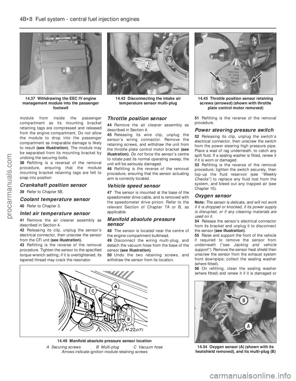
module from inside the passenger
compartment as its mounting bracket
retaining tags are compressed and released
from the engine compartment. Do not allow
the module to drop into the passenger
compartment as irreparable damage is likely
to result (see illustration) . The module may
be separated from its mounting bracket by
undoing the securing bolts.
38 Refitting is a reversal of the removal
procedure, ensuring that the module
mounting bracket retaining tags are felt to
snap into position
Crankshaft position sensor
39 Refer to Chapter 5B.
Coolant temperature sensor
40Refer to Chapter 3.
Inlet air temperature sensor
41Remove the air cleaner assembly as
described in Section 4.
42 Releasing its clip, unplug the sensor’s
electrical connector, then unscrew the sensor
from the CFi unit (see illustration).
43 Refitting is the reverse of the removal
procedure. Tighten the sensor to the specified
torque wrench setting; if it is overtightened, its
tapered thread may crack the resonator.
Throttle position sensor
44 Remove the air cleaner assembly as
described in Section 4.
45 Releasing its wire clip, unplug the
sensor’s wiring connector. Remove the
retaining screws, and withdraw the unit from
the throttle plate control motor bracket (see
illustration) . Do not force the sensor’s centre
to rotate past its normal operating sweep; the
unit will be seriously damaged.
46 Refitting is the reverse of the removal
procedure, ensuring that the sensor actuating
arm is correctly located.
Vehicle speed sensor
47 The sensor is mounted at the base of the
speedometer drive cable, and is removed with
the speedometer drive pinion. Refer to the
relevant Section of Chapter 7A or B, as
applicable.
Manifold absolute pressure
sensor
48 The sensor is located near the centre of
the engine compartment bulkhead.
49 Disconnect the wiring multi-plug, and
detach the vacuum hose from the base of the
sensor (see illustration) .
50 Undo the two retaining screws, and
withdraw the sensor from its location. 51
Refitting is the reverse of the removal
procedure.
Power steering pressure switch
52 Releasing its clip, unplug the switch’s
electrical connector, then unscrew the switch
from the power steering high pressure pipe.
Place a wad of rag underneath, to catch any
spilt fluid. If a sealing washer is fitted, renew it
if it is worn or damaged.
53 Refitting is the reverse of the removal
procedure; tighten the switch securely, then
top-up the fluid reservoir (see “Weekly
Checks” ) to replace any fluid lost from the
system, and bleed out any trapped air (see
Chapter 10).
Oxygen sensor
Note: The sensor is delicate, and will not work
if it is dropped or knocked, if its power supply
is disrupted, or if any cleaning materials are
used on it.
54 Release the sensor’s electrical connector
from its bracket and unplug it to disconnect
the sensor (see illustration) .
55 Raise and support the front of the vehicle
if required to remove the sensor from
underneath (“see Jacking and vehicle
support” ). Remove the sensor heat shield then
unscrew the sensor from the exhaust system
front downpipe; collect the sealing washer
(where fitted).
56 On refitting, clean the sealing washer
(where fitted) and renew it if it is damaged or
4B•8 Fuel system - central fuel injection engines
14.54 Oxygen sensor (A) (shown with its
heatshield removed), and its multi-plug (B)
14.49 Manifold absolute pressure sensor location
A Securing screws B Multi-plug C Vacuum hose\
Arrows indicate ignition module retaining screws
14.45 Throttle position sensor retainingscrews (arrowed) (shown with throttle plate control motor removed)14.42 Disconnecting the intake airtemperature sensor multi-plug
1595Ford Fiesta Remake
14.37 Withdrawing the EEC IV engine
management module into the passenger footwellprocarmanuals.com
http://vnx.su
Page 140 of 296
Crankshaft position sensor
40Refer to Chapter 5B.
Coolant temperature sensor
41Refer to Chapter 3.
Inlet air temperature sensor
42Remove the air inlet components as
described in Section 4.
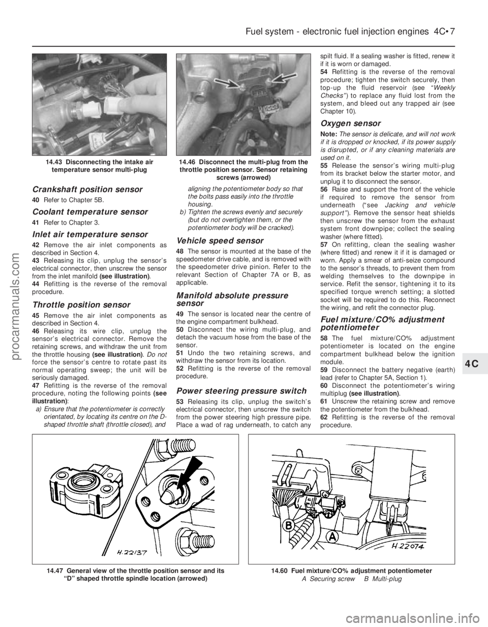
43 Releasing its clip, unplug the sensor’s
electrical connector, then unscrew the sensor
from the inlet manifold (see illustration).
44 Refitting is the reverse of the removal
procedure.
Throttle position sensor
45 Remove the air inlet components as
described in Section 4.
46 Releasing its wire clip, unplug the
sensor’s electrical connector. Remove the
retaining screws, and withdraw the unit from
the throttle housing (see illustration). Do not
force the sensor’s centre to rotate past its
normal operating sweep; the unit will be
seriously damaged.
47 Refitting is the reverse of the removal
procedure, noting the following points (see
illustration) :
a) Ensure that the potentiometer is correctly
orientated, by locating its centre on the D-
shaped throttle shaft (throttle closed), and aligning the potentiometer body so that
the bolts pass easily into the throttle
housing.
b) Tighten the screws evenly and securely
(but do not overtighten them, or the
potentiometer body will be cracked).
Vehicle speed sensor
48 The sensor is mounted at the base of the
speedometer drive cable, and is removed with
the speedometer drive pinion. Refer to the
relevant Section of Chapter 7A or B, as
applicable.
Manifold absolute pressure
sensor
49 The sensor is located near the centre of
the engine compartment bulkhead.
50 Disconnect the wiring multi-plug, and
detach the vacuum hose from the base of the
sensor.
51 Undo the two retaining screws, and
withdraw the sensor from its location.
52 Refitting is the reverse of the removal
procedure.
Power steering pressure switch
53 Releasing its clip, unplug the switch’s
electrical connector, then unscrew the switch
from the power steering high pressure pipe.
Place a wad of rag underneath, to catch any spilt fluid. If a sealing washer is fitted, renew it
if it is worn or damaged.
54
Refitting is the reverse of the removal
procedure; tighten the switch securely, then
top-up the fluid reservoir (see “Weekly
Checks” ) to replace any fluid lost from the
system, and bleed out any trapped air (see
Chapter 10).
Oxygen sensor
Note: The sensor is delicate, and will not work
if it is dropped or knocked, if its power supply
is disrupted, or if any cleaning materials are
used on it.
55 Release the sensor’s wiring multi-plug
from its bracket below the starter motor, and
unplug it to disconnect the sensor.
56 Raise and support the front of the vehicle
if required to remove the sensor from
underneath (“see Jacking and vehicle
support” ). Remove the sensor heat shields
then unscrew the sensor from the exhaust
system front downpipe; collect the sealing
washer (where fitted).
57 On refitting, clean the sealing washer
(where fitted) and renew it if it is damaged or
worn. Apply a smear of anti-seize compound
to the sensor’s threads, to prevent them from
welding themselves to the downpipe in
service. Refit the sensor, tightening it to its
specified torque wrench setting; a slotted
socket will be required to do this. Reconnect
the wiring, and refit the connector plug.
Fuel mixture/CO% adjustment
potentiometer
58 The fuel mixture/CO% adjustment
potentiometer is located on the engine
compartment bulkhead below the ignition
module.
59 Disconnect the battery negative (earth)
lead (refer to Chapter 5A, Section 1).
60 Disconnect the potentiometer’s wiring
multiplug (see illustration) .
61 Unscrew the retaining screw and remove
the potentiometer from the bulkhead.
62 Refitting is the reverse of the removal
procedure.
Fuel system - electronic fuel injection engines 4C•7
14.46 Disconnect the multi-plug from the throttle position sensor. Sensor retaining screws (arrowed)14.43 Disconnecting the intake airtemperature sensor multi-plug
14.60 Fuel mixture/CO% adjustment potentiometer
A Securing screw B Multi-plug14.47 General view of the throttle position sensor and its “D” shaped throttle spindle location (arrowed)
4C
1595Ford Fiesta Remakeprocarmanuals.com
http://vnx.su
Page 150 of 296
b)Tighten the screws evenly and securely
(but do not overtighten them, or the
potentiometer body will be cracked).
Vehicle speed sensor
48 The sensor is mounted at the base of the
speedometer drive cable, and is removed with
the speedometer drive pinion. Refer to the
relevant Section of Chapter 7A or B, as
applicable.
Power steering pressure switch
49 Releasing its clip, unplug the switch’s
electrical connector, then unscrew the switch
from the power steering high pressure pipe.
Place a wad of rag underneath, to catch any
spilt fluid. If a sealing washer is fitted, renew it
if it is worn or damaged.
50 Refitting is the reverse of the removal
procedure; tighten the switch securely, then
top-up the fluid reservoir (see “Weekly
Checks”) to replace any fluid lost from the
system, and bleed out any trapped air (see
Chapter 10).
Oxygen sensor
Note: The sensor is delicate, and will not work
if it is dropped or knocked, if its power supply
is disrupted, or if any cleaning materials are
used on it.
51 Raise and support the front of the vehicle
if required to remove the sensor from
underneath (“see Jacking and vehicle
support” ).
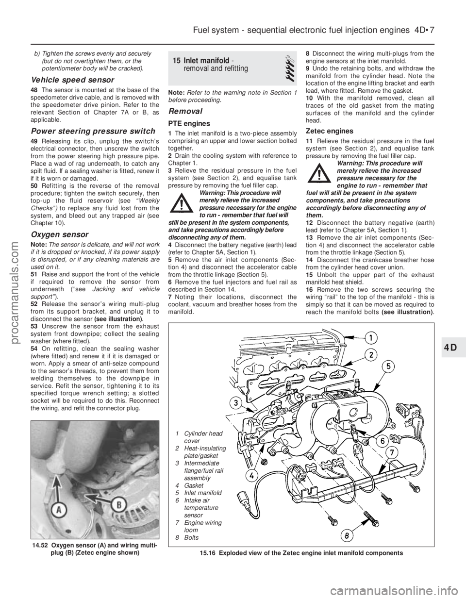
52 Release the sensor’s wiring multi-plug
from its support bracket, and unplug it to
disconnect the sensor (see illustration).
53 Unscrew the sensor from the exhaust
system front downpipe; collect the sealing
washer (where fitted).
54 On refitting, clean the sealing washer
(where fitted) and renew it if it is damaged or
worn. Apply a smear of anti-seize compound
to the sensor’s threads, to prevent them from
welding themselves to the downpipe in
service. Refit the sensor, tightening it to its
specified torque wrench setting; a slotted
socket will be required to do this. Reconnect
the wiring, and refit the connector plug.
15 Inlet manifold -
removal and refitting
4
Note: Refer to the warning note in Section 1
before proceeding.
Removal
PTE engines
1 The inlet manifold is a two-piece assembly
comprising an upper and lower section bolted
together.
2 Drain the cooling system with reference to
Chapter 1.
3 Relieve the residual pressure in the fuel
system (see Section 2), and equalise tank
pressure by removing the fuel filler cap. Warning: This procedure will
merely relieve the increased
pressure necessary for the engine
to run - remember that fuel will
still be present in the system components,
and take precautions accordingly before
disconnecting any of them.
4 Disconnect the battery negative (earth) lead
(refer to Chapter 5A, Section 1).
5 Remove the air inlet components (Sec-
tion 4) and disconnect the accelerator cable
from the throttle linkage (Section 5).
6 Remove the fuel injectors and fuel rail as
described in Section 14.
7 Noting their locations, disconnect the
coolant, vacuum and breather hoses from the
manifold. 8
Disconnect the wiring multi-plugs from the
engine sensors at the inlet manifold.
9 Undo the retaining bolts, and withdraw the
manifold from the cylinder head. Note the
location of the engine lifting bracket and earth
lead, where fitted. Remove the gasket.
10 With the manifold removed, clean all
traces of the old gasket from the mating
surfaces of the manifold and the cylinder
head.Zetec engines
11 Relieve the residual pressure in the fuel
system (see Section 2), and equalise tank
pressure by removing the fuel filler cap. Warning: This procedure will
merely relieve the increased
pressure necessary for the
engine to run - remember that
fuel will still be present in the system
components, and take precautions
accordingly before disconnecting any of
them.
12 Disconnect the battery negative (earth)
lead (refer to Chapter 5A, Section 1).
13 Remove the air inlet components (Sec-
tion 4) and disconnect the accelerator cable
from the throttle linkage (Section 5).
14 Disconnect the crankcase breather hose
from the cylinder head cover union.
15 Unbolt the upper part of the exhaust
manifold heat shield.
16 Remove the two screws securing the
wiring “rail” to the top of the manifold - this is
simply so that it can be moved as required to
reach the manifold bolts (see illustration).
Fuel system - sequential electronic fuel injection engines 4D•7
14.52 Oxygen sensor (A) and wiring multi-
plug (B) (Zetec engine shown)15.16 Exploded view of the Zetec engine inlet manifold components
4D
1595Ford Fiesta Remake
1 Cylinder head
cover
2 Heat-insulating plate/gasket
3 Intermediate flange/fuel rail
assembly
4 Gasket
5 Inlet manifold
6 Intake air temperature
sensor
7 Engine wiring
loom
8 Boltsprocarmanuals.com
http://vnx.su
Page 160 of 296
5A
1595Ford Fiesta Remake
General
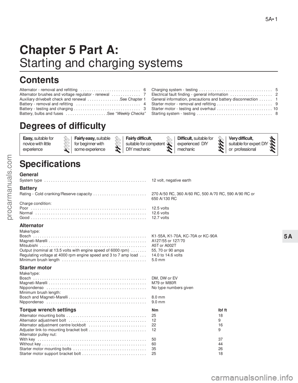
System type . . . . . . . . . . . . . . . . . . . . . . . . . . . . . . . . . . . .\
. . . . . . . . . . 12 volt, negative earth
Battery
Rating - Cold cranking/Reserve capacity . . . . . . . . . . . . . . . . . . . . . . . . 270 A/50 RC, 360 A/60 RC, 500 A/70 RC, 590 A/90 RC or 650 A/130 RC
Charge condition:
Poor . . . . . . . . . . . . . . . . . . . . . . . . . . . . . . . . . . . .\
. . . . . . . . . . . . . . . . 12.5 volts
Normal . . . . . . . . . . . . . . . . . . . . . . . . . . . . . . . . . . . .\
. . . . . . . . . . . . . . 12.6 volts
Good . . . . . . . . . . . . . . . . . . . . . . . . . . . . . . . . . . . .\
. . . . . . . . . . . . . . . . 12.7 volts
Alternator
Make/type:
Bosch . . . . . . . . . . . . . . . . . . . . . . . . . . . . . . . . . . . .\
. . . . . . . . . . . . . . . K1-55A, K1-70A, KC-70A or KC-90A
Magneti-Marelli . . . . . . . . . . . . . . . . . . . . . . . . . . . . . . . . . . . .\
. . . . . . . . A127/55 or 127/70
Mitsubishi . . . . . . . . . . . . . . . . . . . . . . . . . . . . . . . . . . . .\
. . . . . . . . . . . . A5T or A002T
Output (nominal at 13.5 volts with engine speed of 6000 rpm) . . . . . . . 55, 70 or 90 amps
Regulating voltage at 4000 rpm engine speed and 3 to 7 amp load . . . 14.0 to 14.6 volts
Minimum brush length . . . . . . . . . . . . . . . . . . . . . . . . . . . . . . . . . . . .\
. . 5.0 mm
Starter motor
Make/type:
Bosch . . . . . . . . . . . . . . . . . . . . . . . . . . . . . . . . . . . .\
. . . . . . . . . . . . . . . DM, DW or EV
Magneti-Marelli . . . . . . . . . . . . . . . . . . . . . . . . . . . . . . . . . . . .\
. . . . . . . . M79 or M80R
Nippondenso . . . . . . . . . . . . . . . . . . . . . . . . . . . . . . . . . . . .\
. . . . . . . . . No type numbers given
Minimum brush length:
Bosch and Magneti-Marelli . . . . . . . . . . . . . . . . . . . . . . . . . . . . . . . . . . . 8.0 mm
Nippondenso . . . . . . . . . . . . . . . . . . . . . . . . . . . . . . . . . . . .\
. . . . . . . . . 9.0 mm
Torque wrench settingsNm lbf ft
Alternator mounting bolts . . . . . . . . . . . . . . . . . . . . . . . . . . . . . . . . . . . .\
25 18
Alternator adjustment bolt . . . . . . . . . . . . . . . . . . . . . . . . . . . . . . . . . . . 12 9
Alternator adjustment centre lockbolt . . . . . . . . . . . . . . . . . . . . . . . . . . 22 16
Adjuster link-to-mounting bracket bolt . . . . . . . . . . . . . . . . . . . . . . . . . . 12 9
Alternator pulley nut:
With key . . . . . . . . . . . . . . . . . . . . . . . . . . . . . . . . . . . .\
. . . . . . . . . . . . . 50 37
Without key . . . . . . . . . . . . . . . . . . . . . . . . . . . . . . . . . . . .\
. . . . . . . . . . . 60 44
Starter motor mounting bolts . . . . . . . . . . . . . . . . . . . . . . . . . . . . . . . . . 35 26
Starter motor support bracket bolt . . . . . . . . . . . . . . . . . . . . . . . . . . . . . 25 18
Chapter 5 Part A:
Starting and charging systems
Alternator - removal and refitting . . . . . . . . . . . . . . . . . . . . . . . . . . . 6
Alternator brushes and voltage regulator - renewal . . . . . . . . . . . . . 7
Auxiliary drivebelt check and renewal . . . . . . . . . . . . . . .See Chapter 1
Battery - removal and refitting . . . . . . . . . . . . . . . . . . . . . . . . . . . . . 4
Battery - testing and charging . . . . . . . . . . . . . . . . . . . . . . . . . . . . . . 3
Battery, bulbs and fuses . . . . . . . . . . . . . . . . . . .See
“Weekly Checks” Charging system - testing . . . . . . . . . . . . . . . . . . . . . . . . . . . . . . . . . 5
Electrical fault finding - general information . . . . . . . . . . . . . . . . . . . 2
General information, precautions and battery disconnection . . . . . . 1
Starter motor - removal and refitting . . . . . . . . . . . . . . . . . . . . . . . . . 9
Starter motor - testing and overhaul . . . . . . . . . . . . . . . . . . . . . . . . . 10
Starting system - testing . . . . . . . . . . . . . . . . . . . . . . . . . . . . . . . . . . 8
5A•1
Specifications Contents
Easy,
suitable for
novice with little
experience Fairly easy,
suitable
for beginner with
some experience Fairly difficult,
suitable for competent
DIY mechanic
Difficult,
suitable for
experienced DIY
mechanic Very difficult,
suitable for expert DIY
or professional
Degrees of difficulty
54321
procarmanuals.com
http://vnx.su