1989 FORD FIESTA tyre pressure
[x] Cancel search: tyre pressurePage 186 of 296
Bleeding - using a pressure-
bleeding kit
24These kits are usually operated by the
reservoir of pressurised air contained in the
spare tyre. However, note that it will probably
be necessary to reduce the pressure to a
lower level than normal; refer to the
instructions supplied with the kit.
25 By connecting a pressurised, fluid-filled
container to the master cylinder reservoir,
bleeding can be carried out simply by opening
each screw in turn (in the specified sequence),
and allowing the fluid to flow out until no more
air bubbles can be seen in the expelled fluid.
26 This method has the advantage that the
large reservoir of fluid provides an additional
safeguard against air being drawn into the
system during bleeding.
27 Pressure-bleeding is particularly effective
when bleeding “difficult” systems, or when
bleeding the complete system at the time of
routine fluid renewal.
All methods
28 When bleeding is complete, and firm
pedal feel is restored, wash off any spilt fluid,
tighten the bleed screws securely, and refit
their dust caps.
29 Check the hydraulic fluid level in the
master cylinder reservoir, and top-up if
necessary.
30 Discard any hydraulic fluid that has been
bled from the system; it will not be fit for re-
use.
31 Check the feel of the brake pedal. If it
feels at all spongy, air must still be present in
the system, and further bleeding is required.
Failure to bleed satisfactorily after a
reasonable repetition of the bleeding
procedure may be due to worn master
cylinder seals.
14 Hydraulic system - bleeding
(anti-lock braking system)
3
Note: Before starting work, refer to the
warning at the beginning of Section 13
concerning the dangers of hydraulic fluid.
1 On vehicles equipped with the anti-lock braking system there are two bleed
procedures possible, depending on which
part of the brake hydraulic system has been
disturbed.
2
If any one of the following conditions are
present, bleed procedure A should be
adopted: a) A modulator has been removed.
b) A modulator return hose (between
modulator and brake fluid reservoir) has
been drained.
c) The rigid brake pipes have been disconnected from a modulator.
3 If any one of the following conditions are
present, bleed procedure B should be
adopted: a) Any condition where the master cylinder
has been removed or drained, providing
that the modulator return hoses have not
lost their head of fluid.
b) Removal or disconnection of any of the
basic braking system components ie,
brake caliper, flexible hose or rigid pipe,
wheel cylinder, or load-apportioning
valve.
Bleed procedure A
4Raise the vehicle on ramps, or drive it over
an inspection pit, so that working clearance
may be obtained with the full weight of the
vehicle on its roadwheels. Remove the one-
piece undertray, as applicable, by turning its
bayonet-type fasteners and, on XR2i models,
remove the front suspension crossmember
(see Chapter 10).
5 Disconnect the wiring multi-plug from the
fluid level warning indicator in the master
cylinder reservoir filler cap, then remove the
filler cap. Note that the filler cap must not be
inverted. Top-up the brake fluid reservoir to
the MAX mark using fresh fluid of the
specified type (see “Weekly Checks”), and
keep it topped up throughout the bleeding
procedure.
6 Slacken the modulator bypass valve Torx
screw, located between the two rigid brake
pipe connections on the modulator body, and
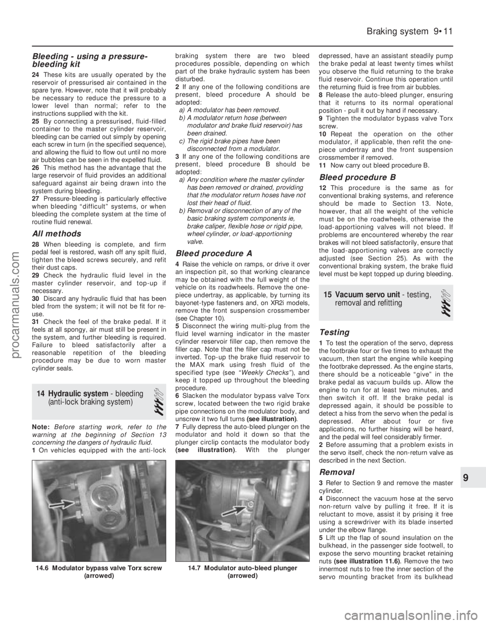
unscrew it two full turns (see illustration).
7 Fully depress the auto-bleed plunger on the
modulator and hold it down so that the
plunger circlip contacts the modulator body
(see illustration) . With the plunger depressed, have an assistant steadily pump
the brake pedal at least twenty times whilst
you observe the fluid returning to the brake
fluid reservoir. Continue this operation until
the returning fluid is free from air bubbles.
8
Release the auto-bleed plunger, ensuring
that it returns to its normal operational
position - pull it out by hand if necessary.
9 Tighten the modulator bypass valve Torx
screw.
10 Repeat the operation on the other
modulator, if applicable, then refit the one-
piece undertray and the front suspension
crossmember if removed.
11 Now carry out bleed procedure B.
Bleed procedure B
12This procedure is the same as for
conventional braking systems, and reference
should be made to Section 13. Note,
however, that all the weight of the vehicle
must be on the roadwheels, otherwise the
load-apportioning valves will not bleed. If
problems are encountered whereby the rear
brakes will not bleed satisfactorily, ensure that
the load-apportioning valves are correctly
adjusted (see Section 25). As with the
conventional braking system, the brake fluid
level must be kept topped up during bleeding.
15 Vacuum servo unit - testing,
removal and refitting
3
Testing
1 To test the operation of the servo, depress
the footbrake four or five times to exhaust the
vacuum, then start the engine while keeping
the footbrake depressed. As the engine starts,
there should be a noticeable “give” in the
brake pedal as vacuum builds up. Allow the
engine to run for at least two minutes, and
then switch it off. If the brake pedal is
depressed again, it should be possible to
detect a hiss from the servo when the pedal is
depressed. After about four or five
applications, no further hissing will be heard,
and the pedal will feel considerably firmer.
2 Before assuming that a problem exists in
the servo itself, check the non-return valve as
described in the next Section.
Removal
3 Refer to Section 9 and remove the master
cylinder.
4 Disconnect the vacuum hose at the servo
non-return valve by pulling it free. If it is
reluctant to move, assist it by prising it free
using a screwdriver with its blade inserted
under the elbow flange.
5 Lift up the flap of sound insulation on the
bulkhead, in the passenger side footwell, to
expose the servo mounting bracket retaining
nuts (see illustration 11.6) . Remove the two
innermost nuts to free the inner section of the
servo mounting bracket from its bulkhead
Braking system 9•11
14.7 Modulator auto-bleed plunger (arrowed)14.6 Modulator bypass valve Torx screw (arrowed)
9
1595Ford Fiesta Remakeprocarmanuals.com
http://vnx.su
Page 194 of 296
10
1595Ford Fiesta Remake
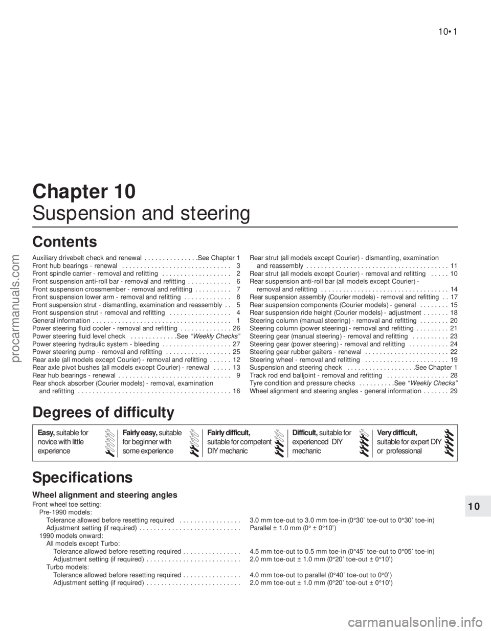
Wheel alignment and steering angles
Front wheel toe setting:Pre-1990 models: Tolerance allowed before resetting required . . . . . . . . . . . . . . . . . 3.0 mm toe-out to 3.0 mm toe-in (0°30’ toe-out to 0°30’ toe-in)
Adjustment setting (if required) . . . . . . . . . . . . . . . . . . . . . . . . . . . . Parallel ± 1.0 mm (0° ± 0°10’)
1990 models onward: All models except Turbo:
Tolerance allowed before resetting required . . . . . . . . . . . . . . \
. . 4.5 mm toe-out to 0.5 mm toe-in (0°45’ toe-out to 0°05’ toe-in)
Adjustment setting (if required) . . . . . . . . . . . . . . . . . . . . . . . . . . 2.0 mm toe-out ± 1.0 mm (0°20’ toe-out ± 0°10’)
Turbo models:
Tolerance allowed before resetting required . . . . . . . . . . . . . . \
. . 4.0 mm toe-out to parallel (0°40’ toe-out to 0°0’)
Adjustment setting (if required) . . . . . . . . . . . . . . . . . . . . . . . . . . 2.0 mm toe-out ± 1.0 mm (0°20’ toe-out ± 0°10’)
Chapter 10
Suspension and steering
Auxiliary drivebelt check and renewal . . . . . . . . . . . . . . .See Chapter 1
Front hub bearings - renewal . . . . . . . . . . . . . . . . . . . . . . . . . . . . . . 3
Front spindle carrier - removal and refitting . . . . . . . . . . . . . . . . . . . 2
Front suspension anti-roll bar - removal and refitting . . . . . . . . . . . . 6
Front suspension crossmember - removal and refitting . . . . . . . . . . 7
Front suspension lower arm - removal and refitting . . . . . . . . . . . . . 8
Front suspension strut - dismantling, examination and reassembly . . 5
Front suspension strut - removal and refitting . . . . . . . . . . . . . . . . . 4
General information . . . . . . . . . . . . . . . . . . . . . . . . . . . . . . . . . . . .\
. . 1
Power steering fluid cooler - removal and refitting . . . . . . . . . . . . . . 26
Power steering fluid level check . . . . . . . . . . . . .See
“Weekly Checks”
Power steering hydraulic system - bleeding . . . . . . . . . . . . . . . . . . . 27
Power steering pump - removal and refitting . . . . . . . . . . . . . . . . . . 25
Rear axle (all models except Courier) - removal and refitting . . . . . . 12
Rear axle pivot bushes (all models except Courier) - renewal . . . . . 13
Rear hub bearings - renewal . . . . . . . . . . . . . . . . . . . . . . . . . . . . . . . 9
Rear shock absorber (Courier models) - removal, examination and refitting . . . . . . . . . . . . . . . . . . . . . . . . . . . . . . . . . . . .\
. . . . . . 16 Rear strut (all models except Courier) - dismantling, examination
and reassembly . . . . . . . . . . . . . . . . . . . . . . . . . . . . . . . . . . . .\
. . . 11
Rear strut (all models except Courier) - removal and refitting . . . . . 10
Rear suspension anti-roll bar (all models except Courier) - removal and refitting . . . . . . . . . . . . . . . . . . . . . . . . . . . . . . . . . . . 14
Rear suspension assembly (Courier models) - removal and refitting . . 17
Rear suspension components (Courier models) - general . . . . . . . . 15
Rear suspension ride height (Courier models) - adjustment . . . . . . . 18
Steering column (manual steering) - removal and refitting . . . . . . . . 20
Steering column (power steering) - removal and refitting . . . . . . . . . 21
Steering gear (manual steering) - removal and refitting . . . . . . . . . . 23
Steering gear (power steering) - removal and refitting . . . . . . . . . . . 24
Steering gear rubber gaiters - renewal . . . . . . . . . . . . . . . . . . . . . . . 22
Steering wheel - removal and refitting . . . . . . . . . . . . . . . . . . . . . . . 19
Suspension and steering check . . . . . . . . . . . . . . . . . . .See Chapter 1
Track rod end balljoint - removal and refitting . . . . . . . . . . . . . . . . . 28
Tyre condition and pressure checks . . . . . . . . . .See “Weekly Checks”
Wheel alignment and steering angles - general information . . . . . . . 29
10•1
Specifications Contents
Easy, suitable for
novice with little
experience Fairly easy,
suitable
for beginner with
some experience Fairly difficult,
suitable for competent
DIY mechanic
Difficult,
suitable for
experienced DIY
mechanic Very difficult,
suitable for expert DIY
or professional
Degrees of difficulty
54321
procarmanuals.com
http://vnx.su
Page 195 of 296
:Steel . . . . . . . . . . . . . . . . . . . . . . . . . . . . . . . . . . . .\
. . . . . . . . . . . . . . 13 x 4.5, 13 x 5, 13 x 5.5
Alloy . .")
Roadwheels
Wheel types and sizes (dependent on model):Steel . . . . . . . . . . . . . . . . . . . . . . . . . . . . . . . . . . . .\
. . . . . . . . . . . . . . 13 x 4.5, 13 x 5, 13 x 5.5
Alloy . . . . . . . . . . . . . . . . . . . . . . . . . . . . . . . . . . . .\
. . . . . . . . . . . . . . 13 x 5.5, 14 x 5.5
Tyres
Tyre sizes (dependent on model) . . . . . . . . . . . . . . . . . . . . . . . . . . . . . . 135 R 13, 145 R 13, 155/70 R 13, 165/55 R 13, 165/65 R 13, 175/60 R 13, 185/55 R 14 or 185/60 R 13
Tyre pressures . . . . . . . . . . . . . . . . . . . . . . . . . . . . . . . . . . . .\
. . . . . . . . See “Weekly Checks”
Torque wrench settingsNmlbf ft
Front suspension
Hub/driveshaft retaining nut . . . . . . . . . . . . . . . . . . . . . . . . . . . . . . . . . . 205 to 235 151 to 173
Lower arm balljoint-to-spindle carrier pinch bolt . . . . . . . . . . . . . . . . . . 48 to 60 35 to 44
Front suspension strut to spindle carrier pinch-bolt . . . . . . . . . . . . . . . 80 to 90 59 to 66
Anti-roll bar link to front suspension strut nut . . . . . . . . . . . . . . . . . . . . 41 to 58 30 to 43
Anti-roll bar link to anti-roll bar nut . . . . . . . . . . . . . . . . . . . . . . . . . . . . . 41 to 58 30 to 43
Anti-roll bar retaining clamp bolts to lower arm . . . . . . . . . . . . . . . . . . . 20 to 28 15 to 21
Front suspension strut top-mount retaining nut . . . . . . . . . . . . . . . . . . . 40 to 52 30 to 38
Front suspension strut spring retaining nut . . . . . . . . . . . . . . . . . . . . . . 52 to 65 38 to 48
Front suspension crossmember bolts (XR2i only) . . . . . . . . . . . . . . . . . 80 to 90 59 to 66
Lower arm to lower arm mounting bracket bolts (using torque-to-yield
method with vehicle standing on its wheels): Stage 1 . . . . . . . . . . . . . . . . . . . . . . . . . . . . . . . . . . . .\
. . . . . . . . . . . . 5037
Stage 2 . . . . . . . . . . . . . . . . . . . . . . . . . . . . . . . . . . . .\
. . . . . . . . . . . . Slacken completely
Stage 3 . . . . . . . . . . . . . . . . . . . . . . . . . . . . . . . . . . . .\
. . . . . . . . . . . . 5037
Stage 4 . . . . . . . . . . . . . . . . . . . . . . . . . . . . . . . . . . . .\
. . . . . . . . . . . . Tighten through a further 90°
Rear suspension (all models except Courier)
Rear hub bearing retaining nut . . . . . . . . . . . . . . . . . . . . . . . . . . . . . . . . 250 to 290 184 to 214
Rear drum/hub to axle flange bolts . . . . . . . . . . . . . . . . . . . . . . . . . . . . 56 to 76 41 to 56
Rear axle to body mounting bracket bolts . . . . . . . . . . . . . . . . . . . . . . . 41 to 58 30 to 43
Rear axle trailing arm bush bolt* . . . . . . . . . . . . . . . . . . . . . . . . . . . . . . . 58 to 79 43 to 58
Rear strut top-mount retaining nuts . . . . . . . . . . . . . . . . . . . . . . . . . . . . 28 to 40 20 to 30
Rear strut-to-axle mounting bolt . . . . . . . . . . . . . . . . . . . . . . . . . . . . . . 102 to 138 75 to 102
Rear strut spring retaining through-bolt . . . . . . . . . . . . . . . . . . . . . . . . . 41 to 58 30 to 42
Anti-roll bar front mounting bolts . . . . . . . . . . . . . . . . . . . . . . . . . . . . . . 41 to 58 30 to 42
Anti-roll bar rear mounting bolts . . . . . . . . . . . . . . . . . . . . . . . . . . . . . . . 88 to 113 65 to 83
Load-apportioning valve operating link to axle beam . . . . . . . . . . . . . . 21 to 28 15 to 21
*Torque to be measured from the bolt head (not the nut)
Rear suspension (Courier models)
Rear hub bearing retaining nut . . . . . . . . . . . . . . . . . . . . . . . . . . . . . . . . 250 to 290 184 to 214
Shock absorber upper mounting . . . . . . . . . . . . . . . . . . . . . . . . . . . . . . 102 to 138 75 to 102
Shock absorber lower mounting . . . . . . . . . . . . . . . . . . . . . . . . . . . . . . 70 to 97 52 to 72
Rear suspension mounting bracket bolts . . . . . . . . . . . . . . . . . . . . . . . . 70 to 97 52 to 72
Manual steering
Steering gear to bulkhead . . . . . . . . . . . . . . . . . . . . . . . . . . . . . . . . . . . 70 to 97 57 to 72
Track rod end balljoint to spindle carrier steering arm . . . . . . . . . . . . . . 25 to 30 18 to 22
Track rod locknut to track rod end balljoint . . . . . . . . . . . . . . . . . . . . . . 57 to 68 42 to 50
Steering wheel to column shaft bolt . . . . . . . . . . . . . . . . . . . . . . . . . . . . 45 to 55 33 to 40
Steering column mounting nuts . . . . . . . . . . . . . . . . . . . . . . . . . . . . . . . 10 to 14 7 to 10
Steering column universal joint pinch-bolt . . . . . . . . . . . . . . . . . . . . . . . 45 to 56 33 to 41
Power steering
Steering wheel to column shaft bolt . . . . . . . . . . . . . . . . . . . . . . . . . . . . 5037
Steering gear to bulkhead . . . . . . . . . . . . . . . . . . . . . . . . . . . . . . . . . . . 8462
Steering gear fluid pipe unions . . . . . . . . . . . . . . . . . . . . . . . . . . . . . . . . 3123
Steering gear flexible coupling pinch-bolt . . . . . . . . . . . . . . . . . . . . . . . 5138
Track rod end balljoint to spindle carrier steering arm . . . . . . . . . . . . . . 2619
Track rod locknut to track rod end balljoint . . . . . . . . . . . . . . . . . . . . . . 6346
Steering pump mounting bolts . . . . . . . . . . . . . . . . . . . . . . . . . . . . . . . . 2518
Steering pump pulley bolts . . . . . . . . . . . . . . . . . . . . . . . . . . . . . . . . . . . 2518
High pressure fluid pipe to pump union . . . . . . . . . . . . . . . . . . . . . . . . . 6548
High pressure fluid pipe coupling joint . . . . . . . . . . . . . . . . . . . . . . . . . . 1713
Steering column mounting nuts . . . . . . . . . . . . . . . . . . . . . . . . . . . . . . . 129
Roadwheel nuts
All models . . . . . . . . . . . . . . . . . . . . . . . . . . . . . . . . . . . .\
. . . . . . . . . . . . 70 to 110 52 to 74
10•2 Suspension and steering
1595Ford Fiesta Remakeprocarmanuals.com
http://vnx.su
Page 210 of 296
Refitting
All models
38Refitting is a reversal of removal, bearing
in mind the following points:
a) Tighten all nuts and bolts to the specified torque. Remove the plugs from the
disconnected pipes, hoses and unions
and ensure that the pipes are located
correctly so that they do not foul any
surrounding components.
b) Refit the auxiliary drivebelt as described in
Chapter 1.
c) Where drained, refill the cooling system as described in Chapter 1.
d) Refit or reconnect any additional
components removed for access as
described in the relevant Sections and
Chapters of this manual.
e) On completion, bleed the power steering
hydraulic system as described in Section
27. Check for any signs of fluid leakage
from the system hoses and connections.
26 Power steering fluid cooler -
removal and refitting
2
Removal
1 Disconnect the battery negative (earth) lead
(refer to Chapter 5A, Section 1).
2 Position a suitable container beneath the
power steering fluid cooler hose connections,
then disconnect the hoses at the quick-fit
couplings on the fluid cooler. Allow the fluid to
drain from the hose and reservoir into the
container.
3 Plug the exposed ends of the hose and the
reservoir, to prevent the ingress of dirt and
excessive fluid loss.
4 Refer to Chapter 11 and remove the bonnet
lock assembly and the front bumper.
5 Undo the bolts securing the cooler side
support bracket and the bonnet lock stay, and
remove the fluid cooler and bonnet lock stay
as an assembly.
6 Undo the two bolts and remove the stay
from the fluid cooler.
Refitting
7 Refitting is a reversal of removal. On
completion, bleed the power steering
hydraulic system as described in Section 27.
27 Power steering hydraulic system - bleeding
2
1Following any operation in which the power
steering fluid lines have been disconnected,
the power steering system must be bled to
remove any trapped air.
2 With the front wheel in the straight-ahead
position, check the power steering fluid level
in the reservoir and, if low, top-up with fresh fluid to the “MAX” or “MAX COLD” level mark.
Pour the fluid slowly to prevent air bubbles
forming, and use only the specified fluid (refer
to
“Lubricants, fluids and tyre pressures” ).
3 Start the engine and allow it to idle. Check
the hoses and connections for leaks.
4 Stop the engine and recheck the fluid level.
Add more, if necessary, up to the “MAX” or
“MAX COLD” level mark.
5 Start the engine again, allow it to idle, then
bleed the system by slowly moving the
steering from lock-to-lock several times. This
should purge the system of all internal air.
However, if air remains in the system
(indicated by the steering operation being very
noisy), leave the vehicle overnight and repeat
the procedure again the next day.
6 If air still remains in the system, it may be
necessary to resort to the Ford method of
bleeding, which uses a vacuum pump and a
modified reservoir filler cap to which the pump
can be connected. Turn the steering to the
right until it is near the stop, then fit the
vacuum pump to the fluid reservoir, and apply
0.51 bars of vacuum. Maintain the vacuum for
a minimum of 5 minutes, then repeat
the procedure with the steering turned to the
left.
7 Keep the fluid level topped-up throughout
the bleeding procedure; note that the fluid
temperature increases, the level will rise.
8 On completion, switch the engine off, and
return the wheels to the straight-ahead
position.
28 Track rod end balljoint -
removal and refitting
2
Removal
1 Chock the rear wheels then jack up the
front of the car and support it on axle stands
(see “Jacking and Vehicle Support” ). Remove
the appropriate front roadwheel.
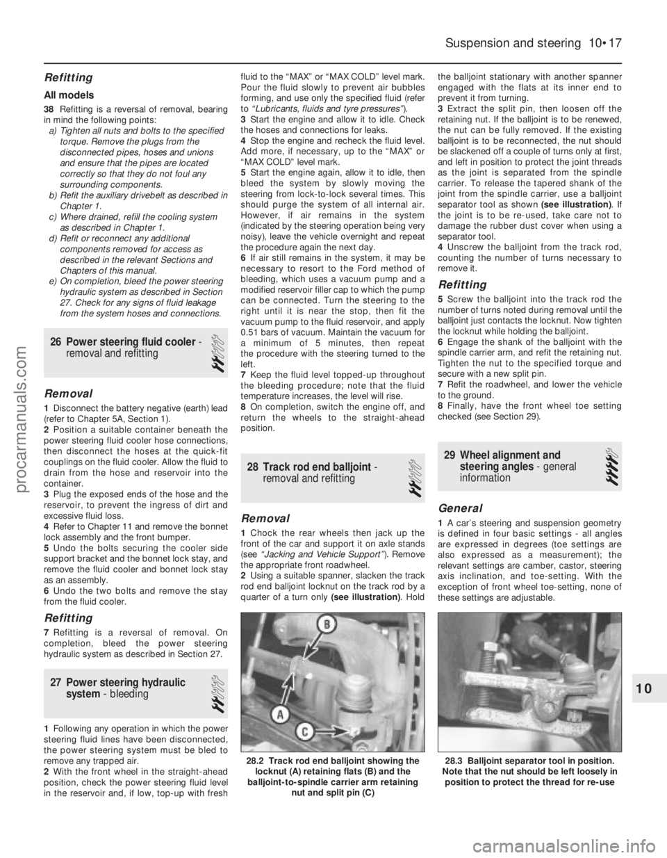
2 Using a suitable spanner, slacken the track
rod end balljoint locknut on the track rod by a
quarter of a turn only (see illustration). Holdthe balljoint stationary with another spanner
engaged with the flats at its inner end to
prevent it from turning.
3
Extract the split pin, then loosen off the
retaining nut. If the balljoint is to be renewed,
the nut can be fully removed. If the existing
balljoint is to be reconnected, the nut should
be slackened off a couple of turns only at first,
and left in position to protect the joint threads
as the joint is separated from the spindle
carrier. To release the tapered shank of the
joint from the spindle carrier, use a balljoint
separator tool as shown (see illustration). If
the joint is to be re-used, take care not to
damage the rubber dust cover when using a
separator tool.
4 Unscrew the balljoint from the track rod,
counting the number of turns necessary to
remove it.
Refitting
5 Screw the balljoint into the track rod the
number of turns noted during removal until the
balljoint just contacts the locknut. Now tighten
the locknut while holding the balljoint.
6 Engage the shank of the balljoint with the
spindle carrier arm, and refit the retaining nut.
Tighten the nut to the specified torque and
secure with a new split pin.
7 Refit the roadwheel, and lower the vehicle
to the ground.
8 Finally, have the front wheel toe setting
checked (see Section 29).
29 Wheel alignment and steering angles - general
information
4
General
1 A car’s steering and suspension geometry
is defined in four basic settings - all angles
are expressed in degrees (toe settings are
also expressed as a measurement); the
relevant settings are camber, castor, steering
axis inclination, and toe-setting. With the
exception of front wheel toe-setting, none of
these settings are adjustable.
Suspension and steering 10•17
28.3 Balljoint separator tool in position.
Note that the nut should be left loosely in position to protect the thread for re-use28.2 Track rod end balljoint showing the locknut (A) retaining flats (B) and the
balljoint-to-spindle carrier arm retaining
nut and split pin (C)
10
1595Ford Fiesta Remakeprocarmanuals.com
http://vnx.su
Page 211 of 296
Front wheel toe setting -
checking and adjustment
2Due to the special measuring equipment
necessary to accurately check the wheel
alignment, and the skill required to use it
properly, checking and adjustment is best left
to a Ford dealer or similar expert. Note that
most tyre-fitting shops now possess
sophisticated checking equipment. The
following is provided as a guide, should the
owner decide to carry out a DIY check.
3 The front wheel toe setting is checked by
measuring the distance between the front and
rear inside edges of the roadwheel rims.
Proprietary toe measurement gauges are
available from motor accessory shops.
Adjustment is made by screwing the track
rods in or out of their track rod end balljoints,
to alter the effective length of the track rod
assemblies.
4 For accurate checking, the vehicle must
be at the kerb weight, ie unladen and with a
full tank of fuel.
5 Before starting work, check the tyre
pressures and tread wear, the condition of the
hub bearings, the steering wheel free play,
and the condition of the front suspension
components (see Chapter 1). Correct any
faults found.
6 Park the vehicle on level ground, check that
the front roadwheels are in the straight-ahead
position, then rock the rear and front ends to settle the suspension. Release the handbrake,
and roll the vehicle backwards 1 metre, then
forwards again, to relieve any stresses in the
steering and suspension components.
7
Measure the distance between the front
edges of the wheel rims and the rear edges of
the rims. Subtract the smallest measurement
from the largest, and check that the result is
within the specified range.
8 If adjustment is necessary, apply the
handbrake, then jack up the front of the
vehicle and support it securely on axle stands
(see “Jacking and Vehicle Support” ). Turn the
steering wheel onto full-left lock, and record
the number of exposed threads on the right-
hand track rod. Now turn the steering onto
full-right lock, and record the number of
threads on the left-hand side. If there are the
same number of threads visible on both sides,
then subsequent adjustment should be made
equally on both sides. If there are more
threads visible on one side than the other, it
will be necessary to compensate for this
during adjustment. Note:It is most important
that after adjustment, the same number of
threads are visible on each track rod.
9 First clean the track rod end; if they are
corroded, apply penetrating fluid before
starting adjustment. Release the rubber gaiter
outboard clips (where necessary), and peel
back the gaiter; apply a smear of grease to
the inside of the gaiter, so that both are free, and will not be twisted or strained as their
respective track rods are rotated.
10
Use a straight-edge and a scriber or
similar to mark the relationship of each track
rod to its track rod end balljoint, then, holding
each track rod in turn, unscrew its locknut
fully.
11 Alter the length of the track rods, bearing
in mind the note made in paragraph 8. Screw
them into or out of the track rod end balljoints,
rotating the track rods using a self-grip
wrench. Shortening the track rods (screwing
them into their track rod end balljoints) will
reduce toe-in/increase toe-out.
12 When the setting is correct, hold the track
rods and securely tighten the track rod end
balljoint locknuts. Count the exposed threads
to check the length of both track rods. If they
are not the same, then the adjustment has not
been made equally, and problems will be
encountered with tyre scrubbing in turns;
also, the steering wheel spokes will no longer
be horizontal when the wheels are in the
straight-ahead position.
13 If the track rod lengths are the same, lower
the vehicle to the ground and re-check the
toe setting; re-adjust if necessary. When the
setting is correct, securely tighten the track rod
end balljoint locknuts. Ensure that the rubber
gaiters are seated correctly, and are not
twisted or strained, and secure them in position
with new retaining clips (where necessary).
10•18 Suspension and steering
1595Ford Fiesta Remakeprocarmanuals.com
http://vnx.su
Page 215 of 296
7.3a Removing the bonnet release latch
15 minutes after spraying on the final coat of
paint.Allow the new paint at least two weeks to
harden, then, using a paintwork renovator, or
a very fine cutting paste, blend the edges of
the paint into the existing paintwork. Finally,
apply wax polish.
Plastic components
With the use of more and more plastic body
components by the vehicle manufacturers (eg
bumpers. spoilers, and in some cases major
body panels), rectification of more serious
damage to such items has become a matter
of either entrusting repair work to a specialist
in this field, or renewing complete
components. Repair of such damage by the
DIY owner is not really feasible, owing to the
cost of the equipment and materials required
for effecting such repairs. The basic technique
involves making a groove along the line of the
crack in the plastic, using a rotary burr in a
power drill. The damaged part is then welded
back together, using a hot-air gun to heat up
and fuse a plastic filler rod into the groove.
Any excess plastic is then removed, and the
area rubbed down to a smooth finish. It is
important that a filler rod of the correct plastic
is used, as body components can be made of
a variety of different types (eg polycarbonate,
ABS, polypropylene). Damage of a less serious nature (abrasions,
minor cracks etc) can be repaired by the DIY
owner using a two-part epoxy filler repair
material. Once mixed in equal proportions,
this is used in similar fashion to the bodywork
filler used on metal panels. The filler is usually
cured in twenty to thirty minutes, ready for
sanding and painting. If the owner is renewing a complete
component himself, or if he has repaired it
with epoxy filler, he will be left with the
problem of finding a suitable paint for finishing
which is compatible with the type of plastic
used. At one time, the use of a universal paint
was not possible, owing to the complex range
of plastics encountered in body component
applications. Standard paints, generally
speaking, will not bond to plastic or rubber
satisfactorily. However, it is now possible to
obtain a plastic body parts finishing kit which
consists of a pre-primer treatment, a primer and coloured top coat. Full instructions are
normally supplied with a kit, but basically, the
method of use is to first apply the pre-primer
to the component concerned, and allow it to
dry for up to 30 minutes. Then the primer is
applied, and left to dry for about an hour
before finally applying the special-coloured
top coat. The result is a correctly-coloured
component, where the paint will flex with the
plastic or rubber, a property that standard
paint does not normally possess.
5 Major body damage
-
repair
5
Where serious damage has occurred, or
large areas need renewal due to neglect, it
means that complete new panels will need
welding-in, and this is best left to
professionals. If the damage is due to impact,
it will also be necessary to check completely
the alignment of the bodyshell, and this can
only be carried out accurately by a Ford
dealer, using special jigs. If the body is left
misaligned, it is primarily dangerous, as the
car will not handle properly; secondly, uneven
stresses will be imposed on the steering,
suspension and possibly transmission,
causing abnormal wear, or complete failure,
particularly to such items as the tyres.
6 Bonnet - removal,
refitting and adjustment
1
Removal
1 Raise the bonnet and support it on its stay.
2 Using a felt tip marker pen or similar, mark
around the hinge positions on the bonnet.
3 Cut the windscreen washer jet hose in the
engine compartment, or release it from its one-
way valve (if already fitted), then release the hose
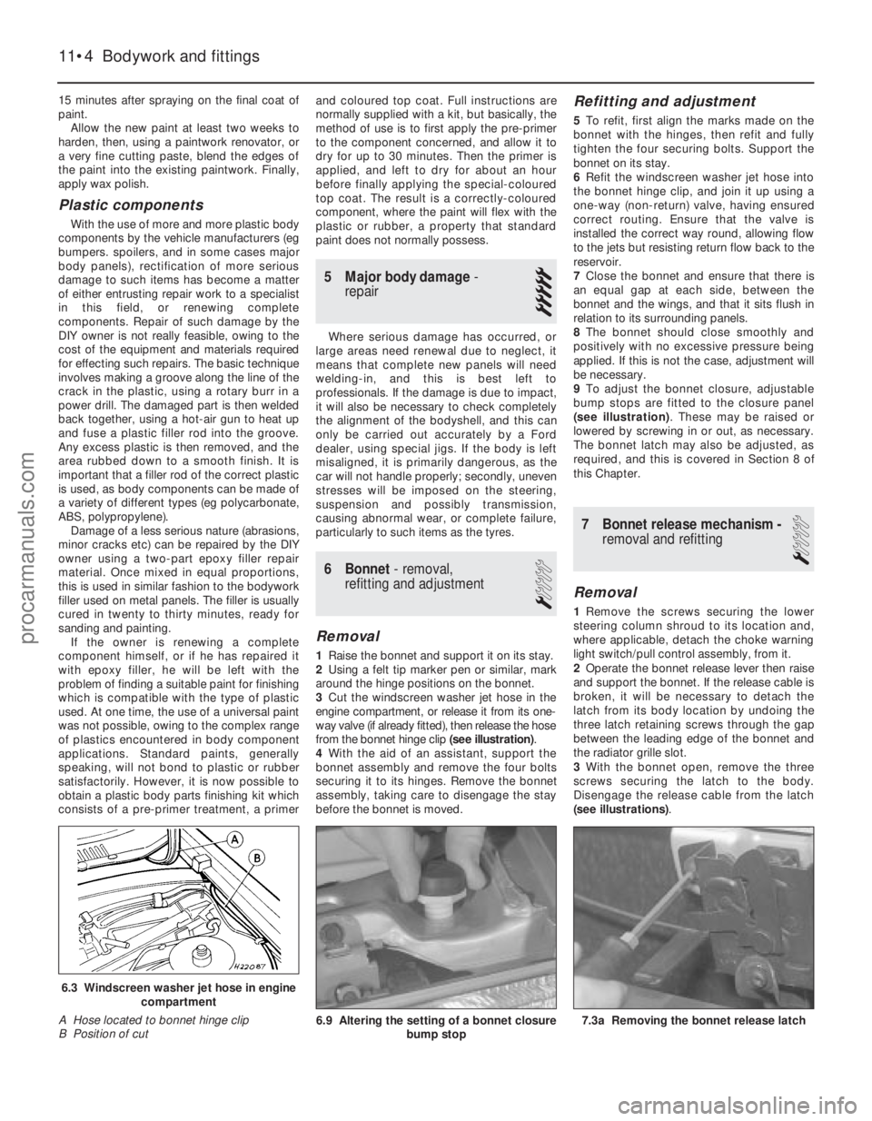
from the bonnet hinge clip (see illustration).
4 With the aid of an assistant, support the
bonnet assembly and remove the four bolts
securing it to its hinges. Remove the bonnet
assembly, taking care to disengage the stay
before the bonnet is moved.
Refitting and adjustment
5 To refit, first align the marks made on the
bonnet with the hinges, then refit and fully
tighten the four securing bolts. Support the
bonnet on its stay.
6 Refit the windscreen washer jet hose into
the bonnet hinge clip, and join it up using a
one-way (non-return) valve, having ensured
correct routing. Ensure that the valve is
installed the correct way round, allowing flow
to the jets but resisting return flow back to the
reservoir.
7 Close the bonnet and ensure that there is
an equal gap at each side, between the
bonnet and the wings, and that it sits flush in
relation to its surrounding panels.
8 The bonnet should close smoothly and
positively with no excessive pressure being
applied. If this is not the case, adjustment will
be necessary.
9 To adjust the bonnet closure, adjustable
bump stops are fitted to the closure panel
(see illustration) . These may be raised or
lowered by screwing in or out, as necessary.
The bonnet latch may also be adjusted, as
required, and this is covered in Section 8 of
this Chapter.
7 Bonnet release mechanism - removal and refitting
1
Removal
1Remove the screws securing the lower
steering column shroud to its location and,
where applicable, detach the choke warning
light switch/pull control assembly, from it.
2 Operate the bonnet release lever then raise
and support the bonnet. If the release cable is
broken, it will be necessary to detach the
latch from its body location by undoing the
three latch retaining screws through the gap
between the leading edge of the bonnet and
the radiator grille slot.
3 With the bonnet open, remove the three
screws securing the latch to the body.
Disengage the release cable from the latch
(see illustrations) .
11•4 Bodywork and fittings
6.9 Altering the setting of a bonnet closure
bump stop
6.3 Windscreen washer jet hose in enginecompartment
A Hose located to bonnet hinge clip
B Position of cut
1595Ford Fiesta Remakeprocarmanuals.com
http://vnx.su
Page 244 of 296
work should therefore be carried out by a
Ford dealer or service station with the
necessary facilities.
2Temporary adjustment can be made when
the headlight has been removed and refitted,
or to compensate for normal adjustment
whenever a heavy load is being carried. Turn
the adjustment screws at the rear of the
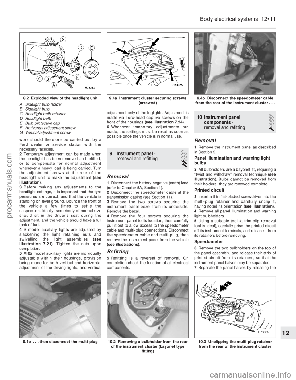
headlight unit to make the adjustment (see
illustration) .
3 Before making any adjustments to the
headlight settings, it is important that the tyre
pressures are correct, and that the vehicle is
standing on level ground. Bounce the front of
the vehicle a few times to settle the
suspension. Ideally, somebody of normal size
should sit in the driver’s seat during the
adjustment, and the vehicle should have a full
tank of fuel.
4 S model auxiliary lights are adjusted by
slackening the light retaining nuts and
swivelling the light assemblies (see
illustration 7.21) . Tighten the nuts upon
completion.
5 XR2i model auxiliary lights are individually
adjustable within their housings, provision
being made for both vertical and horizontal
adjustment of the driving lights, and vertical adjustment only of the foglights. Adjustment is
made via Torx-head captive screws on the
front of the housings
(see illustration 7.24) .
6 Whenever temporary adjustments are
made, the settings must be reset as soon as
possible once the vehicle is in normal use.
9 Instrument panel -
removal and refitting
2
Removal
1 Disconnect the battery negative (earth) lead
(refer to Chapter 5A, Section 1).
2 Disconnect the speedometer cable at the
transmission casing (see Section 11).
3 Remove the two screws securing the
instrument panel bezel from its underside.
Remove the bezel.
4 Remove the four screws securing the
instrument panel to its location, then carefully
pull it out to allow access to the speedometer
cable and multi-plug connections. Disconnect
the speedometer cable and multi-plug, then
remove the instrument panel from the vehicle
(see illustrations) .
Refitting
5Refitting is a reversal of removal. On
completion check the function of all electrical
components.
10 Instrument panel
components -
removal and refitting
1
Removal
1 Remove the instrument panel as described
in Section 9.
Panel illumination and warning light
bulbs
2 All bulbholders are a bayonet fit, requiring a
“twist and withdraw” removal technique (see
illustration) . Bulbs cannot be removed from
their holders -they are renewed complete.
Printed circuit
3 Insert a thin flat-bladed screwdriver into the
multi-plug retainer and carefully unclip it,
having noted its orientation (see illustration).
4 Remove all panel illumination and warning
light bulbholders.
5 Using a suitable tool (a trim clip removal
tool is ideal), carefully prise the printed circuit
off its instrument terminals, and release it from
its retainers before removing.
Speedometer
6 Remove the two bulbholders on the top of
the panel assembly, and release their strip of
printed circuit from its retainers, so that the
instrument panel halves may be separated.
7 Separate the panel halves by releasing the
Body electrical systems 12•11
9.4b Disconnect the speedometer cable
from the rear of the instrument cluster . . .9.4a Instrument cluster securing screws (arrowed)8.2 Exploded view of the headlight unit
A Sidelight bulb holder
B Sidelight bulb
C Headlight bulb retainer
D Headlight bulb
E Bulb protective cap
F Horizontal adjustment screw
G Vertical adjustment screw
10.3 Unclipping the multi-plug retainer from the rear of the instrument cluster10.2 Removing a bulbholder from the rear of the instrument cluster (bayonet type
fitting)9.4c . . . then disconnect the multi-plug
12
1595Ford Fiesta Remakeprocarmanuals.com
http://vnx.su
Page 273 of 296
Introduction
A selection of good tools is a fundamental
requirement for anyone contemplating the
maintenance and repair of a motor vehicle.
For the owner who does not possess any,
their purchase will prove a considerable
expense, offsetting some of the savings made
by doing-it-yourself. However, provided that
the tools purchased meet the relevant national
safety standards and are of good quality, they
will last for many years and prove an
extremely worthwhile investment. To help the average owner to decide which
tools are needed to carry out the various tasks
detailed in this manual, we have compiled
three lists of tools under the following
headings: Maintenance and minor repair,
Repair and overhaul , and Special. Newcomers
to practical mechanics should start off with
the Maintenance and minor repair tool kit, and
confine themselves to the simpler jobs around
the vehicle. Then, as confidence and
experience grow, more difficult tasks can be
undertaken, with extra tools being purchased
as, and when, they are needed. In this way, a
Maintenance and minor repair tool kit can be
built up into a Repair and overhaul tool kit over
a considerable period of time, without any
major cash outlays. The experienced do-it-
yourselfer will have a tool kit good enough for
most repair and overhaul procedures, and will
add tools from the Specialcategory when it is
felt that the expense is justified by the amount
of use to which these tools will be put.
Maintenance and minor repair
tool kit
The tools given in this list should be
considered as a minimum requirement if
routine maintenance, servicing and minor
repair operations are to be undertaken. We
recommend the purchase of combination
spanners (ring one end, open-ended the
other); although more expensive than open-
ended ones, they do give the advantages of
both types of spanner.
M Combination spanners: 8, 9, 10, 11, 12, 13,
14, 15, 16, 17, 19, 21, 22, 24 & 26 mm
M Adjustable spanner - 35 mm jaw (approx)
M Engine sump/gearbox drain plug key
(where applicable)
M Set of feeler gauges
M Spark plug spanner (with rubber insert)
M Spark plug gap adjustment tool
M Brake bleed nipple spanner
M Screwdrivers: Flat blade and cross blade –
approx 100 mm long x 6 mm dia
M Combination pliers
M Hacksaw (junior)
M Tyre pump
M Tyre pressure gauge
M Grease gun
M Oil can
M Oil filter removal tool
M Fine emery cloth
M Wire brush (small)
M Funnel (medium size)
Repair and overhaul tool kit
These tools are virtually essential for
anyone undertaking any major repairs to a
motor vehicle, and are additional to those
given in the Maintenance and minor repair list.
Included in this list is a comprehensive set of
sockets. Although these are expensive, they
will be found invaluable as they are so
versatile - particularly if various drives are
included in the set. We recommend the half-
inch square-drive type, as this can be used
with most proprietary torque wrenches. If you
cannot afford a socket set, even bought
piecemeal, then inexpensive tubular box
spanners are a useful alternative. The tools in this list will occasionally need
to be supplemented by tools from the Special
list:
M Sockets (or box spanners) to cover range in
previous list (including Torx sockets)
M Reversible ratchet drive (for use with
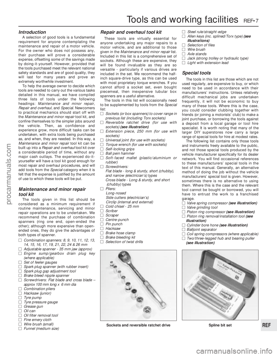
sockets) (see illustration)
M Extension piece, 250 mm (for use with
sockets)
M Universal joint (for use with sockets)
M Torque wrench (for use with sockets)
M Self-locking grips
M Ball pein hammer
M Soft-faced mallet (plastic/aluminium or
rubber)
M Screwdrivers:
Flat blade - long & sturdy, short (chubby),
and narrow (electrician’s) types
Cross blade - Long & sturdy, and short
(chubby) types
M Pliers:
Long-nosed
Side cutters (electrician’s)
Circlip (internal and external)
M Cold chisel - 25 mm
M Scriber
M Scraper
M Centre-punch
M Pin punch
M Hacksaw
M Brake hose clamp
M Brake bleeding kit
M Selection of twist drills M
Steel rule/straight-edge
M Allen keys (inc. splined/Torx type) (see
illustrations)
M Selection of files
M Wire brush
M Axle stands
M Jack (strong trolley or hydraulic type)
M Light with extension lead
Special tools
The tools in this list are those which are not
used regularly, are expensive to buy, or which
need to be used in accordance with their
manufacturers’ instructions. Unless relatively
difficult mechanical jobs are undertaken
frequently, it will not be economic to buy
many of these tools. Where this is the case,
you could consider clubbing together with
friends (or joining a motorists’ club) to make a
joint purchase, or borrowing the tools against
a deposit from a local garage or tool hire
specialist. It is worth noting that many of the
larger DIY superstores now carry a large
range of special tools for hire at modest rates. The following list contains only those tools
and instruments freely available to the public,
and not those special tools produced by the
vehicle manufacturer specifically for its dealer
network. You will find occasional references
to these manufacturers’ special tools in the
text of this manual. Generally, an alternative
method of doing the job without the vehicle
manufacturers’ special tool is given. However,
sometimes there is no alternative to using
them. Where this is the case and the relevant
tool cannot be bought or borrowed, you will
have to entrust the work to a franchised
garage.
M Valve spring compressor (see illustration)
M Valve grinding tool
M Piston ring compressor (see illustration)
M Piston ring removal/installation tool (see
illustration)
M Cylinder bore hone (see illustration)
M Balljoint separator
M Coil spring compressors (where applicable)
M Two/three-legged hub and bearing puller
(see illustration)
Sockets and reversible ratchet driveSpline bit set
Tools and working facilities REF•7
REF
1595 Ford Fiesta Remakeprocarmanuals.com
http://vnx.su